
Subscribe to Our Youtube Channel
Related Manuals for SIGLENT SDS5052X


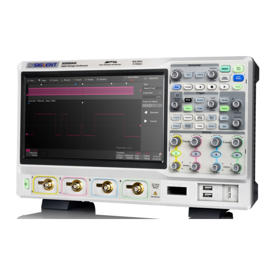
Summary of Contents for SIGLENT SDS5052X
- Page 1 SDS5000X Series Digital Oscilloscope User Manual SDS5000X Series Digital Oscilloscope User Manual UM0105X-E01C WWW.SIGLENT.COM 1 / 270...
-
Page 2: Table Of Contents
FRONT PANEL ..............................40 ................................ 40 VERVIEW ............................41 ERTICAL ONTROL ............................ 42 ORIZONTAL ONTROL ............................43 RIGGER ONTROL ............................43 UTTON ............................44 ETUP UTTON ......................44 ECODE IGITAL ONTROL ............................45 AVIGATE ONTROL ............................46 URSORS ONTROL WWW.SIGLENT.COM 2 / 270... - Page 3 16.3.2 SPI Trigger ............................128 16.3.3 SPI Serial Decode ..........................128 16.4 UART T ......................129 RIGGER AND ERIAL ECODE 16.4.1 UART Signal Settings..........................129 16.4.2 UART Trigger ............................130 16.4.3 UART Serial Decode ..........................131 WWW.SIGLENT.COM 3 / 270...
- Page 4 MASK TEST ..............................202 23.1 ..............................202 VERVIEW 23.2 ..............................204 ETUP 23.2.1 Create Mask............................204 23.2.2 Mask Editor ............................206 23.3 ............................. 208 23.4 ..............................209 PERATION DVM .................................. 210 24.1 ..............................210 VERVIEW 24.2 ................................211 WWW.SIGLENT.COM 4 / 270...
- Page 5 29.11 .............................. 261 29.12 ..............................262 EFAULT 29.13 ............................262 OWER ON 29.14 ................................ 262 EBUG REMOTE CONTROL ............................ 263 30.1 ............................... 263 ROWSER 30.2 ........................... 265 THER ONNECTIVITY TROUBLESHOOTING ..........................266 CONTACT SIGLENT ............................ 269 WWW.SIGLENT.COM 5 / 270...
-
Page 6: Introduction
SDS5000X Series Digital Oscilloscope User Manual Introduction This user manual includes important safety and installation information related to the SDS5000X series oscilloscopes and includes simple tutorials for basic operation of the oscilloscope. WWW.SIGLENT.COM 6 / 270... -
Page 7: General Safety Summary
WARNING could possibly cause bodily injury or death. If a WARNING is indicated, do not proceed until the safety conditions are fully understood and met. WWW.SIGLENT.COM 7 / 270... -
Page 8: Working Environment
Note: Installation (Overvoltage) Category II refers to the local distribution level, which is applicable to equipment connected to the mains supply (AC power source). Installation (Overvoltage) Category I refers to signal level, which is applicable WWW.SIGLENT.COM 8 / 270... -
Page 9: Cooling Requirements
Care must be taken to avoid restricting the airflow around the apertures (fan holes) at each side of the scope. To ensure adequate ventilation it is required to leave a 15 cm (6 inch) minimum gap WWW.SIGLENT.COM 9 / 270... -
Page 10: Ac Power
100 W of power. Note: The instrument automatically adapts to the AC line input within the following ranges: Voltage Range: 90 - 264 Vrms 90 - 132 Vrms Frequency Range: 47 - 63 Hz 380 - 420 Hz WWW.SIGLENT.COM 10 / 270... -
Page 11: Power And Ground Connections
The power cord should be unplugged from the AC outlet if the scope is not to be used for an extended period of time. CAUTION: The outer shells of the front panel terminals (CH1, CH2, CH3, CH4, EXT) are connected to the instrument’s chassis and therefore to the safety ground. WWW.SIGLENT.COM 11 / 270... -
Page 12: Calibration
If you suspect the scope’s protection has been impaired, disconnect the power cord and secure the instrument against any unintended operation. Proper use of the instrument depends on careful reading of all instruction and labels. WWW.SIGLENT.COM 12 / 270... - Page 13 SDS5000X Series Digital Oscilloscope User Manual Warning: Any use of the scope in a manner not specified by the manufacturer may impair the instrument’s safety protection. This instrument should not be directly connected to human subjects or used for patient monitoring. WWW.SIGLENT.COM 13 / 270...
-
Page 14: First Steps
The oscilloscope has a 3-year warranty (1-year warranty for probe attachments) from the date of shipment, during normal use and operation. SIGLENT can repair or replace any product that is returned to the authorized service center during the warranty period. We must first examine the product to make sure that the defect is caused by the process or material, not by abuse, negligence, accident, abnormal conditions or operation. -
Page 15: Maintenance Agreement
The oscilloscope's firmware has been thoroughly tested and is presumed to be functional. Nevertheless, it is supplied without warranty of any kind covering detailed performance. Products not made by SIGLENT are covered solely by the warranty of the original equipment manufacturer. -
Page 16: Document Conventions
Press the Utility button on the front panel as step 1, click the System Setting option on the screen as step 2, and click the Update option on the screen as step 3 to enter the upgrade interface. WWW.SIGLENT.COM 16 / 270... -
Page 17: Getting Started
5.2 Shut down Long press the power button for two seconds to turn off the oscilloscope. Note: The Power button does not disconnect the oscilloscope from the AC power WWW.SIGLENT.COM 17 / 270... -
Page 18: System Status
Follow the steps below to examine the software and hardware versions of the oscilloscope. Utility>System Setting>System Status See the section "System Status" for details. 5.4 Install Options A license is necessary to unlock a software option. See the section "Install Option" for details. WWW.SIGLENT.COM 18 / 270... -
Page 19: Probe
Probe The SDS5000X series oscilloscope package includes passive probes as standard accessories. Please visit the website at www.siglent.com technical data and ordering information. Probe Compensation When a probe is used for the first time, you should compensate it to match the input channel of the oscilloscope. - Page 20 SDS5000X Series Digital Oscilloscope User Manual Under Perfectly Over Compensated Compensated Compensated 5. Use a non-metallic driver to adjust the low-frequency compensation adjustment hole on the probe until the waveform displayed is as the “Perfectly compensated” in the figure above. WWW.SIGLENT.COM 20 / 270...
-
Page 21: Quick Start
D. USB Host Ports: Connect the USB host ports to USB storage devices for data transfer, or USB mouse / keyboard for control. E. Digital Input Connector: Receives digital signals from the SPL2016 digital probe. F. Analog Input Connectors WWW.SIGLENT.COM 21 / 270... -
Page 22: Rear Panel Overview
D. VGA Video Output: Connect the port to an external monitor. The resolution is 1024 * 600. E. LAN Port: Connect the port to the network for remote control. WWW.SIGLENT.COM 22 / 270... - Page 23 F. USB Ports: One USB device to connect with a PC for remote control and one USB host to connect with a USB storage device or USB mouse / keyboard. G. AC Power Input H. Handle WWW.SIGLENT.COM 23 / 270...
-
Page 24: Connecting To External Devices/Systems
USB mouse / keyboard to one of the USB host ports for controlling the instrument. 7.3.4 External Monitor Use a D-Sub cable to connect the VGA port to an external monitor. The video signal from the VGA port has a 1024 * 600 resolution. WWW.SIGLENT.COM 24 / 270... -
Page 25: Auxiliary Output
Press the WaveGen button on the front panel or touch the screen Utility AWG Menu to set the waveform. 7.3.7 Probes The SDS5000X series oscilloscope supports active probe and passive probes. The specifications and documents of the probe can be obtained at www.siglent.com. WWW.SIGLENT.COM 25 / 270... -
Page 26: Logic Probe
To connect the logic probe: Insert the probe, with the correct side facing up, until you hear a “click”. To remove the logic probe: Depress the buttons on each side of the probe, then pull out it. WWW.SIGLENT.COM 26 / 270... -
Page 27: Touch Screen Display
– that you can touch - to activate a control; in fact, you can alternate between clicking and touching the control, whichever is convenient. A. Menu Bar B. Grid Area C. Trigger Level Indicator D. Cursors E. Channel Descriptor box descriptor boxes WWW.SIGLENT.COM 27 / 270... -
Page 28: Menu Bar
All functionality can be accessed through the menu bar. It is not necessary for common operations. You can enter most menus by using the front panel or parameter description labels instead of the menu bar. However, the following operations can only be accessed through the menu bar: WWW.SIGLENT.COM 28 / 270... -
Page 29: Grid Area
Follow the steps below to set these parameters: > Display Intensity, > Display Graticule There are multiple indicators on the grid: Trigger Level Indicator shows the level where the waveform triggers on the vertical axis. WWW.SIGLENT.COM 29 / 270... -
Page 30: Channel Descriptor Box
C. Coupling and Input Impedance D. Vertical Scale Vertical Offset Probe Attenuation Factor Bandwidth Limit Indicators: The SDS5000X has two available bandwidth limits: 20 and 200 MHz. They are indicated by the following icons: :20MHzbandwidth limit :200MHzbandwidth limit WWW.SIGLENT.COM 30 / 270... - Page 31 0, the channel offset indicator is located in the middle of the vertical axis. Probe Attenuation Factor: Set the probe attenuation factor to match the actual attenuation of the probe. The oscilloscope automatically calculates the vertical scale according to the probe attenuation factor. For example, the WWW.SIGLENT.COM 31 / 270...
-
Page 32: Timebase And Trigger Descriptor Boxes
For example, if the scale is 500us/div, the time of each grid is 500us, and the full screen time range of the oscilloscope is 500us/div*10div = 5ms. # Samples: The number of sample points on the current screen. WWW.SIGLENT.COM 32 / 270... - Page 33 AC:The signal is capacitively coupled. DC levels are rejected. See the datasheet for details of the cut-off frequency. HFR:Signals are DC coupled to the trigger circuit, and a low-pass filter WWW.SIGLENT.COM 33 / 270...
- Page 34 Trigger level: The source voltage level or levels that mark the threshold for the trigger to fire. Trigger levels specified in Volts normally remain unchanged when the vertical gain or offset is modified. Trigger type: See the chapter "Trigger" for details. WWW.SIGLENT.COM 34 / 270...
-
Page 35: Dialog Box
The SDS5000X provides a couple of different ways to input/select parameters: Switch: Sets parameters with two states, such as to enable or disable a function. Touch the switch region to change from one state to the other. WWW.SIGLENT.COM 35 / 270... - Page 36 65 ns, input “65” on the virtual keypad, and then choose the unit n to complete the operation. On the virtual keypad, touching the button Max, Min, and Default quickly sets the parameter to its maximum, WWW.SIGLENT.COM 36 / 270...
-
Page 37: Touch Gestures
Turn on the Dialog box Turn off the Dialog box 8.7 Touch Gestures Waveforms, cursors and trigger level can be adjusted and rectangular zone can be drawn by touch gestures in the grid area. WWW.SIGLENT.COM 37 / 270... - Page 38 Draw a rectangular box to create a zone or a histogram region. At the beginning of the gesture keep the angle close to 45°so it can be recognized as the drawing box gesture WWW.SIGLENT.COM 38 / 270...
-
Page 39: Mouse And Keyboard Operation
8.9 Choosing the Language > > Follow Utility Language to choose the language. See the System Setting section "Language" for details. WWW.SIGLENT.COM 39 / 270... -
Page 40: Front Panel
All the knobs on the front panel are multi- function. They can be pushed as well as rotated. . Pushing a knob quickly recalls a specific function, which is indicated by the silkscreen near to the knob. WWW.SIGLENT.COM 40 / 270... -
Page 41: Vertical Control
B. Rotate the knob to adjust the DC offset or vertical position of the channel. Push to set the offset to zero C. Rotate the knob to adjust vertical scale (volts/div); push to switch to alternate between coarse and fine adjustments. WWW.SIGLENT.COM 41 / 270... -
Page 42: Horizontal Control
C. Push to enable horizontal Roll; push again to exit Roll mode. At timebase settings larger than 50ms/div, it is recommended to set the oscilloscope to Roll mode so that the waveform is displayed in real time. D. Push to enable Search; push again to close Search. WWW.SIGLENT.COM 42 / 270... -
Page 43: Trigger Control
9.5 Run/Stop Button Press the button to switch the acquisition state between Run and Stop. When the state is Run, and the button is illuminated in yellow; when the state is Stop, the button is illuminated in red. WWW.SIGLENT.COM 43 / 270... -
Page 44: Auto Setup Button
B. Press the button to turn on the digital channel and open the DIGITAL dialog box. Press again to turn off the digital channels. C. Press the button to turn on the math function and open the MATH WWW.SIGLENT.COM 44 / 270... -
Page 45: Navigate Control
9.8 Navigate Control A. Press the button to turn on navigate function and open the NAVIGATE dialog box. Press again to turn off navigate. B. Play backward C. Pause D. Play forward WWW.SIGLENT.COM 45 / 270... -
Page 46: Cursors Control
9.10 Universal Knob When the parameter setting area is highlighted, you can use the Universal Knob to adjustor set the parameter. Press the knob to select an option from the list. WWW.SIGLENT.COM 46 / 270... -
Page 47: Other Buttons
Press the button to recall the DISPLAY dialog box. The second press turn on Persist, and lights the button. Press the button again to turn off Persist. Recalls the UTILITY dialog box. Enables/Disables measurement and recalls the HISTORY dialog box. WWW.SIGLENT.COM 47 / 270... -
Page 48: Multiple Approaches To Recall Functions
The operations can be completed either by touch or by mouse clicks. 10.2 Descriptor Box For setup of channels, math, ref, timebase and trigger, there are dialog boxes at the bottom of the display. For the introduction of the descriptor box, see WWW.SIGLENT.COM 48 / 270... -
Page 49: Shortcut Button On The Front Panel
Most of the functions of the oscilloscope can be recalled directly by the shortcut buttons on the front panel. See the chapter "Front Panel" for details. To open the trigger setup dialog box, press the Setup button in the trigger control area on the front panel. WWW.SIGLENT.COM 49 / 270... -
Page 50: Quickly Capture The Signal
Auto Setup will not work on all signal types, especially time-varying bursts or slow signals (< 100 Hz). If Auto Setup cannot achieve desired settings, you can manually adjust the vertical, horizontal, and trigger systems. See the chapters "Vertical Setup", "Horizontal and Acquisition Setup" and "Trigger" for details. WWW.SIGLENT.COM 50 / 270... -
Page 51: Vertical Setup
Touch the channel descriptor box and then touch the Off button to disable it. Turn on C1 Turn off C1 12.2 Channel Setup Touch the channel descriptor box, a quick dialog will pop up. Vertical scale and WWW.SIGLENT.COM 51 / 270... - Page 52 The oscilloscope automatically switches to fine mode when the vertical scale is controlled by touch gesture. Activating a channel or touching in the quick dialog of the channel recalls the channel dialog box, displaying more parameters: WWW.SIGLENT.COM 52 / 270...
- Page 53 AC: The signal is capacitively coupled. DC signal components are rejected. See the datasheet for details of the cut-off frequency.AC coupling is suitable for observing AC signals with DC offset, such as power ripple. WWW.SIGLENT.COM 53 / 270...
- Page 54 The source can be C1~C4, Math and RefA~RefD. The length of the label is limited to 7 characters. The characters beyond this length will not be displayed. When the WWW.SIGLENT.COM 54 / 270...
- Page 55 50 Ω: Suitable for high frequency signals transmitted through 50 Ω coaxial cables and can minimize the amplitude distortion caused by impedance mismatching. Unit Voltage unit "V" or current unit "A”. When using the current probe, the unit should be set to "A". WWW.SIGLENT.COM 55 / 270...
- Page 56 Note: When the channel with deskew compensation is the trigger source, the trigger delay indicator does not change as the deskew value changes. Invert When invert is enabled, the waveform is 180 degrees opposite to the earth potential. WWW.SIGLENT.COM 56 / 270...
- Page 57 SDS5000X Series Digital Oscilloscope User Manual Before invert After invert WWW.SIGLENT.COM 57 / 270...
-
Page 58: Digital Channels
The SPL2016 is a logic probe designed to monitor up to 16 digital signals at once. The 16 digital channels are separated into two groups and each group has its own threshold, making it possible to simultaneously view data from different logic families. WWW.SIGLENT.COM 58 / 270... - Page 59 The equipment shall be used only for the purposes specified by the manufacturer. The SPL2016 probe is used only for SIGLENT's special series of oscilloscopes. Protection mechanisms can be compromised if the way the devices connected by the SPL2016 are not used for their intended purpose.
-
Page 60: Enable/Disable The Digital Channels
13.2 Enable/Disable the Digital Channels Turning on or off the digital channels is very similar to analog channels. Digital data can be stored as waveform files. Horizontal cursors and most of horizontal measurements also apply to digital waveforms. WWW.SIGLENT.COM 60 / 270... -
Page 61: Digital Channel Setup
Refer to the operation in the chapter "Vertical Setup" for details. 13.3 Digital Channel Setup Touch the digital descriptor box, then the quick menu of digital channel settings pops up above the descriptor box. In the menu height and position of digital channels can be set: WWW.SIGLENT.COM 61 / 270... - Page 62 E. ▲ to increase and ▼ to decrease the number of divisions occupied by the digital channels F. Reset the height to default value G. Turn off the digital channels H. Open digital dialog box on the right side Height=8div, Position=0div Height=4div, Position=1div WWW.SIGLENT.COM 62 / 270...
- Page 63 The threshold level determines how the input signal is evaluated. The threshold level can be set in the Logic Setting. The input voltage less than the threshold is recognized as a '0', and the input voltage greater than the threshold is recognized as a ‘1’. WWW.SIGLENT.COM 63 / 270...
- Page 64 SDS5000X Series Digital Oscilloscope User Manual The configurable logical level includes TTL, CMOS, LVCMOS 3.3V, LVCMOS 2.5V and Custom. The setting range of custom threshold is -10.0V to + 10.0V. WWW.SIGLENT.COM 64 / 270...
-
Page 65: Horizontal And Acquisition Setup
E. Set the trigger delay to zero F. Set the trigger delay to the left part of the screen G. Set the trigger delay to the right part of the screen H. Open the Acquire dialog box WWW.SIGLENT.COM 65 / 270... -
Page 66: Acquisition Setup
(5GSa/s) even when set to the5ms/div timebase. Note: The memory depth here is the upper limit of the memory space allocated by the oscilloscope. The actual sample points is related to the current timebase WWW.SIGLENT.COM 66 / 270... - Page 67 For example, at1ns/div timebase and 5GSa/s sample rate, the number of original points is 50, but the grid area includes 1000 horizontal pixels. In this case, the oscilloscope needs to interpolate the original points by 20. WWW.SIGLENT.COM 67 / 270...
-
Page 68: Acquisition
The acquisition mode is used to determine how to acquire and process the signal. Normal: The oscilloscope samples the signal with equal time interval. For most waveforms, the best display effect can be obtained using this mode. WWW.SIGLENT.COM 68 / 270... - Page 69 The more frames that are accumulated, the lower the noise is. For the SDS5000X, average processing is implemented by hardware engine, so it can still maintain a high waveform update rate when the acquisition mode is set to average. WWW.SIGLENT.COM 69 / 270...
- Page 70 Normal mode Eres mode (3-bit) Eres acquisition does not require the signal to be periodic, nor does it require WWW.SIGLENT.COM 70 / 270...
- Page 71 Eres mode. The higher the enhanced bits, the lower the bandwidth. The following table shows the relationship between Eres bits and bandwidth: Eres Bits -3dB bandwidth 0.25*Sample rate 0.115*Sample rate 0.055*Sample rate 0.028*Sample rate 0.014*Sample rate 0.007*Sample rate WWW.SIGLENT.COM 71 / 270...
-
Page 72: Roll Mode
If sequence mode is enabled, the display will not update until all of the sequences have been acquired. The SDS5000X can achieve a minimum 2us trigger interval in Sequence mode, corresponding WWW.SIGLENT.COM 72 / 270... - Page 73 Input a pulse sequence with a period of 50 ms to C1. Rise time of the pulse is 2ns,while fall time is 100ns; pulse width is 108ns, and amplitude is 1.6Vpp. Press the AutoSetup button on the front panel. WWW.SIGLENT.COM 73 / 270...
- Page 74 Sequence mode, and set the segments to maximum (53,969 in this example, up to 100,000 depending on the number of samples at the current time base). Wait patiently until the acquisition completes, then all the waveforms satisfying the trigger conditions are displayed onto the screen. WWW.SIGLENT.COM 74 / 270...
- Page 75 During acquisition, there is a counter on the screen indicating the number of segments that have been acquired. In the example, 53969 pulses can be obtained with the sample rate of 5GSa/s at the maximum memory depth. WWW.SIGLENT.COM 75 / 270...
-
Page 76: History
H. Set the time interval between two frames when playing automatically Enable “Stop on Search Event” function, which allows to navigate search events across history frames. J. List, displays the frame index and time label for each frame. WWW.SIGLENT.COM 76 / 270... - Page 77 Observing the 5412th frame captured by Sequence in history mode Touch the List area, turn on the list, in which the time label corresponding to the 5412th waveform is displayed. The time resolution is microseconds. Time label WWW.SIGLENT.COM 77 / 270...
- Page 78 Touch the Interval Time area to control the speed of automatic play. In the process of automatic play, the list will automatically scroll to the current frame. WWW.SIGLENT.COM 78 / 270...
-
Page 79: Zoom
(or right). The horizontal position of the zoom area, the horizontal position of the waveform, the horizontal scale of Zoom window and the horizontal scale of main window can also be controlled WWW.SIGLENT.COM 79 / 270... - Page 80 Adjust the horizontal scale of Zoom window by horizontal pinch and spread in the gray area of the main window or in the Zoom window Adjust the horizontal scale of main window by pinch and spread in the zoom area of the main window WWW.SIGLENT.COM 80 / 270...
-
Page 81: Trigger
Pre-trigger Buffer Acquisition Memory Below are the definition of the states in the process of filling the acquisition memory: Arm: The pre-trigger buffer is not full, and the oscilloscope does not respond to any trigger events. WWW.SIGLENT.COM 81 / 270... - Page 82 You need to have some knowledge of the signal-under-test to quickly capture the desired waveform. WWW.SIGLENT.COM 82 / 270...
-
Page 83: Trigger Setup
E. Set the trigger mode to "Single", which is equivalent to pressing the Single button on the front panel F. Set the trigger mode to "Normal", which is equivalent to pressing the Normal button on the front panel WWW.SIGLENT.COM 83 / 270... -
Page 84: Trigger Level
Trigger Related Label Trigger level Indicator Horizontal 0 position Horizontal 0 position(out of Indicator screen)Indicator 15.3 Trigger Level Both analog and digital triggers must have a correct trigger level value. The WWW.SIGLENT.COM 84 / 270... -
Page 85: Trigger Mode
Note: In Auto mode, if the signal satisfies the trigger conditions but cannot trigger the oscilloscope stably, it may be that interval between two trigger events exceeds the timeout period. Try Normal mode in this case. WWW.SIGLENT.COM 85 / 270... -
Page 86: Trigger Type
Edge-- Trigger on rising edge, falling edge or both Slope-- Trigger when an edge crosses two thresholds which lie inside or outside a selected time range WWW.SIGLENT.COM 86 / 270... - Page 87 DC coupling Serial--Trigger on specified condition in a serial bus. See the chapter "Serial Trigger and Decode" for details. Qualified -- Trigger with edge trigger setting only after the qualifying condition is satisfied WWW.SIGLENT.COM 87 / 270...
-
Page 88: Edge Trigger
The slope trigger looks for a rising or falling transition from one level to another level in the specified time range. For example, positive slope time is defined as the time difference between the two crossing points of trigger level line A and B WWW.SIGLENT.COM 88 / 270... - Page 89 Level knob on the front panel. To set the lower level is the similar. 2. Use the Level knob on the front panel directly to set the level value. WWW.SIGLENT.COM 89 / 270...
- Page 90 Holdoff, coupling and noise reject can be set in slope trigger, see the sections "Holdoff", "Trigger Coupling" and "Noise Reject" for details. WWW.SIGLENT.COM 90 / 270...
-
Page 91: Pulse Trigger
Below is an example of trigger condition is set to 100ns<positive pulse width<300ns. WWW.SIGLENT.COM 91 / 270... -
Page 92: Video Trigger
Source, standard and synchronization mode can be set in video trigger dialog box. When the synchronization mode is "Select", line and field can be specified. Touch the Standard and select the video standard. The SDS5000X supports the following video standards: WWW.SIGLENT.COM 92 / 270... - Page 93 “Interlace” ratio. Therefore, the number of fields selected and the number of lines corresponding to each field can also be varied. If the "Of Lines" is set to 800, the correct relationship between them is as follows: WWW.SIGLENT.COM 93 / 270...
- Page 94 The following table shows the corresponding relations between line and field for all video standards (except for Custom) Standard Field 1 Field 2 1 to263 1 to262 NTSC 1 to313 1 to312 WWW.SIGLENT.COM 94 / 270...
- Page 95 5. Touch the Sync and select the "Select" to make the Field and Line optional, then select "1" in the "Field", and set the "Line" to "22" by using the universal knob or the virtual keypad. WWW.SIGLENT.COM 95 / 270...
- Page 96 6. Touch the Sync to select the synchronization mode for the input signal: a) Select the "Any" mode, and the signal can be triggered on any line that meets the trigger condition. WWW.SIGLENT.COM 96 / 270...
-
Page 97: Window Trigger
Delta value to set the window range. In this mode, the lower and the upper trigger levels always move together. If the lower and the upper trigger levels are both within the waveform amplitude range, the oscilloscope will trigger on both rising and falling edges. WWW.SIGLENT.COM 97 / 270... - Page 98 To set the center level is the similar. 2. Directly use the Level knob on the front panel. Press the knob to switch between “Level +/-Delta" and "Center Level", and rotate it to set values. WWW.SIGLENT.COM 98 / 270...
-
Page 99: Interval Trigger
Trigger source, slope (rising, falling), limit range and time value can be set in the trigger dialog box. Holdoff, coupling and noise reject can be set in interval trigger, see the sections "Holdoff", "Trigger Coupling" and "Noise Reject" for details. WWW.SIGLENT.COM 99 / 270... -
Page 100: Dropout Trigger
Trigger source, slope (rising, falling), dropout type and time value can be set in the trigger dialog box. Holdoff, coupling and noise reject can be set in dropout trigger, see the sections "Holdoff", "Trigger Coupling" and "Noise Reject" for details. WWW.SIGLENT.COM 100 / 270... -
Page 101: Runt Trigger
A negative runt pulse across through the high level but not the low level. Holdoff, coupling and noise reject can be set in dropout trigger, see the sections "Holdoff", "Trigger Coupling" and "Noise Reject" for details. WWW.SIGLENT.COM 101 / 270... -
Page 102: Pattern Trigger
Each channel can be set to "Low", "High" or "Don't Care". The threshold can be determined by setting the Level Value. When digital channels are turned on, the logic state of the digital channel can also be set in the source setting dialog box. WWW.SIGLENT.COM 102 / 270... -
Page 103: Qualified Trigger
The qualified types include “State”, “State with Delay”, “Edge” and “Edge with Delay”. When the type is “State”, the oscilloscope triggers on the first edge when the qualified source is in the specified state (High or Low). When the WWW.SIGLENT.COM 103 / 270... - Page 104 Source Qualified Edge = Rising Trigger Edge = Rising Position Touch the Qualified Setting region to set the qualified source and threshold; Touch the Edge Setting region to set the edge trigger source, threshold and slope. WWW.SIGLENT.COM 104 / 270...
-
Page 105: Trigger Source
× Window √ × × × Interval √ × × √ Dropout √ × × √ Runt √ × × × Pattern √ × × √ Serial √ × × √ Qualified √ × × √ WWW.SIGLENT.COM 105 / 270... -
Page 106: Holdoff
The oscilloscope will not trigger until the counter tracking holdoff events reaches the set value. In the following figure, the holdoff event is set to 3, and the signal is triggered on the fourth edge. WWW.SIGLENT.COM 106 / 270... - Page 107 Last Trig Time--The initial position of holdoff is the time of the last trigger. In the example above, the last trigger position is at the second rising edge of the pulse sequence and the second holdoff starts from that point. WWW.SIGLENT.COM 107 / 270...
-
Page 108: Trigger Coupling
See the datasheet for details of the cut- off frequency. 15.9 Noise Reject Noise Reject adds additional hysteresis to the trigger circuitry. By increasing the trigger hysteresis, the noise immunity becomes better but the trigger sensitivity degrades. WWW.SIGLENT.COM 108 / 270... -
Page 109: Zone Trigger
The SDS5000X includes a zone trigger to help isolate elusive glitches. There are two user-defined areas: Zone1 and Zone2. Users can set the property of each zone as “intersect” or “not intersect” as an additional condition to further WWW.SIGLENT.COM 109 / 270... - Page 110 The zones can be created and moved by gestures or by setting Zone> Zone Setting in the dialog box. The color of the zone’s outline is consistent with the color of the specified source (Channel 1 = Yellow, etc...). Gesture WWW.SIGLENT.COM 110 / 270...
- Page 111 When the finger moves out of the screen, a menu pops up for selecting the zone and setting the zone properties: Once a zone is created, it can be moved by dragging. Just touch and hold the WWW.SIGLENT.COM 111 / 270...
- Page 112 Touch the regions above to set the value by the universal knob or the virtual keypad. Note: If zone1 and zone2 are both turned on, the result of the "AND" operation in two zones becomes the qualified condition of triggering. WWW.SIGLENT.COM 112 / 270...
- Page 113 In this case zone trigger is a quick and simple way to capture the interested waveform. Enable the zone trigger, and draw a box to intersect with the bus contention part, as shown in the figure below: WWW.SIGLENT.COM 113 / 270...
- Page 114 SDS5000X Series Digital Oscilloscope User Manual Now, we can accurately capture the exact bus contention waveform: WWW.SIGLENT.COM 114 / 270...
-
Page 115: Serial Trigger And Decode
B. Select the serial bus protocol C. Set the signal, including the mapping relation between channels and bus signals, and the thresholds D. Trigger setting Press the Decode button or touch the Analysis>Decode to turn on the serial decode dialog box: WWW.SIGLENT.COM 115 / 270... - Page 116 Below are detailed descriptions of trigger and decode steps for each protocol. I2C Trigger and Serial Decode SPI Trigger and Serial Decode UART Trigger and Serial Decode CAN Trigger and Serial Decode LIN Trigger and Serial Decode 错误!未找到引用源。 WWW.SIGLENT.COM 116 / 270...
-
Page 117: I2C Trigger And Serial Decode
B. Set the threshold level of SCL. It is 1.7V for the LVTTL signal in this example. C. Set the source of SDA. In the example above, SDA is connected to C1. D. Set the threshold level of the SDA channel. WWW.SIGLENT.COM 117 / 270... -
Page 118: I2C Trigger
16.2.2 I2C Trigger When the protocol is set to I2C, the following trigger conditions can be set: Start, Stop, Restart, No Ack, EEPROM, or an R/W frame with specific device address and data value. WWW.SIGLENT.COM 118 / 270... - Page 119 SCL is high. Restart—The oscilloscope will be triggered when another “Start” occurs before a “Stop". No Ack—The oscilloscope will be triggered when the SDA line is high during any SCL’s ACK bit. WWW.SIGLENT.COM 119 / 270...
- Page 120 Ack bit followed by the R/W bit. Frame (Start: 7-bit address: R/W: Ack: Data: Ack: Data2)—If all bits match, then trigger on the Ack bit followed by the Data2. WWW.SIGLENT.COM 120 / 270...
- Page 121 SDS5000X Series Digital Oscilloscope User Manual 10 Address&Data —If all bits match, then trigger on the Ack bit followed by the Data. Frame (Start: Address 1st byte: R/W: Ack: Address 2nd byte: Ack: Data) WWW.SIGLENT.COM 121 / 270...
- Page 122 Touch the Address Length to select "7-bits" or "10-bits" to match the address of the input signal. Touch the Data Length and turn the universal knob or by virtual keypad to set the data length to match the data length of input signal. WWW.SIGLENT.COM 122 / 270...
-
Page 123: I2C Serial Decode
C. List display area. Decode result of multiple frames can be displayed in the list, in which each row shows the time label and decode result of a frame. Touch List to set the parameters of list. D. Decode dialog box WWW.SIGLENT.COM 123 / 270... - Page 124 TIME—The horizontal offset of the current data frame head relative to the trigger position. Address—Address value. For example, "0x2AB" means that address = 2AB with acknowledgement. R/W—Read address or write address. DATA—Data bytes. WWW.SIGLENT.COM 124 / 270...
- Page 125 R/W bit is represented together with the address. For example, the address 0x4E: Write: Ack, is displayed as "0x4E (W)" when the R/W bit is not included, and is displayed as "0x9C"when the R/W bit is included. WWW.SIGLENT.COM 125 / 270...
-
Page 126: Spi Trigger And Serial Decode
When the rising edge of the clock is aligned with the data, the falling edge is selected to latch the data. WWW.SIGLENT.COM 126 / 270... - Page 127 This setting is suitable for case where CS signal is not connected, or the number of oscilloscope channels is insufficient (such as two-channel oscilloscopes). The method of copying settings is the same as I2C signal settings. See "I2C Signal Settings" for details. WWW.SIGLENT.COM 127 / 270...
-
Page 128: Spi Trigger
D. Set the bit order to MSB or LSB E. Return to previous menu 16.3.3 SPI Serial Decode The configuration of SPI decoding is similar to I2C. In the Bus Config menu, Data Length (4-32 bit) and Bit Order (LSB or MSB) are configurable. WWW.SIGLENT.COM 128 / 270... -
Page 129: Uart Trigger And Serial Decode
The process of specifying the source and threshold is similar to "I2C Signal Settings". In the BusConfig menu of trigger or decode, the following parameters are available: WWW.SIGLENT.COM 129 / 270... -
Page 130: Uart Trigger
G. Return to previous menu The method of copying settings is the same as I2C signal settings. See "I2C Signal Settings" for details. 16.4.2 UART Trigger Touch Trigger Setting in the dialog box to set the trigger condition: WWW.SIGLENT.COM 130 / 270... -
Page 131: Uart Serial Decode
Error—The oscilloscope performs parity check on the data according to the parity type set by the user, and triggers if the check value is incorrect. 16.4.3 UART Serial Decode The configuration of UART decoding is similar to that of I2C decoding. WWW.SIGLENT.COM 131 / 270... -
Page 132: Can Trigger And Serial Decode
20 kb/s, 50 kb/s, 100 kb/s, 125 kb/s, 250 kb/s, 500 kb/s, 800 kb/s, 1 Mb/s or Custom. The method of copying settings is the same as I2C signal settings. See "I2C Signal Settings" for details. WWW.SIGLENT.COM 132 / 270... -
Page 133: Can Trigger
3rd, or 4th byte), Data1 and Data2 can be set. Error—The oscilloscope triggers on the error frame. 16.5.3 CAN Serial Decode The configuration of CAN decoding is similar to that of I2C decoding. On the bus: WWW.SIGLENT.COM 133 / 270... - Page 134 “R”. ID— ID of the frame, 11-bits or 29-bits ID are automatically detected. Length— Data length. Data— Data values. CRC— Cycle redundancy check. Ack— Acknowledge bit. WWW.SIGLENT.COM 134 / 270...
-
Page 135: Lin Trigger And Serial Decode
In BusConfig menu of trigger and decode, baud rate can be set to: 600 b/s,1200 b/s, 2400 b/s, 4800 b/s, 9600 b/s, 19200 b/s or Custom. The method of copying settings is the same as I2C signal settings. See “I2C Signal Settings” for details. WWW.SIGLENT.COM 135 / 270... -
Page 136: Lin Trigger
Data Error—The oscilloscope will trigger when data error happens. 16.6.3 LIN Serial Decode The configuration of LIN decoding is similar to that of I2C decoding. On the bus: ID, LEN (data length), DATA and CHK are all displayed in white. WWW.SIGLENT.COM 136 / 270... - Page 137 In the list view: Time—The horizontal offset of the current data frame head relative to the trigger position. ID—ID of the frame. Data length—Data length. ID Parity—ID parity check. Data—Data values. Checksum—Data checksum. WWW.SIGLENT.COM 137 / 270...
-
Page 138: Flexray Trigger And Serial Decode
The method of copying settings is the same as I2C signal settings. See "I2C Signal Settings" for details. 16.7.2 FlexRay Trigger Touch Trigger Setting in the FlexRay trigger dialog box to set the trigger conditions: TSS— The oscilloscope triggers on the transmission start sequence. WWW.SIGLENT.COM 138 / 270... -
Page 139: Flexray Serial Decode
The ID is displayed in the frame and is displayed in white. PL (Valid Data Length) is displayed in frames, in words, in white. HCRC (Head Check Code) is displayed in the frame and displayed in WWW.SIGLENT.COM 139 / 270... - Page 140 FID— Frame ID, symbol occupy a single line of the list. PL— Valid Data Length HCRC— Head Check Code CYC— Cycle count Data— Data values FCRC— Data Check Code WWW.SIGLENT.COM 140 / 270...
-
Page 141: Can Fd Trigger And Serial Decode
The method of copying settings is the same as I2C signal settings. See "I2C Signal Settings" for details. 16.8.2 CAN FD Trigger Touch Trigger Setting in the CAN FD trigger dialog box to set the trigger conditions: WWW.SIGLENT.COM 141 / 270... - Page 142 ID and data.ID, ID Bits (11-bit or 29-bit), Curr ID Byte (1st, 2nd, 3rd, or 4th byte), Data1 and Data2 can be set. Error— The oscilloscope triggers on the error frame. Error Frame Stuff Bit Error WWW.SIGLENT.COM 142 / 270...
-
Page 143: Can Fd Serial Decode
CRC is displayed in white. Ack is displayed in white. indicates there is not enough space on the display to show complete content of a frame and some content is hidden. In the list view: WWW.SIGLENT.COM 143 / 270... - Page 144 "Std", CAN FD frame is represented by "FD", extended frame is represented by "Ext" and remote frame is represented by "RTR". ID— Frame ID. Length— Data length. Data— Data bytes. CRC— Cycle redundancy check. Ack— Acknowledge bit. WWW.SIGLENT.COM 144 / 270...
-
Page 145: I2S Trigger And Serial Decode
Left CH. Low–Select left channel when WS is low and right channel when WS is high. High–Select right channel when WS is low and left channel when WS is high. WWW.SIGLENT.COM 145 / 270... -
Page 146: I2S Trigger
G. When the "Trigger Condition" is Data, set the compare type to: =, >, < H. When the "Trigger Condition" is Data, set the data value Return to previous menu Trigger Condition Data— Trigger on data. WWW.SIGLENT.COM 146 / 270... - Page 147 Rising Edge— Trigger on signals greater than the Threshold setting value. Touch Threshold to set the threshold by the universal knob or virtual keypad. The range of values is related to the number of Data Bits. WWW.SIGLENT.COM 147 / 270...
-
Page 148: I2S Serial Decode
Time— The horizontal offset of the current data frame head relative to the trigger position. Type— Channel type, left channel is represented by "Left CH" and right channel is represented by "Right CH". Data— Data bytes Error— Error WWW.SIGLENT.COM 148 / 270... -
Page 149: Mil-Std-1553B Trigger And Serial Decode
Data word and the data are displayed in the frame and displayed in white. Check Code is displayed in the frame and displayed in white. WWW.SIGLENT.COM 149 / 270... - Page 150 In the decoding list view: Time— The horizontal offset of the current data frame head relative to the trigger position. RTA— The RT address Type— Type of the word Data— Data values Error— Error type WWW.SIGLENT.COM 150 / 270...
-
Page 151: Cursors
X2, X1-X2, Y1, Y2 and Y1-Y2, used to indicate X-axis values(time or frequency) and Y-axis values(amplitude) on a selected waveform(CH1/CH2/CH3/CH4/MATH/REFA/REFB/REFC/REFD). Press the Cursors button on the front panel or touch the menu Cursors>Menu to open cursors dialog box: WWW.SIGLENT.COM 151 / 270... - Page 152 Track -- The cursor type is automatically set to "horizontal+vertical". In this mode, only horizontal cursors are adjustable, while the vertical cursors automatically attach to the cross-point of the cursor and the source WWW.SIGLENT.COM 152 / 270...
- Page 153 SDS5000X Series Digital Oscilloscope User Manual waveform. Manual Mode Track Mode WWW.SIGLENT.COM 153 / 270...
- Page 154 X1 and X2 simultaneously. Y(vertical)–Horizontal dotted lines that measure vertical voltage or current (depending on the unit of the selected channel). When the cursors source is the math function, the units will match the math function. WWW.SIGLENT.COM 154 / 270...
- Page 155 Y1- Y2—The difference between Y1 and Y2. After this option is selected, turn the universal knob to move both Y1 and Y2 simultaneously. X+Y (horizontal+vertical) -- Both the X cursors and Y cursors are enabled. WWW.SIGLENT.COM 155 / 270...
- Page 156 Y cursors reference: Fixed Offset– When the vertical scale is changed, the value of Y cursors remain fixed. Fixed Position– When the vertical scale is changed, the y cursors WWW.SIGLENT.COM 156 / 270...
- Page 157 SDS5000X Series Digital Oscilloscope User Manual remain fixed to the grid position on the display. Take X cursors reference as an example to demonstrate the scaling effect of different settings: Timebase=50ns/div,X1=-50ns=-1div,X2=100ns=2div WWW.SIGLENT.COM 157 / 270...
-
Page 158: Select And Move Cursors
The cursors can be selected and moved directly by gestures and the universal knob on the front panel, in addition they can be selected in the cursors dialog box. Gestures Directly touch the cursor and drag it, as shown below: WWW.SIGLENT.COM 158 / 270... - Page 159 Move the cursor position by turning the universal knob on the front panel. Press the knob to select different cursor lines. For example, if the current cursor is X1, press to select X2, and press again to select X1-X2. WWW.SIGLENT.COM 159 / 270...
- Page 160 First, a rough adjustment is achieved by using gestures and then fine adjustment is achieved by using the universal knob. Dialog Box Touch the cursor name area of the dialog box, select the cursor(s) in the pop-up list, then rotate universal knob to adjust the position. WWW.SIGLENT.COM 160 / 270...
-
Page 161: Measurement
Some parameter measurements(such as period) accumulate all measurements in a frame, but the displayed value is always the first value. If you want to know the distribution of multiple parameters in one frame, you should use the statistics function. WWW.SIGLENT.COM 161 / 270... - Page 162 “All Meas”, the "All Meas" parameter area is displayed C. Statistics histogram display area D. Measure dialog box Press the Measure button on the front panel or touch Measure>Menu to open the dialog box. WWW.SIGLENT.COM 162 / 270...
-
Page 163: Set Parameters
Set the time gate for measurement 18.2 Set Parameters Touch Type in the measure dialog box, or touch + in the measurement parameters and statistics display area to open the parameter selection window: WWW.SIGLENT.COM 163 / 270... - Page 164 The correct steps to add a measurement parameter are to select the source in the Source area of the dialog box and then select the parameter in the parameter window. For example, to add Pk-Pk measurements for C1 and Period measurements for C2, follow the steps below: Source>C1>Vertical>Pk-Pk Source>C2>Horizontal>Period WWW.SIGLENT.COM 164 / 270...
- Page 165 Touch – in the upper right corner of each parameter to close the parameter. Touch × in the upper right corner of the area to close measurement. Touch Clear in the dialog box to close all parameters. WWW.SIGLENT.COM 165 / 270...
-
Page 166: Type Of Measurement
Amplitude: Difference between top and base in a bimodal waveform. If not bimodal, the difference between max and min Mean: Average of data values Cycle Mean: Average of data values in the first cycle WWW.SIGLENT.COM 166 / 270... - Page 167 Overshoot (FOV):Overshoot following a falling edge; 100%* (base-min)/amplitude Overshoot (ROV):Overshoot following a rising edge; 100%*(max- top)/amplitude Preshoot (FPRE):Overshoot before a falling edge. Equal to 100%*(max-top)/amplitude. Preshoot (RPRE):Overshoot before a rising edge. Equal to 100%*(base-min)/amplitude. WWW.SIGLENT.COM 167 / 270...
-
Page 168: Horizontal Measurement
SDS5000X Series Digital Oscilloscope User Manual L@T: Level measured at trigger position 18.3.2 Horizontal Measurement Horizontal measurement includes 12 parameters: Period: Time between the middle threshold points of two WWW.SIGLENT.COM 168 / 270... -
Page 169: Delay Measurement
T@M: Time from the trigger to each rising edge at the 50% crossing CCJ: The difference between two consecutive periods 18.3.3 Delay Measurement Delay measurement measures the time difference between two channels. It includes10 delay parameters: WWW.SIGLENT.COM 169 / 270... - Page 170 FFLF:The time between the first falling edge of source A and the last falling edge of source B at the 50% crossing Skew: Time of source A edge minus time of nearest source B edge WWW.SIGLENT.COM 170 / 270...
-
Page 171: Measurement Statistics
Count –The number of historical measurements Press the Clear Sweeps button or touch Reset Statistics in the measure dialog box, or touch the symbol in the statistics display area to clear and restart statistics. WWW.SIGLENT.COM 171 / 270... -
Page 172: Statistics Histogram
Touch the histogram of another parameter to switch to the corresponding enlarged histogram. A. Parameter B. Histogram display area. X-axis represents measured values and Y- axis represents the probability. WWW.SIGLENT.COM 172 / 270... -
Page 173: All Measurement
Sometimes the user may want to measure parameters for a certain specified time range of the signal and ignore signal parts that lie outside of that range. In this case, the Gate function can be helpful. WWW.SIGLENT.COM 173 / 270... - Page 174 The setting of gate cursors is similar to that of ordinary cursors. See "Select and Move Cursors" for details. The figure below shows a scenario in which the gate function is used to measure the peak-peak parameter of the trough of an amplitude modulated waveform: WWW.SIGLENT.COM 174 / 270...
-
Page 175: Math
Press the MATH button on the front panel, or touch + in the channel descriptor box region and select Math, and then math dialog box pops up. When the function is f(x), the math dialog box is displayed as follows: WWW.SIGLENT.COM 175 / 270... - Page 176 G. Set the vertical position of the math operation. The vertical scale and position of the math can also be set by knob, referring to "Decode/Digital/Math/Ref " H. Turn on or off invert, that is similar to the process used in "Vertical Setup". WWW.SIGLENT.COM 176 / 270...
- Page 177 Multiplication (x) ∧ 2, A ∧ 2, or W Division (/) None, Ω (Resistance unit Ohms), S (conductance unit Siemens) dBVrms, Vrms, dBArms, Arms, dBm d/dt V/s (Volt/second) or A/s (A/second) ∫dt VS (Volt*second) or AS (A*second) WWW.SIGLENT.COM 177 / 270...
-
Page 178: F ( X )
The following figure shows an example of MATH = C1 + C2: 19.2.2 Differential The differential (d/dt) operator is used to calculate the derivative of the selected source. It is always used to measure the instantaneous slope of the waveform, WWW.SIGLENT.COM 178 / 270... - Page 179 If dx = 10 points, the time difference is: 0.01*10 = 0.1div Then the differential operator calculates the "average slope in 10 points" of the selected source and dx represents the time difference between the 10 sampled points. dx = 1 dx = 5 WWW.SIGLENT.COM 179 / 270...
-
Page 180: Integral
Touch Gate area in the math dialog box, and enable Gate function, then set Gate A and Gate B to define the gate. The setting of the gate cursors is similar to that of normal cursors. See "Select and Move Cursors" for details. WWW.SIGLENT.COM 180 / 270... -
Page 181: Square Root
SDS5000X Series Digital Oscilloscope User Manual 19.2.4 Square Root Square root (√) calculates the square root of selected source. If the waveform value is negative (the waveform is below the ground level), the result is displayed as zero. WWW.SIGLENT.COM 181 / 270... -
Page 182: Fft
(dBVrms/dBArms or dBm). A. Time-domain waveform display area B. Spectrum (FFT) waveform display area C. FFT parameter display area Parameter Display Area The FFT parameters are displayed in upper right of the spectrum waveform display area: WWW.SIGLENT.COM 182 / 270... - Page 183 Frequency interval (△f): The frequency interval between two adjacent points in the FFT sequence, which is proportional to the frequency resolution. Average count of FFT (Avg): Displayed only when the FFT mode is set to "Average", indicating the completed average count. WWW.SIGLENT.COM 183 / 270...
- Page 184 Note: The FFT dialog box is longer than the display. Slide the dialog box area up and down by gestures, or scroll the mouse wheel to the view non-displayed areas. WWW.SIGLENT.COM 184 / 270...
- Page 185 -43 dB 1.8 dB Better frequency 8π/N resolution Poor amplitude resolution Blackman Poor frequency 12π/N -58 dB 1.1 dB resolution Better amplitude resolution Flattop -93 dB < 0.1dB Poor frequency 23π/N resolution The best amplitude resolution WWW.SIGLENT.COM 185 / 270...
- Page 186 FFT Mode Normal: Displays the FFT result of each frame directly. Max-Hold: Holds the maximum value in the historic frame on the display until cleared. This mode is suitable for detecting discontinuous waves, such WWW.SIGLENT.COM 186 / 270...
- Page 187 It can also be set by the scale knob shared by Decode, Digital, Math and Ref on the front panel. The reference point for vertical scale scaling is the reference level. Horizontal Control WWW.SIGLENT.COM 187 / 270...
-
Page 188: G[F(X)]
(+), subtraction (-), multiplication (x), division (/), differential (d/dt), integral (∫dt), square root (√) and FFT. g[f(x)] requires the operation to be meaningful, otherwise the math waveform will be invalid, and the math descriptor box will show "Sources incompatible" . WWW.SIGLENT.COM 188 / 270... - Page 189 SDS5000X Series Digital Oscilloscope User Manual g[f(x)]=(C1+C1)+C1, meaningful operation g[f(x)]=(C1*C1)+C1, meaningless operation WWW.SIGLENT.COM 189 / 270...
-
Page 190: Reference
C. Reference vertical and horizontal information display area D. Reference dialog box, hidden in this figure Press the Ref button on the front panel, or touch +in the descriptor box region and select Ref to recall the ref dialog box. WWW.SIGLENT.COM 190 / 270... - Page 191 Set the vertical position of the reference waveform by the offset knob shared by Decode, Digital, Math and Ref on the front panel, and set the vertical scale of the reference waveform by the scale knob. WWW.SIGLENT.COM 191 / 270...
-
Page 192: Search
C. Search dialog box, hidden in this example In the stop state, the area shows the index of current event /total number of events. The current event is the one in the center of the display. WWW.SIGLENT.COM 192 / 270... - Page 193 Setup Menu Select and set the search type in the Setup Menu. The SDS5000X provides five search conditions: Edge, Slope, Pulse, Interval and Runt. Search Type Setup Description Edge Slope: Rising, Falling, Either Slope Slope: Rising, Falling WWW.SIGLENT.COM 193 / 270...
- Page 194 Copy to Trigger: Synchronize the current search settings to the trigger settings. Cancel Copy: Cancel the last synchronization and restore the settings before it. Note: When performing copy from trigger, if the trigger type is not supported by search, the operation is invalid. WWW.SIGLENT.COM 194 / 270...
-
Page 195: Navigate
Press the ◀ or ▶ buttons multiple times to speed up the playing. Three speed levels are supported: Low Speed, Medium Speed and High Speed. WWW.SIGLENT.COM 195 / 270... - Page 196 Touch the Event List Switch area to turn on or off the list. The list contains time labels for each event. Touching a row in the list automatically jumps to the corresponding event. This operation is equivalent to specifying an event in the Event Num area. WWW.SIGLENT.COM 196 / 270...
- Page 197 SDS5000X Series Digital Oscilloscope User Manual WWW.SIGLENT.COM 197 / 270...
- Page 198 200ms there is a dwarf pulse with a height of 1/3 of the normal amplitude: First, set the trigger type to Runt to trigger on the dwarf pulse. See the section WWW.SIGLENT.COM 198 / 270...
- Page 199 Set the horizontal scale to 100ms/div, then 5 markers with ~200ms interval is shown on the display, indicating that a total of 5 dwarf pulses were found in the full screen of 1 second time range: WWW.SIGLENT.COM 199 / 270...
- Page 200 Turn on Zoom function to observe the full view of the frame and the detail of the third dwarf pulse at the same time: Press the Run/Stop button on the front panel to stop the acquisition, and then follow the stepsNavigate>Type to select “Search Event”. The following figure WWW.SIGLENT.COM 200 / 270...
- Page 201 SDS5000X Series Digital Oscilloscope User Manual shows the first dwarf pulse. In this example the list is enabled and time labels of each event are shown in the list. WWW.SIGLENT.COM 201 / 270...
-
Page 202: Mask Test
A. Mask area in green. Any dot violating the rule is highlighted in red, instead of the normal waveform color. B. Pass/Fail information display area, including count of the passed frames, failed frames, total frames, and the fail rate. C. Dialog box WWW.SIGLENT.COM 202 / 270... - Page 203 E. Turn on/off the information display F. Turn on/off “Stop on Fail”. When it is "on", the oscilloscope stops the acquisition once it detects a failure G. Turn on/off the sound prompt when a failure occurs. H. Set the mask WWW.SIGLENT.COM 203 / 270...
-
Page 204: Mask Setup
C. Specify the location of the mask to be loaded D. Load the mask from the location specified E. Return to previous menu 23.2.1 Create Mask The mask can be created based on an existed waveform trace. WWW.SIGLENT.COM 204 / 270... - Page 205 Create Mask to generate the mask. The horizontal and vertical adjustment range is 0.08~4.00 div. X=0.2div, Y=0.2div X=1div, Y=1div Saving and recalling mask files (*.msk) is similar to the operation of setup files, see the chapter "Save/Recall" for details. WWW.SIGLENT.COM 205 / 270...
-
Page 206: Mask Editor
E. Coordinate edit area. Set the X ordinate and Y ordinate by the virtual keypad and then touch the “Input” button the perform the ordinate update F. Display or hide coordinate of polygon vertices on the display G. Exit the tool WWW.SIGLENT.COM 206 / 270... - Page 207 Draw Undo Redo Insert Point: Inserts a vertex on a selected side Edit Polygon: Edits a polygon. Vertices, sides and the polygon are all editable object Delete Polygon: Deletes selected polygon WWW.SIGLENT.COM 207 / 270...
-
Page 208: Pass/Fail Rule
All Out: All data points must be outside the mask to pass the test. Even a single point inside the mask will cause a failure. Any In: Any data point inside the mask will be recognized as pass. All data points outside the mask will cause a failure. WWW.SIGLENT.COM 208 / 270... -
Page 209: Operation
Touch Operation to start/stop the test. Stopping a test in progress and restart the test will clear the count of the passed frames, failed frames, total frames, and the fail rate. Pressing the Clear Sweeps button on the front panel can also clear the count information. WWW.SIGLENT.COM 209 / 270... -
Page 210: Dvm
DVM can work well even if the acquisition of the oscilloscope is stopped (indicated by a red colored Run/Stop button). A. Bar display area B. Histogram display area C. Trend display area D. DVM dialog box WWW.SIGLENT.COM 210 / 270... -
Page 211: Mode
G. Turn on or off the trend plot H. Turn on or off Hold. DVM stops acquisition in Hold mode. 24.2 Mode DVM provides 7 modes. Touch mode in the DVM dialog box to open the mode selection window: WWW.SIGLENT.COM 211 / 270... -
Page 212: Diagrams
Period: Reciprocal of Freq 24.3 Diagrams After selecting the mode, users can touch the screen to open the state diagrams: bar, histogram, and trend. The color of the data in diagrams is consistent with the color of source. WWW.SIGLENT.COM 212 / 270... - Page 213 DVM dialog box to display it. A. Mode B. Current value C. Bar corresponding to the current value Histogram Histogram visually indicates probability distribution of the measured values. Touch histogram in the DVM dialog box to display it. A. Mode WWW.SIGLENT.COM 213 / 270...
- Page 214 DVM dialog box to display it. A. Mode B. Trend display area C. Extend the range of time. Touch it to expand the time range. D. Current value E. Maximum value F. Minimum value G. Average value WWW.SIGLENT.COM 214 / 270...
- Page 215 When all the 3 diagrams are closed, there is a simple information bar on top- left of the waveform display area to show the current value of the DVM: WWW.SIGLENT.COM 215 / 270...
-
Page 216: Histogram
Pressing the Clear Sweeps button on the front panel has an equivalent effect Type Horizontal – Displays histogram in horizontal direction. The oscilloscope counts waveform data falling into every horizontal (time) bin defined by the WWW.SIGLENT.COM 216 / 270... - Page 217 Both – Displays both horizontal and vertical histograms Vertical Horizontal Both Region Setting See section “Region Setting” for details. Histogram Statistics When histogram statistics is turned on, the oscilloscope will show statistics parameters of the histogram on the display. WWW.SIGLENT.COM 217 / 270...
- Page 218 Mode – The value that appears most often Bin Width – The width of each bin Sigma – Standard deviation of the samples Press the Clear Sweeps button or touch Reset Histogram in the histogram WWW.SIGLENT.COM 218 / 270...
-
Page 219: Region Setting
Gesture Touch any position of the waveform area and draw a rectangular box, as follow: When the finger moves out of the touch screen, a menu pops up. Select "Histogram" in the menu: WWW.SIGLENT.COM 219 / 270... - Page 220 H. Set top border of the histogram region Set bottom border of the histogram region J. Return to previous menu Touch the area above to set the value by the universal knob or the virtual keypad. WWW.SIGLENT.COM 220 / 270...
-
Page 221: Display
E. Clear display. The operation clears all waveforms displaying on the screen and clear persist F. Select the grid type (M1, M2 and M3) G. Set the trace intensity (0~100%) H. Set the Backlight (0~100%) Set the graticule brightness (0~100%) WWW.SIGLENT.COM 221 / 270... - Page 222 Vectors: The samples are connected by lines (i.e. interpolated) and displayed. The interpolation methods include linear interpolation and sin(x)/x interpolation. See the section of "Acquisition Setup" for details of interpolation. Dots: Displays the raw samples directly. Vector Display WWW.SIGLENT.COM 222 / 270...
- Page 223 Stop the acquisition to view the original samples of each frame separately. Dots display in Run state WWW.SIGLENT.COM 223 / 270...
- Page 224 All previous acquisitions are displayed with reduced intensity. New acquisitions are shown in their normal color with normal intensity. In combination with SDS5000X's high waveform update rate and persist function, in some cases WWW.SIGLENT.COM 224 / 270...
- Page 225 The oscilloscope updates with the new acquired waveform display. Acquired waveforms will be cleared after the corresponding time has expired. Infinite: Select “Infinite”, previous acquisitions will never be erased until a Clear Display or Clear Sweeps operation is performed. WWW.SIGLENT.COM 225 / 270...
- Page 226 SDS5000X Series Digital Oscilloscope User Manual Set Grid M1:Display 8*10 grid M2:Display 2*2 grid M3:Display without grid M1 Mode M2 Mode WWW.SIGLENT.COM 226 / 270...
- Page 227 SDS5000X Series Digital Oscilloscope User Manual M3 Mode WWW.SIGLENT.COM 227 / 270...
-
Page 228: Arbitrary Waveform Generator
45 built-in and 2 custom arbitrary waveforms Output frequency up to 25MHz -3V ~ +3V output amplitude range ±42 Vpk insulation voltage (for SAG1021I only) Refer to the data sheet for the detailed specifications of the AWG. WWW.SIGLENT.COM 228 / 270... - Page 229 ±3 V. Its output terminals are isolated from the ground of the oscilloscope. Users can edit and import arbitrary waveforms using the SIGLENT EasyWave software or import edited waveforms through a U-disk. Hardware Connection: Connect the SAG1021I to any USB host port of SDS5000X using a standard USB cable.
-
Page 230: Output
Wave Gen. When the output is enabled, the Wave Gen button lights 27.3 Wave Type The AWG function provides six standard waveforms and multiple arbitrary waveforms. The standard waveforms are Sine, Square, Ramp, Pulse, Noise WWW.SIGLENT.COM 230 / 270... - Page 231 Noise Stdev, Mean Frequency, Amplitude, Offset, Arb Type The Arbitrary waveforms consists of two types: built-in waveforms and stored waveforms. Touch Arb Type in the AWG dialog box, and select the arbitrary in the pop-up window: WWW.SIGLENT.COM 231 / 270...
-
Page 232: Other Setting
Built-in waveforms are stored in Common, Math, Engine, Window, and Trigo. Stored waveforms are located in the Stored menu. Users can edit arbitrary waveforms using SIGLENT EasyWave PC software, and send the stored waveforms to the instrument through the remote interface, or import the stored waveforms through a U disk. - Page 233 1. Connect the output of AWG to CH2, open CH2, set it to DC coupling, turn on bandwidth limit, and set the probe attenuation to 1X. 2. Set the vertical scale of CH2 to a small scale such as 1mV/div. Turn WWW.SIGLENT.COM 233 / 270...
-
Page 234: System
The firmware here refers to the firmware of the SAG1021I module. The SDS5000X supports firmware and configuration file upgrades for the SAG1021I via a U disk. Follow the steps below: 1. Copy the upgrade file (*.ADS) to the U disk. WWW.SIGLENT.COM 234 / 270... - Page 235 "Upgrade completed. Please reconnect the AWG device." 6. Enter System dialog box again to check if the upgraded hardware version number is consistent with the target version. Warning:Don't cut off the power during the upgrade! WWW.SIGLENT.COM 235 / 270...
-
Page 236: Save/Recall
The reference waveform data are saved to external memory with the *.ref file extension. The saved file contains the reference waveform data and its setup information such as the vertical scale, vertical position and timebase. Saves the screen shot to external memory in *.bmp format. WWW.SIGLENT.COM 236 / 270... - Page 237 Default button on the front panel; When the Default Type is set to “Current”, the last setting saved by the “To Default Key” operation will be recalled by pressing the Default button on the front panel. WWW.SIGLENT.COM 237 / 270...
- Page 238 × CSV Data × √ × Matlab Data × √ × *Save/Recall only supports saving Reference to external memory. However, the reference waveform itself can be saved to internal memory. See the chapter "Reference" for details. WWW.SIGLENT.COM 238 / 270...
-
Page 239: Internal Save And Recall
A progress bar is shown when the Save operation is in progress. When it is done, the oscilloscope prompts "Saved to internal file No.X", where X is the internal storage location index selected in the step WWW.SIGLENT.COM 239 / 270... - Page 240 Follow the steps below: A. Select Mode as "Recall" B. Select Type as "Setup" C. Select Recall Path as "Internal" D. Select No. of internal storage locations, 1~10 optional E. Touch Recall to perform the recall operation WWW.SIGLENT.COM 240 / 270...
-
Page 241: External Save And Recall
B. Touch the File Manager and open the file manager. If the U disk is not properly connected, the system will prompt "USB flash drive not detected!" 28.3.1 File manager The SDS5000X's file manager has similar style and operation with the Windows operating systems. WWW.SIGLENT.COM 241 / 270... - Page 242 subfolder(s). Clicking the tag expands the folder to show the subfolder(s) in the left window. Right window: Displays the files and the subfolders contained in the selected folder. Tool bar: Graphical commands for file operations. WWW.SIGLENT.COM 242 / 270...
-
Page 243: External Save And Recall Instance
mode is "Save" Save: Save as system default file name. Visible when the mode is "Save" Recall: Recall the specified file. Visible when the mode is "Recall" 28.3.2 External Save and Recall Instance WWW.SIGLENT.COM 243 / 270... - Page 244 Touch File Manager to open the file manager Third, select the \Udisk0\sds5kx\directory in the file manager: Fourth, touch Save As, click the pop-up text box to recall the virtual keyboard and input the file name, and then touch OK: WWW.SIGLENT.COM 244 / 270...
- Page 245 In step 4, if Save is selected instead of Save As, the system saves the file as the default file name sds5000x_n.bmp, where n is an integer incrementing from 1. The default save path is \SIGLENT\. Note: Pressing the Print button on the front panel quickly saves a screen shot to the U disk.
- Page 246 Touch File Manager to open the file manager Third, select the \Udisk0\sds5kx\directory in the file manager, and then select the setup file "uart_decode.xml" Fourth, touch Recall and wait for the oscilloscope to finish recalling the setup. WWW.SIGLENT.COM 246 / 270...
-
Page 247: System Setting
29.1 System Status Operate Utility>System Setting>System Status to check the system status. System information includes the contents shown below. 29.2 Sound Perform Utility>System Setting>Sound to enable or disable the audible buzzer. :Indicates the buzzer is on. WWW.SIGLENT.COM 247 / 270... -
Page 248: Upgrade Software
Make sure the U disk contains the correct upgrade file (*.ads) is connected to the oscilloscope before performing the upgrade. Operate Utility>System Setting>Upgrade to recall the upgrade dialog box: Click Browse to open the file manager, select the correct upgrade file and click WWW.SIGLENT.COM 248 / 270... - Page 249 Users can choose Cancel to cancel the upgrade, or Reboot to restart the oscilloscope immediately and continue the upgrade. Otherwise the oscilloscope will restart automatically to finish the upgrade. After the reboot, check if version number in "System Status". WWW.SIGLENT.COM 249 / 270...
-
Page 250: Language
At this time the backlight of the display is cut off to save power consumption. Operate Utility>System Setting>Screen Saver to specify the period before screen saver, or select "Off" to disable the screen saver. Any action from the mouse, touch screen or front panel can disable the screen saver. WWW.SIGLENT.COM 250 / 270... -
Page 251: I/O Setting
DHCP server. Contact your network administrator to confirm relevant information. B. When is not checked, the oscilloscope uses static static address, subnet mask, and gateway separately. C. MAC address oscilloscope, read only. WWW.SIGLENT.COM 251 / 270... -
Page 252: Clock Source
C. Return to previous menu. 29.6.3 VNC Port When accessing more than two SIGLENT instruments through the web browser, it is necessary to set a different VNC port number for each instrument. Perform Utility>System Setting>I/O Setting>VNC Port to set. Touch the VNC Port area and use the universal knob or the virtual keyboard to set the port number, the range is from 5900 to 5999. -
Page 253: Date/Time
Touch the Modify button to perform the change. 29.8 Install Options The SDS5000X provides a few options to enhance its functionality. Contact your local SIGLENT sales representative or SIGLENT technical support to get the corresponding option key. Perform the following steps to install the option: Utility>Options WWW.SIGLENT.COM... - Page 254 D. Clear the characters in the key input area. E. After entering the option key, click Install to perform the installation. F. Use the U-disk to automatically install the option, the license must be stored in the root directory of the U-disk. WWW.SIGLENT.COM 254 / 270...
-
Page 255: Reference Position Setting
Fixed Position: When the vertical scale is changed, the vertical offset remains fixed to the grid position on the display. As the vertical scale is changed, the waveform expands/contracts around the position of the vertical ground position on display. WWW.SIGLENT.COM 255 / 270... - Page 256 Take Horizontal Ref as an example to demonstrate the scaling effect of different settings: Timebase=10ns/div,Horizontal Delay=-20ns=-2div Fixed position, timebase is changed to 5ns/div, the grid number of delay (-2div) remains fixed, while the horizontal delay changes to -10ns WWW.SIGLENT.COM 256 / 270...
- Page 257 SDS5000X Series Digital Oscilloscope User Manual Fixed delay, timebase is changed to 5ns/div, the horizontal delay value remains fixed, while the grid number of delay changes to -4div WWW.SIGLENT.COM 257 / 270...
-
Page 258: Perform Self Test
Press the "Single" button to switch to red and green display mode. Observe whether there is any color distortion, bad pixel or scratch on the screen. Press the "Run/Stop" button to exit the screen test mode. WWW.SIGLENT.COM 258 / 270... - Page 259 Button test: Press each button and check whether the corresponding button icon on the screen lights up in real time. Press the "Run/Stop" button three times to exit the keyboard test. WWW.SIGLENT.COM 259 / 270...
- Page 260 Press the "Single" button to check the next button. Press the "Single" button consecutively until all the backlights are tested. Press the "Run/Stop" button to exit the LED test. WWW.SIGLENT.COM 260 / 270...
-
Page 261: Do Self Cal
2. Operate Utility>Do Self Cal, and it will pop up the following dialog. Select Continue to start the self-cal program. 3. The oscilloscope will not response to any operate until the self-cal is finished. After the self-cal is completed, touch the screen or press any button to exit. WWW.SIGLENT.COM 261 / 270... -
Page 262: Default
Pressing the Default button on the front panel has an equivalent effect. 29.13 Power on Line Operate Utility>Power on Line to set. See the chapter "Power on" for details. 29.14 Debug This function is used for internal development of SIGLENT. WWW.SIGLENT.COM 262 / 270... -
Page 263: Remote Control
30 Remote Control The SDS5000X provides a LAN port and a USB Device port which can be used for remote control in multiple ways. 30.1 Web Browser A built-in web server provides an approach to visit the oscilloscope by web browser. - Page 264 C. Click here to save the waveform data as a bin file and download it to the local computer D. Click here to download the mini tool for converting bin file to csv file E. Click here to perform a firmware upgrade WWW.SIGLENT.COM 264 / 270...
-
Page 265: Other Connectivity
SDS5000X Series Digital Oscilloscope User Manual 30.2 Other Connectivity The SDS5000X also supports remote control of the instrument by sending SCPI commands via NI-VISA, Telnet, or Socket. For more information, refer to the programming guide of this product. WWW.SIGLENT.COM 265 / 270... -
Page 266: Troubleshooting
The commonly encountered failures and their solutions are listed below. When you encounter those problems, please solve them following the corresponding steps. If the problem remains still, please contact SIGLENT as soon as possible. 1. The screen is still dark (no display) after power on: 1) Check whether the power is correctly connected. - Page 267 “Single” and whether the trigger level exceeds the waveform range. If yes, set the trigger level to the middle or set the modeto “Auto”. Note: Using Autocould automatically finish the above setting. 6. Touch screen does not respond to touch operation: WWW.SIGLENT.COM 267 / 270...
- Page 268 4) Make sure that the U disk system format is FAT32. 5) Restart the instrument and then insert the USB storage device to check it. 6) If the USB storage device still cannot be used normally, please contact SIGLENT. WWW.SIGLENT.COM 268 / 270...
-
Page 269: Contact Siglent
SDS5000X Series Digital Oscilloscope User Manual 32 Contact SIGLENT America SIGLENT Technologies NA, Inc 6557 Cochran Rd Solon, Ohio 44139 Tel: 440-398-5800 Toll Free:877-515-5551 Fax: 440-399-1211 info@siglent.com www.siglentamerica.com Headquarters SIGLENT TECHNOLOGIES CO., LTD. Blog No.4 & No.5, Antongda Industrial Zone, 3rd Liuxian Road, Bao’an District, Shenzhen, 518101, China. - Page 270 SDS5000X Series Digital Oscilloscope User Manual WWW.SIGLENT.COM 270 / 270...
Need help?
Do you have a question about the SDS5052X and is the answer not in the manual?
Questions and answers