
Related Manuals for SMC Networks LATCA Series


Summary of Contents for SMC Networks LATCA Series
- Page 1 Doc No.LA*-OMS0020-F PRODUCT NAME Card Motor Controller ( Serial Communication Original Protocol edition) Model / Series / Product Number LATCA Series...
- Page 2 About this operation manual This operation manual summarizes how to operate the Card Motor Controller (LATCA-*, Ver2.5) using the SMC's original serial communication protocol. Refer to the "Card Motor Controller (Step Data input edition)" operation manual for information relating to all control modes. When using the LATCA controller in Step Data input mode, refer to the "Card Motor Controller (Step Data input edition)"...
-
Page 3: Table Of Contents
Contents 1. Safety Instructions ................ 4 2 Summary ....................6 2.1 Purpose of the Operation Manual ..............6 2.2 Notation .......................... 6 2.3 Abbreviations ....................... 6 3. Scope ....................7 3.1 Scope ..........................7 4. Hardware Specifications ............9 4.1 Input Specifications ....................9 4.2 Communication Connector Pin Assignment .......... - Page 4 (6) Positioning Operation (Direct Operation) Example ...... 36 (7) Operation Data Acquisition Example ........... 37 (8) Alarm History Acquisition Example ............37 (9) Alarm History Clearance Example ............37 7. Option(Separately Sold Products) ......... 38 7.1 Communication cable..................38 7.2 Branch communication cable ................39 8.
-
Page 5: Safety Instructions
LATCA Series Controller 1. Safety Instructions These safety instructions are intended to prevent hazardous situations and/or equipment damage. These instructions indicate the level of potential hazard with the labels of “Caution,” “Warning” or “Danger.” They are all important notes for safety and must be followed in addition to International Standards (ISO/IEC) , and other safety regulations. - Page 6 LATCA Series Controller 1. Safety Instructions Caution We develop, design, and manufacture our products to be used for automatic control equipment, and provide them for peaceful use in manufacturing industries. Use in non-manufacturing industries is not covered. Products we manufacture and sell cannot be used for the purpose of transactions or certification specified in the Measurement Act.
-
Page 7: Summary
2 Summary 2.1 Purpose of the Operation Manual This operation manual discloses the serial communication specifications for the Card Motor controller (LATCA-, Ver 2.5). 2.2 Notation Unless explicitly stated otherwise, this operation manual follows the notation detailed below. (1) Values are written in big-endian byte order. (2) Values are generally written in decimal, however those ending with "h"... -
Page 8: Scope
3. Scope 3.1 Scope This operation manual applies only for communication between up to 16 Card Motor controllers (LATCA- , Version 2.5) and a communication device such as a PLC other than the Card Motor Controller Configuration Software, using the functions as described below. (1) Step Data Configuration The following parameters may be configured. - Page 9 (5) Acquisition and clearance of alarm history The alarm history saved in the controller will be cleared / acquired. Caution Please use the controller configuration software to pre-set the basic controller settings (see below). 1. Input type (step data input type/pulse input type) 2.
-
Page 10: Hardware Specifications
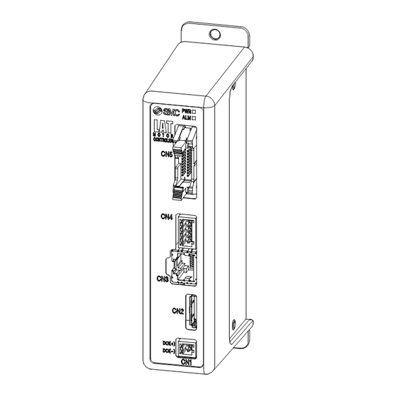
4. Hardware Specifications 4.1 Input Specifications Based on the RS485 (2-wire type) 4.2 Communication Connector Pin Assignment Connector used: Hirose Electronics 「TM11R-5M2-88」 Terminal no. Function Description Not connected Not connected SD + Connect + signal lead Note1) SD - Connect - signal lead Note1) Not connected Not connected... - Page 11 optional communication cable (LATH6-) is shown below. LATCA Communication cable LATH6- Upper level device Function White D+ (transmitted data +) (transmitted data -) Black SG (Signal ground) GND (Power supply 0V) Function DC1 (-) DC1 (+) An example of wiring when multiple controllers (e.g. 3pcs.) using optional branch communication cables (LATH7-), branch connector (LEC-CGD), branch-to-branch cables (LEC-CG2-) and communication cable (LEC-CG1-) are connected to upper level equipment such as a PLC is shown below.
-
Page 12: Software Specifications
5. Software Specifications 5.1 Serial Communication Specification The LATCA specific (command type) protocol is shown below. Criteria Description Protocol Specific to LATCA Communication data ASCII hex Node type Slave (controller) Error Check None Frame size Variable length; 128 bytes maximum RS-485;... -
Page 13: Frame Format
5.2 Frame Format The frame formats used in serial communication are listed below. (1) Frame Format (i) Requirements (upper level equipment such as PLC → Card Motor controller) Start Check Note1) Space Command Space Parameter Code Code 1 byte 2 bytes 1 byte 2 bytes 1 byte... - Page 14 (2) Guard processing of received frames If the ASCII code is broken as a result of noise in the frame received and inaccurate data is mixed, an "NG" will be sent. If only inaccurate data is received, by discarding of the received data, the frame received can be protected.
-
Page 15: Command List
5.3 Command List A list of possible commands is detailed below. When the controller is set to 'pulse input type', the available functions are limited. Pulse Command Parameter Meaning input (1) Reading Step Data The INDEX 2 parameter related to the Step-Data no. in INDEX INDEX1 1 will be read. -
Page 16: Command Details
5.4 Command Details (1) Step Data Setting Command "EE" Details Step Data values identified as "INDEX1" or "INDEX2" will be read. Step Data values identified as "INDEX1" or "INDEX2" can also be set. Please see the parameter table below for details. (i) Required Format - Data read Start... - Page 17 Data will be sent as a value to 5 decimal points. Response Data 0.00000 to 60000.00000 E.g. 1) When reading Step Data No. 1: Movement Time Command sent ":EE 3 1D2 (D2 is the checksum) Data Sent ":EEOK0.030008B" (8B is the checksum) E.g.
- Page 18 INDEX1 INDEX2 DATA Parameter Parameter Configuration Value Description Description Value Value Unit Range Unavailable Target Position [μm] Note 1) Note 1) Positioning Time [s] 0.01 0 to 60 Speed [mm/s] 0 to 400 Acceleration [mm/s 0 to 60000 Deceleration [mm/s 0 to 60000 1 to 20, Pushing Speed [mm/s]...
- Page 19 Note 1: The maximum value is the same as for the Card Motor maximum stroke [μm]. (e.g. Maximum value for the LAT3-10: 10000 [μm]) The minimum values vary depending on the movement mode as described below. Minimum value in REL operation: Card Motor stroke [μm] x -1 (e.g.
- Page 20 Note 3: Maximum values differ depending on the Card Motor model. (LAT3-10: 5.0, LAT3-20: 4.8, LAT3-30: 3.9, LAT3-50: 2.0) Note 4: Step Data 20 is used in direct operation. Note 5: If the Target Position exceeds the stroke range, the Card Motor operation speed is over 400mm/s, or any other impossible value is set, during the operation “Step Data error”...
- Page 21 (iii) Parameter Description Parameter Description Name Step Data The Step Data No. to be read and configured is defined. Target Position Configure either the target position or the thrust starting position. Configures the positioning time in which the target position is to be reached. In "Step Data input"...
- Page 22 Parameter Description Name Target position coordinates will be set. Movement Mod Details Movement The target position will be set as an absolute coordinate with Mode the Card Motor Origin point used as a reference point. The target position will be set as a relative coordinate with the current position used as a reference point.
-
Page 23: Step Data Save Command "Eu" Details
(2) Step Data Save Command "EU" Details Use after executing Step Data setting command "EE". (i) Required Format Start Check Space Command End Code Code "01"- "EU" CR, LF "FF" (ii) Response Format (a) Normal response Start Check Command Result Code Code "01"-... -
Page 24: Monitor Command "Mo" Details
(4) Monitor Command "MO" Details Execute the Return to Origin operation before using the Monitor Command. If the Monitor Command is input before the Return to Origin operation, correct information may not be acquired. (i) Required Format Start Check Space Command End Code Code... - Page 25 Formula Example) LAT3-10 (encoder resolution: 0.03mm) Data response: "000F418C" ⇒ 999,820count CardMotor table position: (1,000,000-999,820) x 0.03 mm= 5.4 mm (c) Speed data mm/s Responds with data (absolute values) on the current Card Motor movement speed. Direction is not taken into consideration. Binary digit (decimal) 0 to 1000 ASCII hex...
- Page 26 (5) Operation Instructions Method Change Command "MD" Details This changes the controller operation mode from parallel I/O to serial communication mode. (Parallel I/O operation mode using I/O signals will be activated when the power supply is turned on). When using this command, after transitioning the CardMotor controller to serial communication operation mode, execute the "OE"...
-
Page 27: Details On Operation Command "Oe"Details
(6) Operation Command "OE" Details To be able to use this command, the controller must be set to serial I/O operation mode through the "MD" command in advance. This command should also be used in both Step Data and Direct Operation modes. Select the desired Step Data number and send ACTION “0”, once ACTION “1”... - Page 28 (iii) Parameter Description STEP ENABLE ACTION Parameter Parameter Parameter Description Description Description Value Value Value Maintain Card Motor Return to Origin Current power OFF Position Step Data Operation Card Motor Operation 1 to 15 Step Data No. power ON Start Direct Operation (iv) Operation and Parameter Examples Parameter Value...
-
Page 29: Alarm History Command "Re"Details
(7) Alarm History Command "RE" Details This command reads the alarm history saved in the controller. The alarm history can be cleared by setting the parameter to "0" (sets the whole alarm history to no.0) This command can be used to check alarm details when they occur. (i) Required Format (a) Data read Start... - Page 30 (iii) Alarm No. and Name Alarm Hexadecimal Alarm name Details value No alarm Memory error Actuator cable disconnected Temperature error Motor overload error Over current error I/O signal over current error Origin parameter error Parameter error Step Data parameter error Invalid parameter error Pulse speed error Pulse input error...
-
Page 31: Error Code
5.5 Error Code The data responses received from each command is converted to binary (1byte) → ASCII (2bytes). Problems Name Description・Countermeasures Code <Description> An undefined command has been specified. ILLEGAL FUNCTION <Countermeasures> Return the command listed in 5.3 Command List. <Description>... -
Page 32: Card Motor Controller Operation Examples
6. Card Motor Controller Operation Examples 6.1 Basic Settings, I/O Configuration Set the following criteria in the controller using the controller configuration software. (See the "Card Motor Controller (Step Data input edition)" operation manual for details) - Input type (select Step Data input type) - Card Motor Mounting Orientation - Return to Origin Method - Step Data Input Method... -
Page 33: Operation Data Acquisition
6.3 Operation Data Acquisition This explains the Card Motor operation data acquisition procedure. (1) Operation data is acquired using the "MO" command. 6.4 Operation Instruction Method This explains the procedure for operation instructions to the Card Motor using serial communication. (1) Ensure the SVON signal input to the controller is turned OFF and the Card Motor power cut. -
Page 34: Program Examples
6.5 Program Examples Program examples for how to perform Basic settings and Step Data setting by serial communication are listed below. In the following examples, the response data is indicated in ASCII notation; space is indicated as “_” and command monitor contents is indicated as “**”. The checksum and end code are omitted. (1) Basic Settings Use the dedicated “LATC Configurator”... - Page 35 to Origin instructions. Data Data Requested Operation Details Responded :01_OE_0_0_0 :01OEOK Instruction to turn Card Motor power OFF sent. Instruction to change the Card Motor controller operation :01_MD_1 :01MDOK mode to "serial I/O operation" sent. :01_OE_0_1_0 :01OEOK Instruction to turn Card Motor power ON sent. :01_OE_0_1_1 :01OEOK Instruction to perform the Return to Origin operation sent.
-
Page 36: Positioning Operation (Step Data Operation) Example
(5) Positioning Operation (Step Data Operation) Example Change the Card Motor controller (controller ID1) operation mode to serial I/O operation, perform Return to Origin and repeat Step Data No.1 and 2. If returning to origin has already been completed, omit No.1 to No.6 and start from No7. Data Data Requested Operation Details... -
Page 37: Positioning Operation (Direct Operation) Example
(6) Positioning Operation (Direct Operation) Example Change the pre-configured Card Motor controller (controller ID1, Cycle Time Input Method) operation mode to serial I/O operation, perform Return to Origin and direct operation instructions are used to move the table from 5 mm to 10 mm. ... -
Page 38: Operation Data Acquisition Example
Caution The step data (e.g. target value) currently in operation will not be changed by simply changing Step Data No. 20 using only the EE command. After sending ACTION,"0'’ ("OE_20_1_0") with the OE command, and then sending action,"1’ ("OE_20_1_1"), the step data is changed and the operation begins. Configure the contents of Step Data No.20 before using Direct Operation. -
Page 39: Option(Separately Sold Products
7. Option(Separately Sold Products) 7.1 Communication cable The cable used to connect one controller to an upper level device (PLC). (1) Communication cable i. How to Order L A T H 6 - 1 Cable length ii. Dimensions iii. Wiring diagram Terminal No. -
Page 40: Branch Communication Cable
7.2 Branch communication cable The cable used to connect multiple controllers to an upper level device (PLC). (1) Branch communication cable (between an upper level device and a branch connector) i. How to order L A T H 7 - 1 Cable length ii. - Page 41 i. How to order L E C – C G 2 – L Cable length 0.3m 0.5m ii. Dimensions (4) Branch connector i. How to order L E C – C G D Branch connector ii. Dimensions (5) Terminating resistor i.
-
Page 42: Reference Information
8. Reference Information 8. 1 Checksum Calculation Procedure The checksum calculation is based on the LRC method. (1) All sent data is added, excluding the Start/End codes. (2) Subtract FFh from the last 2 bytes of the calculation result in step (1). (3) Add 1h to the calculation result in step (2). -
Page 43: Ascii Code List
8. 4 ASCII Code List Hexade Hexade Hexade Hexade Decimal ASCII Decimal ASCII Decimal ASCII Decimal ASCII cimal cimal cimal cimal " & < > -42-... - Page 44 Revision history 1st edition: December 2014 A: Revised in July 2015 B: Revised in November 2015 C: Revised in June 2020 D: Revised in January 2023 E: Revised in February 2024 Tel: + 81 3 5207 8249 Fax: +81 3 5298 5362 https://www.smcworld.com Note: Specifications are subject to change without prior notice and any obligation on the part of the manufacturer.
Need help?
Do you have a question about the LATCA Series and is the answer not in the manual?
Questions and answers