Table of Contents
Advertisement
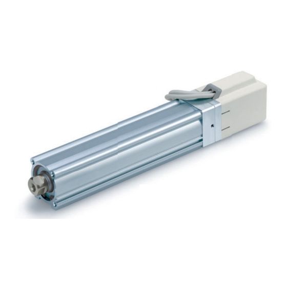
Electric Actuator / Rod Type
Applicable models: LEY[], LEYG[],
LEY Series
(Rod type)
<Controller>
LEC Series
This manual describes the actuators operation in combination with the LEC*6 series controllers.
Refer to the manual relevant to the controller being used for full operating instructions.
PRODUCT NAME
MODEL / Series / Product Number
LEY Series
LEYG Series
(Guide Rod type)
Doc. no. LEY-OM00211
Advertisement
Table of Contents

Related Manuals for SMC Networks LEYG


Summary of Contents for SMC Networks LEYG
- Page 1 Doc. no. LEY-OM00211 PRODUCT NAME Electric Actuator / Rod Type MODEL / Series / Product Number LEY Series Applicable models: LEY[], LEYG[], LEYG Series LEY Series (Guide Rod type) (Rod type) <Controller> LEC Series This manual describes the actuators operation in combination with the LEC*6 series controllers.
-
Page 2: Table Of Contents
2. Rod type / LEY Series ..............9 2.1 Specification ................9 2.2 How to Order ................11 2.3 Construction................12 3. Guide rod type / LEYG Series ............. 13 3.1 Specification ................13 3.2 How to Order ................15 3.3 Construction................16 4. -
Page 3: Safety Instructions
LEY Series / Electric Rod type Safety Instructions These safety instructions are intended to prevent hazardous situations and /or equipment damage. These instructions indicate the level of potential hazard with the labels of “Caution,” “Warning” or “Danger.” They are all important notes for safety and must be followed in addition to International Standards (ISO /IEC), Japan Industrial Standards (JIS)*1) and other safety regulations*2). - Page 4 LEY Series / Electric Rod type Safety Instructions Caution The product is provided for use in manufacturing industries. The product herein described is basically provided for peaceful use in manufacturing industries. If considering using the product in other industries, consult SMC beforehand and exchange specifications or a contract if necessary.
-
Page 5: Procedure Before Operation/Simple Setting To Use Straight Away4
Conditions Refer to power consumption of each actuator Power supply 24VDC / See 2.1Specification[LEY] on p.9, 3.1 Specification[LEYG] on p.13 Do not use the power supply with “Inruch-restraining type” (Prepare the power supply that has capacity of “Moment max.power consumption” or more.) Wire AWG20 (0.5mm... -
Page 6: Controller Setting Software Version
1.2 Controller setting software version 1. Installation of software With the controller setting software CD-ROM, install the communication unit software, following the “Software Installation procedure” (PDF) 2. Startup of software After turning on the controller power supply, start up the ACT Controller setting soft ware Select “Easy Mode”... - Page 7 4. TEST Drive / Step No.0 → No.1 → No.0・・・ a. Driving preparation: Servo On → Return to ORIG / Refer to “3.JOG Drive”. b.TEST Drive “Step No.0” Operation Procedure 2: → Operation Procedure 1: Select “Drive” Select “Step No.0” You can select anywhere in the row “Step No.1”...
-
Page 8: Teaching Box
1.3 Teaching box 1. Name (2) JOG key (3)SET key (4) Up and down, right and left key (5)MENU key (1) Number key 2. JOG Drive データ テスト モニタ EXT Inp OFF:YES Operates by (2) JOG key DATA TEST MONITOR Press the (3)SET key JOG+: extract ↓... - Page 9 4. Step data change “Step No.0” / Pushing operation / At the time of shipment, Step No.0 is set to pushing operation “Step No.0” Change of pushing データ テスト モニタ DATA TEST MONITOR start position Step Posn 50 mm → 40mm Step No.
-
Page 10: Rod Type / Ley Series
2. Rod type / LEY Series 2.1 Specification (1) Step motor (servo 24VDC) Model LEY 16 LEY 25 LEY 32 LEY 40 30, 50, 100, 150, 200, 250, 300, 350, 30, 50, 100, 150, 200, 250, 300, 350, 30, 50, 100, 150, 200, 250, 300, 350, Note1) Stroke [mm] 30, 50, 100, 150, 200, 250, 300... - Page 11 (2) Servo motor (24VDC) Model LEY 16A LEY 25A 30, 50, 100, 150, 200, 250, 300, Note1) 30, 50, 100, 150, 200, 250, 300 Stroke [mm] 350, 400 Work load Horizontal (3000[mm/s note 2) [kg] Vertical (3000[mm/s Note3)4) 16to30 30to58 57to111 18to35 37to72...
-
Page 12: How To Order
2.2 How to Order LEY B - 100 - S 1 6N 1 40 ① ② ③ ④ ⑤ ⑥ ⑦ ⑧ ⑨ ⑩ ⑪ ⑫ ⑬ ⑩ Actuator Cable length [m] ① Size ④ Lead[mm] ⑥ Motor option Without Without option LEY16 LEY25 LEY32 LEY40 symbol... -
Page 13: Construction
2.3 Construction Parts list Part Material Remarks Part Material Remarks Body Parallel pin Stainless steel Aluminum alloy Anodized High carbon chrome Ball screw shaft Rod seal bearing steel Ball screw nut Retaining ring Resin/Alloy steel Steel for spring Phosphate coated Piston Motor Aluminum alloy... -
Page 14: Guide Rod Type / Leyg Series
3. Guide rod type / LEYG Series 3.1 Specification (1) Step motor (servo 24VDC) Model LEYG 16 LEYG 25 LEYG 32 LEYG 40 Note1) Stroke [mm] 30, 50, 100, 150, 200 30, 50, 100, 150, 200, 250, 300 30, 50, 100, 150, 200, 250, 300... - Page 15 50 / 20 Note6) Resistance [m/s Drive method Ball screw and Belt Guide type Slide bearing (LEYG□M), Ball bushing bearing (LEYG□L) Operating temperature range [℃] 5 to 40 Operating humidity range [%] 90 RH or less (No condensation) □28 □42...
-
Page 16: How To Order
3.2 How to Order LEYG B - 100 - S 2 A1 16 M ① ② ③ ④ ⑤ ⑥ ⑦ ⑧ ⑨ ⑩ ⑪ ⑫ ⑬ ① Size ⑦ Motor option ⑤ Lead [mm] ⑨ Actuator cable type LEYG16 LEYG25 LEYG32 LEYG40 Without option symbol Without cable... -
Page 17: Construction
Only “With lock/motor cover” 22 Rod seal Support block Replacement Parts(Top/Parallel only)/Belt Size Order no. *Mounting bolt (2 Size Part number pieces) is included LE-D-2-1 LEYG-S016 in Support block. LE-D-2-2 LEYG-S025 32/40 LE-D-2-3 32 / 40 LEYG-S032 - 16 -... -
Page 18: Product Outline
4. Product Outline 4.1 System construction Note 1) ●I /O cable Motor cable ●Electric actuator Part No: LEC-CN5-* /Rod type Note 1) ●Controller Note 2) Power supply To CN5 24VDC Option Communication To CN4 cable To CN3 Conversion unit Note 1) ●Actuator cable Controller setting software... -
Page 19: Setting Function
4.2 Setting Function Refer to the operation manual of the controller (LEC series) for the detail of the setting function. Easy Mode for simple setting >Select “Easy mode” for instant operation Controller setting software Setting and operation, such as the step data setting, test drive and JOG / fixed-distance moving, can be performed on the same page. - Page 20 Normal mode for the detailed setting >Select “Normal mode” if the detailed setting are necessary. Step data can be set in detail. Parameters can be set. Signals and terminal condition can be monitored. JOG and fixed distance movement, return to origin position, test operation and testing of compulsory output can be done.
- Page 21 Controlled items PC: Controllersetting software TB: Teaching box ○: Available function ×: Not available function Easy Normal mode mode Function Content PC/TB ○ ○ Movement method Can be selected of absolute / relative position move × ○ ○ ○ Speed Can be set in units of 1mm/s.
-
Page 22: Step Data Setting Method
4.3 Step data setting method Refer to the operation manual of the controller (LEC series) for details. This operation manual specifies the electric actuator, if an actuator other than the electric actuator is used, refer to the operation manual of each type of actuator and controller (LEC series) regarding the description of step data. - Page 23 <Items and set values in positioning operation> Step No. 1: Positioning operation Move M Speed Position Accel Decel PushingF TriggerLV PushingSp MovingF Area1 Area2 In pos mm/s mm/s^2 mm/s^2 mm/s 0 Absolute 50.00 3000 3000 48.00 50.00 20.00 1 Absolute 0.00 3000 3000...
- Page 24 Pushing operation The rod move to the target position and hold a work piece with the set pushing force. The figure shows setting items and operation. The setting items and values are described below. <Confirmation of reaching the target value during the pushing operation> The “target position reaching signal”...
- Page 25 <Items and setting values of pushing operation> Step no. 0: Pushing operation Move M Speed Position Accel Decel PushingF TriggerLV PushingSp MovingF Area1 Area2 In pos mm/s mm/s^2 mm/s^2 mm/s 0 Absolute 50.00 3000 3000 48.00 50.00 20.00 1 Absolute 0.00 3000 3000...
- Page 26 Example of step data entry (1) 〈 Positioning operation - 【INP】output signal, 【AREA】output signal 〉 Move M Speed Position Accel Decel PushingF TriggerLV PushingSp MovingF Area1 Area2 In pos mm/s mm/s^2 mm/s^2 mm/s 0 Absolute 100.00 3000 3000 80.00 90.00 0.50 ・Step data no.0 : Positioning operation (It moves from Position:0[mm] to Position:100[mm]) Condition 1) The 【AREA】output signal is not used.
- Page 27 Example of step data entry (2) 〈 Pushing operation - 【INP】output signal, 【AREA】output signal 〉 Move M Speed Position Accel Decel PushingF TriggerLV PushingSp MovingF Area1 Area2 In pos mm/s mm/s^2 mm/s^2 mm/s 0 ABS 80.00 3000 3000 70.00 100.00 25.00 ・Step data no.0 : Positioning operation.
- Page 28 Example of step data entry (3) 〈 Positioning operation - Relative 〉 Move M Speed Position Accel Decel PushingF TriggerLV PushingSp MovingF Area1 Area2 In pos mm/s mm/s^2 mm/s^2 mm/s 0 Relative 10.00 3000 3000 10.00 20.00 0.50 1 Relative -10.00 3000 3000...
- Page 29 Example of step data entry (4) 〈 Pushing operation - In position 〉 Move M Speed Position Accel Decel PushingF TriggerLV PushingSp MovingF Area1 Area2 In pos mm/s mm/s^2 mm/s^2 mm/s 0 Absolute 20.00 3000 3000 10.00 20.00 20.00 ・Step data no.0 : Pushing operation ("Pushing operation" is done during 20mm after it moves from 0mm to 20mm.) Condition 1) Length to work <...
- Page 30 Example of step data entry (4) 〈 Pushing operation – Driving starting position 〉 The pushing action is different and dependent upon the starting position and derection. Confirm the position where the pushing operation starts. Move M Speed Position Accel Decel PushingF TriggerLV PushingSp MovingF...
- Page 31 Operating procedure and input / output signals for each operation The input / output signal and the operation description for operating this electric actuator are as follows. 1) Signals along with the operation procedures In case the operation order is 1.Supply power to the motor ...
- Page 32 2) Signals when Stopped: In the event when “EMG” is used / See 6.1 Caution (9) on p.36 The operating sequence is 1.”Stop” 2.Release the “Stop” Output signal to the input Procedure Input signal Operation description signal *ESTOP [ ] Power to the motor is cut by the “Stop”...
-
Page 33: Parameter Setting
4.4 Parameter setting Initial setting for the basic parameters Refer to the controller’s (LEC series) operation manual for detail. As the “basic parameter” is unique data of each actuator, if an actuator other than the “electric actuator / rod type” is used, refer to the operation manual of each actuator and the controller’s (LEC series) Description(Extract) Initial input value Input range... - Page 34 2) Origin offset The origin offset means the value of the origin. (“Origin offset”=origin) When the parameter “Origin offset” is changed, the value of “Stroke(+)”, “Stroke(-)” of basic parameter should be checked again. Initial input value: “Origin offset”=0 Move in the opposite direction (Moving distance 2mm / Not changeable) by the return to origin becomes "origin =0".
- Page 35 Initial setting for the ORIG parameters Refer to the controller’s (LEC series) operation manual for detail. As the “ORIG parameter” is unique data of each actuator, if an actuator other than the “electric actuator / rod type” is used, refer to the operation manual of each actuator and the controller’s (LEC series) operation manual for the ORIG parameter.
-
Page 36: Wiring Of Cables / Common Precautions
5. Wiring of cables / Common precautions Warning Adjusting, mounting or wiring change should never be done before shutting off the power supply to the product. Electrical shock, malfunction and damaged can result. Never disassemble the cable. Use only specified cables. Never connect or disconnect the cable or connector with power on. -
Page 37: Electric Actuators / Common Precautions
6. Electric actuators / Common precautions 6.1 Design and selection Warning 1. Be sure to read the Operation Manual (this manual and the one for the controller: LEC series). Handling or usage/operation other than that specified in the Operation Manual may lead to breakage and operation failure of the product. -
Page 38: Mounting
Rerutning to origin cannot be done during the operation. It cannot be done during positioning operation, pushing operation and pushing. Refer to a common auto switch /matter (Best Pneumatics No 2) when an auto switch is built in and used. When conformity to UL is required, the electric actuator and controller should be used with a UL1310 Class 2 power supply 6.2 Mounting... -
Page 39: Handling
6.3 Handling Warning Do not touch the motor while in operation. The surface temperature of the motor can increase to approx. 80 C due to operating conditions. Energizing alone may also cause this temperature increase. As it may cause burns, do not touch the motor when in operation. -
Page 40: Operating Environment
[Unpackaging] Caution 1. Check the received product is as ordered. If the different product is installed from the one ordered, injury or damage can result. 6.4 Operating environment Warning 1. Avoid use in the following environments. a. Locations where a large amount of dusts and cutting chips are airborne. b. -
Page 41: Maintenance
6.5 Maintenance Warning Do not disassemble or repair the product. Fire or electric shock can result. Contact SMC, in case of disassembly for the maintenance. Before modifying or checking the wiring, the voltage should be checked with a tester 5 minutes after the power supply is turned off. -
Page 42: Electric Actuators / Common Precautions
This can lead to premature failure of the product.. If using in a stopper application, please select the LEYG series "slide bearing". When used as a stopper, select the LEYG series ‘‘Sliding bearign’’ for a stroke of 30mm or less. - Page 43 When pushsing operation, be sure to use in "pushing operation". Also, do not hit the work piece in positioning operation or in the range of positioning operation. It causes the breakage and malfunction. Keep the specifications driving speed range for pushing operation. It causes the breakage and malfunction.
- Page 44 15. When mounting the actuator, leave a gap of 40mm or more to allow for bending of the actuator cable. 16. When using auto switch with the guide rod type LEYG series, the following limits will be in effect. Please select the product while paying attention to this.
- Page 45 17. Encloure - First characteristic numeral Second characteristic numeral ・First Characteristics:Degrees of protection against solid foreign objects Non-protected Protected against solid foreign objects of 50 mm and grater Protected against solid foreign objects of 12 mm and grater Protected against solid foreign objects of 2.5 mm and grater Protected against solid foreign objects of 1.0 mm and grater Dust-protected Dust-tight...
-
Page 46: Mounting
7.3 Mounting Caution Fix 'Socket' square width across flats in the piston rod point with the spanner etc. , prevent the piston rod from rotating, and tighten the screw tightening when work piece or jig, etc. are installed properly by the torque value within the range of the limitation. It causes the abnormal reaction of an auto switch, the space of an internal guide, and an increase of the sliding resistance, etc.. - Page 47 [LEYG series] Work fixed/ Plate tapped style Max. Max. thread Model Bolt tightening depth [mm] torque [N•m] LEYG16 M5 x 0.8 LEYG25 M6 x 1.0 LEYG32 / LEYG40 M6 x 1.0 Mounting / Upper mounting tapped style Max. Length tightening...
-
Page 48: Precaution On Maintenance
7.4 Precaution on maintenance Caution 1. Cut the power supply during maintenance and replacement of the product. [ Maintenance frequency ] Preform maintenance according to the table below. Appearance check Check belt ○ Inspection before daily operation ○ ○ Inspection every six months ○... -
Page 49: Troubleshooting
8. Troubleshooting Alarms below are abstract of representative examples. For other alarms, see operation manual of controller. Phenomenon Cause Countermeasure Fall to operate 1) The cable is not connected or Confirm that the cable is / Initial stage has been disconnected connected correctly. - Page 50 Phenomenon Cause Countermeasure 1) The lead screw had galling due Operate within the specified Operation not completed to excessive external force range. / Operation continue (including vibration) or impact. /See 2.1 Specifications on p.9-10 /See 3.1 Specifications on p.13-14 Alarm for “Over load/code: 1-148” 2) The Power supply does not Check the power consumption or “Posn failed/code: 1-149”...
- Page 51 Phenomenon Cause Countermeasure Alarm for “Pushing ALM 1) For the pushing operation, the Check the step data. /code: 1-096” is generated. position, target start-pushing /See 7.2 Caution (7) on p.42 ↓ position, is not set correctly. <Procedure of restart> Controller version /SV1.0 or later 1.
- Page 52 Phenomenon Cause Countermeasure 1) Added excessive external Operate within the specified range. Alarm for “ Err overflow force (including vibration) or /See 2.1 Specifications on p.9-10 /code: 1-196” is generated. impact load. /See 3.1 Specifications on p.13-14 ↓ <Procedure of restart> “Turn the power supply off.”...
- Page 53 Phenomenon Cause Countermeasure Operation not completed Check if the step data is valid 1) Command invalid (registered). (unregistered) step data. / During operation (Not always, but may happen Add an interval of 15ms (the 2) Different input signal to the occasionally) recommendation is 30ms) or more expected step number is...
- Page 54 Phenomenon Cause Countermeasure "Output signal" unstable the 1) "INP output signal" turns "ON" Set the "Pushing force" and the because the actual pushing "TriggerLV" within the specified "INP output signal" turns "ON" force exceeds "TriggerLV". range for the "Pushing speed" before pushing the work piece.
- Page 55 SVRE[OFF], or moved by more than the lock holding /see 2.1 Specifications/LEY on p.9 external force. force is applied. /see 3.1 Specifications/LEYG on p.13 Stop supplying 24VDC power 2) 24VDC is supplied to "BK supply to the [BK RLS] terminal RLS" terminal of /see 6.6 Precautions for the...
- Page 56 Revision history No.LEY-OM00201 Jun / 2009 1st printing No.LEY-OM00202 Apr/ 2010 Revision ・Addition / LEYG Series (Guide rod type) No.LEY-OM00206 Aug / 2010 Revision ・Addition / LEY_D (In-line mounting type) No.LEY-OM00207 Mar / 2011 Revision ・Addition / LEYG_D (In-line mounting type), LECP1 No.LEY-OM00208...
Need help?
Do you have a question about the LEYG and is the answer not in the manual?
Questions and answers