
Related Manuals for SMC Networks LAT3 Series


Summary of Contents for SMC Networks LAT3 Series
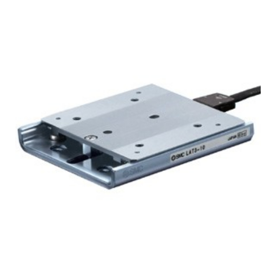
- Page 1 Doc No. LA-OMT0056-A PRODUCT NAME Card Motor Simple Setting (Step Data Input version) Model / Series / Product Number LAT3/LATCA Series Controller Series LATCA...
- Page 2 About this Operation manual This Card Motor Simple Setting manual summarizes the the installation and initial setting of the Card Motor and Controller. Refer to the Card Motor operation manual and the Card Motor Controller operation manual for further details. - 1 -...
-
Page 3: Table Of Contents
Contents 1. Safety Instructions ..............3 2. Start up procedure / Connecting to a computer ......5 2. 1 Preparation ......................5 (1) Confirmation of product ................. 5 (2) Wiring......................5 (3) Installation of the Card Motor .............. 6 (4) Prepared and wired by the user............7 (5) Software installation ................ -
Page 4: Safety Instructions
LAT3 Series/Card Motor 1. Safety Instructions These safety instructions are intended to prevent hazardous situations and/or equipment damage. These instructions indicate the level of potential hazard with the labels of "Caution", "Warning" or "Danger". They are all important notes for safety and must be followed in addition to International 1) - Page 5 LAT3 Series/Card Motor Safety Instructions Caution 1. The product is provided for use in manufacturing industries. The product herein described is basically provided for peaceful use in manufacturing industries. If considering using the product in other industries, consult SMC beforehand and exchange specifications or a contract if necessary.
-
Page 6: Start Up Procedure / Connecting To A Computer
The procedure for initial start up using a PLC are explained below. 2. 1 Preparation (1) Confirmation of product Check the part numbers on the product labels and the quantity of the accessories to confirm that the order is correct. LAT3 series Description Quantity Note Card Motor 1 pc. -
Page 7: Installation Of The Card Motor
(3) Installation of the Card Motor Points for installation of the Card Motor. 【Fixed side / moving side】 Fix the rail to the mounting surface with screws before operating the table. Table 【Mounting surface】 Keep the flatness of the mounting surface of the table and rail 0.02mm or less. -
Page 8: Prepared And Wired By The User
Warning Adjusting, mounting, inspection or changes to the wiring should never be done while power is being supplied to the product. Electrical shock, malfunction, and breakage can result. Caution Refer to the Card Motor operation manual and Card Motor Controller operation manual for detailed installation and wiring. -
Page 9: Controller Settings
2. 2 Controller settings The Card Motor model to be controlled and the controller operating conditions must be set using a computer. This operation manual describes the step data input which allows checking of the operation set by the computer. (1) Start the setup software After wiring, start the controller setting software following the flow chart below after supplying power to the controller. -
Page 10: Basic Parameter Setup
(2) Basic Parameter Setup Select the setting for each item described below using the Basic Parameter Setup window and register it to the controller by selecting [Setup]. Card Motor Product Number: Product number of the applicable Card Motor. Card Motor Mounting Orientation: Horizontal or Vertical mounting Return to Origin Method: Retracted or Extended end Origin position Step Data Input type: Cycle Time Entry Method (recommended). - Page 11 Caution Refer to the Card Motor Controller operation manual for details of the data setting procedures and buttons. The Card Motor Product Number set in the Controller Setting Software must correspond with the connected Card Motor. If they do not correspond, the Card Motor will operate at a position, speed and thrust different from the settings leading to operation failure.
-
Page 12: 3.Start Up Procedure/Test Operation Using A Computer
3.Start up procedure/Test operation using a computer 3. 1 Test operation using a computer (Step data operation) A test operation can be performed using a computer. The operating performance and the controller settings can be tested and confirmed by operating the Card Motor under the actual operating conditions using the Card Motor Controller Setting Software in “Test Mode”, as follows. - Page 13 Warning Consider the movements of the table when the Card Motor is de-energized. If [Servo On] is pressed, no power will be supplied to the Card Motor, so the table will not be fixed and can be moved by external force. Check that the table movement cannot cause aninjury or damage to the equipment.
-
Page 14: Test Operation Using A Computer (Continuous Operation)
3. 2 Test operation using a computer (Continuous operation) A continuous test operation of the Card Motor can be performed using a computer when Step Data Input type is selected. The operating performance and the controller settings can be tested and confirmed by operating the Card Motor under the actual operating conditions using the Card Motor Controller Setting Software in “Test Mode”... - Page 15 Warning Consider the table movement. If the operation has ended (power is OFF), no power will be supplied to the card motor. The table will not be fixed and can be moved by external forces or the table's own weight (including workpieces).
-
Page 16: 4.Start Up Procedure/Operation By Plc
4.Start up procedure/Operation by PLC The Card Motor operates based on input/ output signals sent from a PLC. Before operating the product using the PLC, perform the basic settings and the step data setting to the controller. (Refer to the section 2.2 Controller Setting for the setting instructions.) Turn off the Controller Setting Software after the settings have been downloaded to the controller. - Page 17 I/O cable pin assignment LATH2- I/O cable PLC side Controller CN5 side Fused(10) Fused Number of ways AWG size AWG28 LATH5- I/O cable Shield wire Controller CN5 side PLC side Shield wire Number of ways Number of ways AWG28 AWG24 AWG size AWG size LATH2-...
- Page 18 Controller Circuit (1) NPN type (2) PNP type 24 VDC 24 VDC power supply power supply for the input for the input signals signals The power The power supply can supply can be either be either polarity. polarity. Internal Internal resistance resistance 10[kΩ...
-
Page 19: 4.2 Parallel I/O Connection Check
Caution There are two types of parallel input and output for this controller; NPN type and PNP type. Please confirm the controller specification before wiring. The 24 VDC power supply for the controller (CN1), and the 24 VDC power supply for the parallel I/O (CN5) should be separate. -
Page 20: 4.3 Timing Diagram (Example)
4.3 Timing diagram (Example) The figure shows the timing diagram of operation for the selected step data input type and the PLC parallel input/ output signals used when power is supplied. Return to Origin position → Step Data No.1 → Step Data No.2 → Operation completed (The motor is de-energized)... -
Page 21: 4.4 Monitor Mode
4.4 Monitor mode The status of the parallel I/O signals, the table position, speed and pushing force can be monitored in Monitor Mode when the Card Motor is operating using a PLC to control the parallel I/O signals. A. Select "Monitor Mode" in the "Test Mode / Monitor Mode" window. It is not possible to operate the Card Motor in test mode using the parallel I/O signals from the PLC. - Page 22 Revision history printing: Revised in November 2015 A: Revised in November 2019 4-14-1, Sotokanda, Chiyoda-ku, Tokyo 101-0021 JAPAN Tel: + 81 3 5207 8249 Fax: +81 3 5298 5362 URL: https://www.smcworld.com Note: Specifications are subject to change without prior notice and any obligation on the part of the manufacturer. Windows is the registered Trademark or the Trademark of Microsoft Corporation in the United States or other countries.
Need help?
Do you have a question about the LAT3 Series and is the answer not in the manual?
Questions and answers