
Related Manuals for FMS Cessna 182


Summary of Contents for FMS Cessna 182
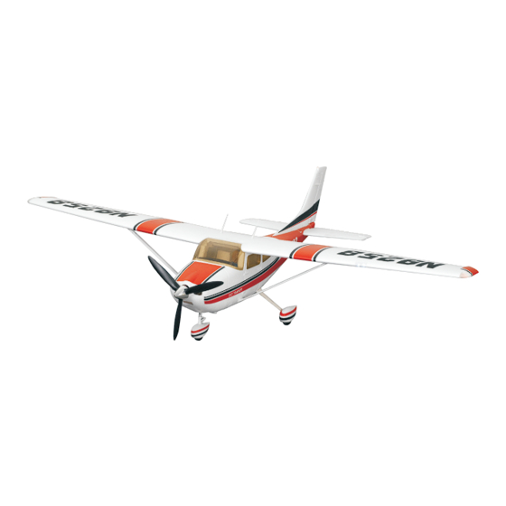
- Page 1 1500mm Cessna 182 Instruction Manual Bedienungsanleitung Manuel d’utilisation 操作手册 MAN-G0273 POWERFUL RIGID STABLE FMSHOBBY.COM 动力强劲 高强度EPO泡沫 高安定性...
- Page 2 WARNING WARNING: Read the ENTIRE instruction manual to become familiar with the features of the product before operating. Failure to operate the product correctly can result in damage to the product,personal property and cause serious injury. This is a sophisticated hobby product and NOT a toy. It must be operated with caution and common sense and failure to do so could result in injury or damage to the product or other property.
-
Page 3: Kit Contents
1956, with its development rooted assembly structure, integrated servo-connector design, and in the Cessna 180. The Cessna 182 plays a significant role in ball head control surface linkage. These measures, while general aviation due to its excellent stability, reliability, versatili- ensuring the strength and stability of the aircraft, greatly ty, flexibility, and ease of operation. -
Page 4: Model Assembly
Kit contents A: Front fuselage B: Horizontal Stabilizer C: Rear fuselage D: Supporting Struts E: Main wing set F: Vertical Stabilizer G: Landing gear set H: Spars I: Spinner J: Propeller set K: Scale antennas L: Landing gear insert ,landing gear rocker arm and screw set(HKM 3.0*10 x 7)... - Page 5 Model assembly Fuselage installation 1.Connect the servo wires of the rudder, elevator, and LED lights between the front and rear fuselages. 2.Use the attached screws (HKM3.0*10 X 2) to secure the front and rear fuselage in place from the top and bottom directions.
-
Page 6: Main Wing Installation
Model assembly 2.Insert the front landing gear into the bottom hole of the fuselage, install the landing gear rocker arm into the servo rocker arm as shown, and secure it to the landing gear aluminum part using the attached screw(HKM3.0*10 X 1). HKM 3.0*10 Main wing installation 1.Install the main wing connecting spar into the corresponding... -
Page 7: Propeller Installation
Model assembly 3. Insert the two ends of the left and right wing struts into the corresponding plastic slots on the fuselage and main wing respectively, then slide them towards the tail to secure in place. Realistic antenna installation Insert the included realistic antenna into the respective slots on the fuselage and wings, then slide them towards the tail to secure in place. -
Page 8: Battery Installation
Battery installation 1. Apply the hook tape to the cable end of the battery. 2. Slide the battery into the battery hatch with the power supply cable toward the rear end of the plane and the hook tape facing the bottom of the battery hatch. Note: You may need to relocate the battery position to acheieve the correct CG for your model. -
Page 9: Get Your Model Ready To Fly
Get your model ready to fly Transmitter and model setup Before getting started, bind your receiver with your transmitter. Please refer to your transmitter manual for proper operation. CAUTION: To prevent personal injury, DO NOT install the propel - Bank left ler assembly onto the motor shaft while testing the control surfac - es. -
Page 10: Control Horn And Servo Arm Settings
Control horn and servo arm settings The table shows the factory settings for the control More control throw Horns Arms horns and servo arms. Fly the aircraft at the factory settings before making changes. After flying, you may choose to adjust the linkage positions for the desired control response. -
Page 11: Before Flying The Model
Before flying the model Find a suitable flying site Find a flying site clear of buildings, trees, power lines and other obstructions. Until you know how much area will be required and have mastered flying your plane in confined spaces, choose a site which is at least the size of two to three football fields - a flying field specifically for R/C planes is best. -
Page 12: Troubleshooting
Flying course Landing Land the model when you hear the motor pulsing (LVC) or if you notice a reduction in power. If using a transmitter with a timer, set the timer so you have enough flight time to make several landing approaches. The model’s three point landing gear allows the model to land on hard surfaces. -
Page 13: Spare Parts List Content
Spare parts list content FMSET101BU FMSPROP078 11x6 (3-blade) propeller Fuselage FMSDJX015 Motor Mount FMSET102BU Main Wing Set Motor Board FMSET103BU Vertical Stabilizer FMSBMX011 3541 motor shaft FMSET104BU Horizontal Stabilizer FMSDZX022 3541 KV840 motor FMSET105BU Cowl PRKVX840 "40A ESC FMSET106 Spinner PRESC001 FMSET107 LED set... -
Page 14: Important Warnings
Brushless ESC Introduction Important warnings ZTW is not responsible for your use of this product, or any damage or injuries you may cause or sustain as a result of its usage. Always place safety as priority when you use the product. An electric motor that is connected in combination with a battery and/or ESC may start unexpectedly and cause serious damage and so should always be used with care and respect. -
Page 15: Throttle Calibration
Brushless ESC Introduction Throttle calibration (Important: Please make the throttle calibration for the first time using ESC!!!) Turn on the trans- The motor will beep for Connect the battery pack mitter, move the twice, then move the throttle to the ESC and wait for throttle stick to stick to the bottom position in about 2 seconds. -
Page 16: Entering The Programming Mode
Brushless ESC Introduction Cut Off power: When the voltage drops to the set low-voltage protection threshold, the ESC will cut off the power immediately. 9.40A\50A\60A\80A\100A ESCs have adjustable SBEC 5V/6V, the default set is 5.0V. 10.Acceleration: Normal/Soft Entering the programming mode 1. -
Page 17: Protection Function
Brushless ESC Introduction Programming tone reference table “beep.beep “beep.beep “beep- - “beep- - Tones “beep” “beep.beep” “beep- -” .beep” .beep.beep” beep” beep.beep” Items 1short tone 2short tone 3short tone 4short tone 1long 1long 1short 1long 2short SMR Function *OFF Brake Type *OFF Soft Brake Mid Brake... - Page 18 Brushless ESC Introduction Trouble shooting Trouble Possible Reason Action After powering up, ESC ESC doesn't set throttle range. Set throttle range again. emits the sound of battery cells, but motor can't run. After powering up, motor 1.Bad connection between ESC and battery. 1.Clean the connectors or replace them, doesn't run and doesn't check the connection polarity.
- Page 19 Warnhinweise WARNUNG: Lesen Sie die GESAMTE Bedienungsanleitung, um sich vor der Inbetriebnahme mit den Funktionen des Produkts vertraut zu machen. Wenn das Produkt nicht ordnungsgemäß bedient wird, kann dies zu Schäden am Produkt oder persönlichem Eigentum führen und schwere Verletzungen verursachen.Dieses Produkt ist kein Spielzeug! Es muss mit Vorsicht und gesundem Menschenver- stand betrieben werden.
- Page 20 Foshan Zhengze Model Technology Co., Ltd. Tel:+86-0757-26330080 E-mail:support@fmsmodel.com Add: Unit A, Building 6, Jicheng Science and Technology Innovation Park, Shunde, Foshan City, Guangdong Province, 528306 佛山市正泽模型科技有限公司 电话: 86-0757-26330080 邮箱: support@fmsmodel.com 地址及电话: 广东省佛山市顺德区北滘镇顺江社区三乐东路25号集成科创园 6栋 中国代理 车模 航模 酷乐派模型 KLP Racing 苏州雷飞航模车模 蓝飞驰模型...
- Page 21 MADE IN CHINA...
Need help?
Do you have a question about the Cessna 182 and is the answer not in the manual?
Questions and answers