
Related Manuals for FMS F-16 Fighting Falcon V2


Summary of Contents for FMS F-16 Fighting Falcon V2
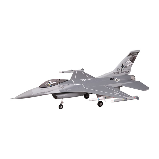
- Page 1 64MM F-16 Fighting Falcon V2 SIMPLE RIGID STABLE FMSMODEL.COM Simple assembly STRONG DURABLE EPO SMOOTH FLYING PERFORMANCE...
-
Page 4: Table Of Contents
Table of Contents Introductions ··························································································································3 Contents of Kit ························································································································4 Assemble the plane ·················································································································5 Battery and radio installation ·····································································································9 Get your model ready to fly ·····································································································10 The transmitter and model setup ······························································································11 Check the control throws ········································································································11 Clevis Installation ··················································································································12 Control Horn and Servo Arm Settings ·························································································12 Install the propeller and spinner ································································································12... -
Page 5: Contents Of Kit
Contents of Kit Before assembly, please inspect the contents of the kit. The photo below details the contents of the kit and labels. If any parts are missing or defective, please indentify the name or part number (refer to the spare parts list near the end of the manual) then contact your local shop or email us: support@fmsmodel.com A: Main Fuselage : Bomb... -
Page 6: Assemble The Plane
Horizontal Tail Installation 1. Glue the air speed head on the nose cone. Ensure the air speed head and nose cone are in perfect alignment (fig1). Required Adhesives: Medium CA fig1 2. Apply the nose cone to the front fuselage as diagram shows. Ensure the nose cone is on the correct side (fig2). - Page 7 4. The bottom of the fuselage faces up. Carefully apply CA to the base and side of the rear fuselage slot. Install the stabilizer into place. Ensure the control horn is face up as shown (fig5). Note: Ensure the stabilizer horizontal axis is parallel to the wing as shown (fig6). Adjust any misalignment before the glue dries thoroughly.
- Page 8 Install the wing Slide the wing tube into the fuselage (fig8). Install the left and right wing over the wing tube and into the wing slot of the fuselage (fig9). Secure the left and right wings to the fuselage using the included 4 screws (fig10). fig8 fig8 fig9...
- Page 9 7. Install the front and main landing gear with the included screws (fig11/fig12). KA 2.0x8 Hex screws 3*4 fig11 fig12 fig11 8. Correctly mount the wing tip missiles with glue. The missiles are correctly mounted when the top of the missiles are level with the surface of the main wing (fig13/fig14).
-
Page 10: Battery And Radio Installation
Battery and radio installation fig16 fig16 fig17 fig17... -
Page 11: Get Your Model Ready To Fly
Get your model ready to fly Important ESC and model information The ESC included with the model has a safe start. If the motor battery is connected to the ESC and the throt- tle stick is not in the low throttle or off position, the motor will not start until the throttle stick is moved to the low throttle or off position. -
Page 12: The Transmitter And Model Setup
Check the control throws The suggested control throw settings for FMS MODEL are as follows (dual rate setting): Tips: On the first flight, fly the model in low rate. The first time you use high rates, be sure to fly at low to medium... -
Page 13: Clevis Installation
Clevis Installation a. Pull the tube from the clevis to the linkage. b. Carefully spread the clevis, then insert the clevis pin into the desired hole in the control horn. c. Move the tube to hold the clevis on the control horn. Control Horn and Servo Arm Settings The table shows the factory settings for the control horns and servo arms. -
Page 14: Center Of Gravity
Check the C.G. (Center of Gravity) When balancing your model, adjust the motor battery as necessary so the model is level or slightly nose down. This is the correct balance point for your model. After the first flights, the CG position can be adjusted for your personal preference. -
Page 15: Before Flying The Model
Before flying the model Find a suitable flying site Find a flying site clear of buildings, trees, power lines and other obstructions. Until you know how much area will be required and have mastered flying your plane in confined spaces, choose a site which is at least the size of two to three football fields - a flying field specifically for R/C planes is best. -
Page 16: Flying Course
Flying course Take off While applying power, slowly steer to keep the model straight. The model should accelerate quickly. As the model gains flight speed you will want to climb at a steady and even rate. F-16 will climb out at a nice angle of attack (AOA). -
Page 17: Troubleshooting
Troubleshooting... -
Page 18: Spare Parts List Content
Spare parts list content ROCKN101 Fuselage ROCKN102 Main Wing Set ROCKN103 Horizontal Stabilizer ROCKN104 Vertical Stabilizer ROCKN105 Nose Cone ROCKN106 Canopy ROCKN107 Ventral Fin ROCKN108 Fuel Tanks ROCKN109 Missile A ROCKN110 Missile B ROCKN111 Linkage Rod ROCKN112 Landing Gear Set ROCKN113 Air Speed Head FMS64MM11B 64mm Ducted Fan... -
Page 19: Esc Instruction
ESC instruction Wires Connection: The electronic speed controller can be connected to the motor by soldering directly, or with high quality connectors. Always use new connectors, which should be soldered carefully to the cables and insulated with heat shrink tubes. The maximum length of the battery pack wires should be within 6 inches. - Page 20 Our ESC allows you to program parameters to fit your specific needs: 1. User programmable brake setting (we recommend using brake for only folding props applications) 2. User programmable battery type (LiPo or NiCd/NiMh) 3. User programmable low voltage cutoff setting 4.
- Page 21 5. Timing setup: Automatic / Low / High. * Automatic – ESC automatically determines the optimum motor timing * Low (7-22 deg) – Setting for most 2 pole motors. * High (22-30 deg)-setting for motors with 6 or more poles. In most cases, automatic timing works well for all types of motors.
- Page 22 Using Your New ESC Improper polarity or short circuit will damage the ESC therefore it is your responsibility to double check all plugs for proper polarity and firm fit BEFORE connecting the battery pack. Alert Tones The ESC is equipped with audible alert tones to indicate abnormal conditions at power up. If the ESC can't enter into working mode after powering up, it indicates that you have not setup throttle calibration.
- Page 23 Built-in Intelligent ESC Safety Functions 1. Over-heat protection: When the temperature of ESC exceeds 110 deg C, the ESC will reduce the output power to allow it too cool. 2. Lost Throttle signal protection: The ESC will automatically reduces output power to the motor when it detects a lost of throttle signal for 2 second, a subsequent loss of throttle signal beyond 2 seconds, will cause the ESC automatically to cut power to the motor.
- Page 24 ●Never use ruptured or punctured battery cells. ●Never use battery packs that are known to overheat. ●Never short circuit battery or motor terminals. ●Always use proper insulation material for cable insulation. ●Always use proper cable connectors. ●Do not exceed the number of cells or servos specified by the ESC. Wrong battery polarity will damage the ESC and void the warranty.
- Page 25 Motor doesn’t work after powering up Check and verify that the ESC cable The ESC is unable to detect the the ESC. An alert tone with a single is connected to the Throttle channel normal throttle signal from the receiver beeping tone followed by a short on the receiver.
Need help?
Do you have a question about the F-16 Fighting Falcon V2 and is the answer not in the manual?
Questions and answers