
Related Manuals for FMS A-10 Thunderbolt II V2


Summary of Contents for FMS A-10 Thunderbolt II V2
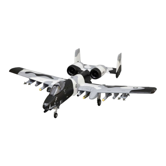
- Page 1 70mm A-10 Thunderbolt II V2 FMSMODEL.COM REALISTIC STABLE RIGID Retracts & Flaps installed Smooth flying performance Strong durable EPO material...
- Page 2 WARNING WARNING: Read the ENTIRE instruction manual to become familiar with the features of the product before operating. Failure to operate the product correctly can result in damage to the product,personal property and cause serious injury. This is a sophisticated hobby product and NOT a toy. It must be operated with caution and common sense and failure to do so could result in injury or damage to the product or other property.
-
Page 3: Table Of Contents
• Large diameter bearings in the landing gear allow the A-10 V2 to roll smoothly over rough terrain. • Preinstalled ball-linked control horns for accurate and precise movements. Feel the FMS difference! No detail was overlooked in creating the A-10 V2! Feel the power and turn every head at the flying field with your very own “Warthog”. -
Page 4: Model Assembly
A: Fuselage Vertical stabilizers G: Carbon fiber spars B: Main wing E: Missile set H: Screws C: Horizontal stabilizer F: Canopy I : Ventral fins and pitot tubes Model assembly Canopy installation 1.Install the canopy as shown. Main wing installation 1.Slide the wing spars into the fuselage. - Page 5 Model assembly Horizontal and stabilizers installation 1. Connect the rudder servo connectors to the servo extensions in the elevator . 2. Complete the tail assembly by attaching the vertical stabilizers to the slots located on the horizontal stabilizer. HKM3.0*16 3.Secure the two vertical tail pieces (left and right) in place using the 4 screws included.
- Page 6 Model assembly 5.Attach the tail assembly to the fuselage using 4 screws. The screws must be securely tightened prior to flight. HKM3.0*20 Missile set installation 1. Slide the missiles into the rails. Note:the missile rails are angled differently due to the shape of the wing structure.
- Page 7 Model assembly ventral fins and pitot tube installation 1.Screw the pitot tube in place. 2.Slide ventral fins into the rails. Required Adhesives: Foam Safe Medium CA 3. Insert the plastic part by CA as shown. Required Adhesives: Foam Safe Medium CA...
-
Page 8: Battery Installation
Model assembly 4.Insert the foaming part by CA as shown. Required Adhesives: Foam Safe Medium CA Battery installation 1. Remove the canopy. 2. Remove the hook and loop tape from the fuselage. Apply the looped surface to the battery. 3. Install the battery into the fuselage- securing it with the preinstalled battery straps. -
Page 9: Receiver Diagram
Receiver diagram The cables from the servo connector board should be connected to your receiver in the order shown. Note that the LEDs can be powered by any spare channel on the receiver. Tuck the wire leads into the recessed cavity towards the rear of the battery hatch. - Page 10 Steer right Control throws The suggested control throw setting for the A-10 Thunderbolt II V2 are as follows (dual rate setting): Tips: On the first flight, fly the model in low rate. The first time you use high rates, be sure to fly at low to medium speeds.
-
Page 11: Clevis Installation
Clevis installation 1.Pull the tube from the clevis to the linkage. 2.Carefully spread the clevis, then insert the clevis pin into the desired hole in the control horn. 3.Move the tube to hold the clevis on the control horn. Control horn and servo arm settings More control throw Horns Arms... -
Page 12: Before Flying The Model
Before flying the model Flying course Find a suitable flying site Take off While applying power, slowly steer to keep the model straight. Find a flying site clear of buildings, trees, power lines and The model should accelerate quickly. As the model gains flight other obstructions. -
Page 13: Troubleshooting
Trouble shooting Problem Possible Cause Solution Aircraft will not respond to -Lower throttle stick and throttle trim to lowest settings. -ESC is not armed. the throttlebut responds to -Reverse throttle channel on transmitter. -Throttle channel is reversed. other controls. -Damaged spinner, propeller, -Replace damaged parts.
Need help?
Do you have a question about the A-10 Thunderbolt II V2 and is the answer not in the manual?
Questions and answers