
Related Manuals for FMS RocHobby Super Viper 70MM


Summary of Contents for FMS RocHobby Super Viper 70MM
- Page 1 70MM Super Viper FMSMODEL.COM REALISTIC RIGID STABLE RETRACTS INSTALLED STRONG DURABLE EPO SMOOTH FLYING PERFORMANCE...
- Page 3 WARNING: Read the ENTIRE instruction manual to become familiar with the features of the product before operating. Failure to operate the product correctly can result in damage to the product,personal property and cause serious injury. This is a sophisticated hobby product and NOT a toy. It must be operated with caution and common sense and failure to do so could result in injury or damage to the product or other property.
-
Page 4: Table Of Contents
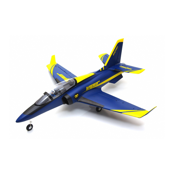
·····················································································································18 Introductions Building on engineering innovations seen in this popular jet model, ROCHOBBY(by FMS) has launched a brand new 70mm EDF Super Viper onto the market! In terms of appearance, the Super Viper has a scaled navy blue color scheme with bright yellow wingtips, which highly distinguishes it for long distance viewing. -
Page 5: Contents Of Kit
Wingspan: 1100mm(43.3in) Overall Length: 1025mm(40.5in) Flying Weight: Around 1795g(63.32oz) Motor Size: Brushless 2860-KV1850 Wing Load: 93.5 g/dm²(0.21oz/in²) Wing Area: 19.2 dm²(297.6sp.in) ESC: 70A Servo: 9g Servo x 6 Recommended Battery: 22.2V 3300mAh 35C Contents of Kit Before assembly, please inspect the contents of the kit. The photo below details the contents of the kit and labels. -
Page 6: Model Assembly
Model Assembly Main Wing Installation 1. Remove the canopy hatch 2.Guide the Y-harnesses from main wing through the hole located in the bottom of the fuselage as shown (fig1) 3.Aligh the wing with the fuselage and secure into position using screws included as shown(fig2) fig1 3.0*16 fig2... - Page 7 Model Assembly Horizontal Stabilizer Installation: 1.Connect the elevator servo connectors to the servo extensions in the fuselage. 2.Install the horizontal tail in the rear of the fuselage. Ensure the control horn faces down as shown. (fig3) 3.Secure the horizontal tail in place using the included screws. (fig4) fig3 HKM3.0*16 fig4...
- Page 8 Model Assembly Vertical Stabilizer Installation: 1.Connect the rudder servo connectors to the servo extensions in the fuselage. 2.Install the vertical tail into the slot in the fuselage. (fig5) 3.Secure the vertical tail in place using the included screws. (fig6) fig5 HKM3.0*16 fig6...
- Page 9 Flap Option 1. Cut apart the joints with a knife as shown(fig7). 2.Take out the foam blocks from the flap servo slots and put the flap servos in. (fig8) 3. Glue the control horns. 4. Install the linkage rods.(fig9) fig7 fig8 Required Adhesives: Foam Safe Medium CA...
-
Page 10: Battery Installation
Battery installation 1. Apply the hook tape to the cable end of the battery.(fig 10) 2. Slide the battery into the battery hatch with the power supply cable toward the rear end of the plane and the hook tape facing the bottom of the battery hatch. Note: You may need to relocate the battery position to acheieve the correct CG for your model. -
Page 11: Get Your Model Ready To Fly
Get your model ready to fly Important ESC and model information The ESC included with the model has a safe start. If the motor battery is connected to the ESC and the throt- tle stick is not in the low throttle or off position, the motor will not start until the throttle stick is moved to the low throttle or off position. -
Page 12: Check The Control Throws
Check the control throws The suggested control throw setting for FMS MODEL are as follows (dual rate setting): Tips: On first flight, fly the model in low rate. The first time you use high rates, be sure to fly at low... -
Page 13: Clevis Installation
More control throw Horns Arms Elevator Rudder Less control throw Ailerons... -
Page 14: Center Of Gravity
Check the C.G. (Center of Gravity) When balancing your model, adjust the battery as necessary so the model is level or slightly nose down. This is the correct balance point for your model. After the first flights, the CG position can be adjusted for your personal preference. -
Page 15: Before Flying The Model
Before flying the model Find a suitable flying site Find a flying site clear of buildings, trees, power lines and other obstructions. Until you know how much area will be required and have mastered flying your plane in confined spaces, choose a site which is at least the size of two to three football fields - a flying field specifically for R/C planes is best. -
Page 16: Flying Course
Flying Course Take off While applying power, slowly steer to keep the model straight. The model should accelerate quickly. As the model gains flight speed you will want to climb at a steady and even rate. It will climb out at a nice angle of attack (AOA). -
Page 17: Troubleshooting
Trouble shooting... -
Page 18: Spare Parts List Content
Spare parts list content ROCKP101 Fuselage ROCKP102 Main Wing Set ROCKP103 Vertical Stabilizer ROCKP104 Horizontal Stabilizer ROCKP105 Cockpit ROCKP106 Front Landing Gear Set ROCKP107 Main Landing Gear Set ROCKP108 Front Landing Gear System ROCKP109 Main Landing Gear System ROCKP110 Landing Gear Cover ROCKP111 Linkage Rod ROCKP112... -
Page 19: Esc Instruction
ESC instruction Wires Connection: The electronic speed controller can be connected to the motor by soldering directly, or with high quality connectors. Always use new connectors, which should be soldered carefully to the cables and insulated with heat shrink tubes. The maximum length of the battery pack wires should be within 6 inches. - Page 20 Our ESC allows you to program parameters to fit your specific needs: 1. User programmable brake setting (we recommend using brake for only folding props applications) 2. User programmable battery type (LiPo or NiCd/NiMh) 3. User programmable low voltage cutoff setting 4.
- Page 21 5. Timing setup: Automatic / Low / High. * Automatic – ESC automatically determines the optimum motor timing * Low (7-22 deg) – Setting for most 2 pole motors. * High (22-30 deg)-setting for motors with 6 or more poles. In most cases, automatic timing works well for all types of motors.
- Page 22 Using Your New ESC Improper polarity or short circuit will damage the ESC therefore it is your responsibility to double check all plugs for proper polarity and firm fit BEFORE connecting the battery pack. Alert Tones The ESC is equipped with audible alert tones to indicate abnormal conditions at power up. If the ESC can't enter into working mode after powering up, it indicates that you have not setup throttle calibration.
- Page 23 Built-in Intelligent ESC Safety Functions 1. Over-heat protection: When the temperature of ESC exceeds 110 deg C, the ESC will reduce the output power to allow it too cool. 2. Lost Throttle signal protection: The ESC will automatically reduces output power to the motor when it detects a lost of throttle signal for 2 second, a subsequent loss of throttle signal beyond 2 seconds, will cause the ESC automatically to cut power to the motor.
- Page 24 ●Never use ruptured or punctured battery cells. ●Never use battery packs that are known to overheat. ●Never short circuit battery or motor terminals. ●Always use proper insulation material for cable insulation. ●Always use proper cable connectors. ●Do not exceed the number of cells or servos specified by the ESC. Wrong battery polarity will damage the ESC and void the warranty.
- Page 25 Motor doesn’t work after powering up Check and verify that the ESC cable The ESC is unable to detect the the ESC. An alert tone with a single is connected to the Throttle channel normal throttle signal from the receiver beeping tone followed by a short on the receiver.
Need help?
Do you have a question about the RocHobby Super Viper 70MM and is the answer not in the manual?
Questions and answers