Advertisement
Quick Links
ETC Reference Guide
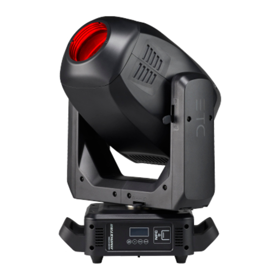
High End Systems Ministar Replacement Gobo
Overview
CAUTION:
ATTENTION :
l'entretien.
This guide provides instructions for replacing rotating gobos in the High End Systems Ministar
fixture.
Each Ministar fixture includes two gobo wheels that are located in the effects module:
• The rotating gobo wheel faces the LED engine and contains replaceable gobos.
• The fixed gobo wheel is located closest to the lens and contains gobo patterns that cannot be
replaced.
Considerations for Custom Gobos
This section includes information about the mandatory use of mounting rings for custom
rotating gobos, gobo sizing requirements, and installation positions of rotating gobo carriers.
Gobo Specifications
ETC recommends that custom gobos for use in a Ministar fixture be 1.1 mm glass BOROFLOAT
0.5 mm aluminum material.
When looking at the gobo from the LED engine, the gobo artwork must be flipped horizontally, as
shown in the graphic that follow, because the artwork is flipped horizontally when it is projected.
A R T W O R K
Corporate Headquarters n Middleton, WI, USA | +1 608 831 4116
Global Offices n London, UK | Rome, IT | Holzkirchen, DE | Paris, FR | Hong Kong | Dubai, UAE | Singapore
New York, NY | Orlando, FL | Los Angeles, CA | Austin, TX | © 2024 Electronic Theatre Controls, Inc.
Web
Trademark and patent info:
Product information and specifications subject to change. ETC intends this document to be provided in its entirety.
2540M2410 Rev A Released 2024-03
RISK OF ELECTRIC SHOCK! Disconnect power before servicing.
RISQUE DE CHOC ÉLECTRIQUE! Couper l'alimentation avant
etcconnect.com
| Support
support.etcconnect.com
etcconnect.com/ip
| Contact
etcconnect.com/contactETC
| Third-party license agreement
info: etcconnect.com/licenses
®
or
Advertisement

Subscribe to Our Youtube Channel
Related Manuals for ETC Ministar Gobo


Summary of Contents for ETC Ministar Gobo
- Page 1 Gobo Specifications ® ETC recommends that custom gobos for use in a Ministar fixture be 1.1 mm glass BOROFLOAT 0.5 mm aluminum material. When looking at the gobo from the LED engine, the gobo artwork must be flipped horizontally, as shown in the graphic that follow, because the artwork is flipped horizontally when it is projected.
- Page 2 When installing a custom glass rotating gobo, you must use a metal gobo mounting ring to help secure the gobo in the gobo carrier. Gobo mounting rings are available for purchase from ETC. Contact ETC or your authorized ETC dealer and order part number 2540A4029.
-
Page 3: Gobo Orientation
ETC Reference Guide Ministar Replacement Gobo Rotating Gobo Carriers Ministar fixtures use two different rotating gobo carriers: A standard carrier with a magnet, and a standard carrier without a magnet. Gobo Wheel Magnet Part Number Description 2540A4003 Gobo carrier, no magnet... - Page 4 ETC Reference Guide Ministar Replacement Gobo Replace a Gobo Note: ETC recommends that you wear clean cotton gloves when changing gobos to protect the gobos from dirt and fingerprints. Parts and tools required: • #2 Phillips screwdriver • Replacement gobo •...
- Page 5 ETC Reference Guide Ministar Replacement Gobo 5. Remove the gobo from the gobo carrier. a. Use a precision flatblade screwdriver to carefully pry the spring out of the gobo carrier. b. Remove the gobo from the gobo carrier. 6. Insert the new gobo into the gobo carrier.
- Page 6 ETC Reference Guide Ministar Replacement Gobo 8. Each gobo carrier has a small index spot located adjacent to the notch in the gobo carrier (#3 in the following graphic). To ensure proper rotation of the gobos with respect to each other, the index spot on each gobo carrier in the gobo wheel must be aligned with the sun gear (central hub) before you install the new gobo.
- Page 7 ETC Reference Guide Ministar Replacement Gobo 11. Reinstall the head cover. a. Align the head cover with the fixture and reattach the safety laynard to the fixture. b. Angle the cover under the front housing. c. Slide the back of the cover down and align its edges with the edges of the other cover.
Need help?
Do you have a question about the Ministar Gobo and is the answer not in the manual?
Questions and answers