
Related Manuals for Hoymiles HYS-LV-EUG2 Series


Summary of Contents for Hoymiles HYS-LV-EUG2 Series
- Page 1 Open Energy for All Single-phase Hybrid Inverter USER MANUAL HYS-8.0LV-EUG2 HYS-10.0LV-EUG2 HYS-12.0LV-EUG2 Region: Global REV1.1 hoymiles.com...
-
Page 2: Table Of Contents
3.4.7.6 DTS Connection 3.4.8 Installing the Wiring Box Cover 3.5 Operation 3.5.1 Commissioning 3.5.2 Decommissioning 3.5.3 S-Miles Cloud App 3.5.3.1 DTS Online Setting 3.5.3.2 System Commissioning of Wireless Access Point (AP) Connection © 2024 Hoymiles Power Electronics Inc. All rights reserved. - Page 3 Hybrid Inverter User Manual 4. Troubleshooting 5. Technical Datasheet © 2024 Hoymiles Power Electronics Inc. All rights reserved.
-
Page 4: Safety Introduction
After the inverter is turned off, wait for at least 5 minutes before opening the inverter or touching live parts. 5min Products shall not be disposed as household waste. CE mark. © 2024 Hoymiles Power Electronics Inc. All rights reserved. -
Page 5: Safety Information
Safety instructions in this manual cannot cover all precautions that should be taken. Please consider the actual conditions when performing operations. Any damage caused by a violation of the safety instructions in this manual shall not be the responsibility of Hoymiles. Symbol... - Page 6 Please keep the user manual properly. • The manual contains no instructions for user-serviceable parts. See Warranty for instructions on obtaining service. • If an error occurs, contact your local distributor or qualified electricians. © 2024 Hoymiles Power Electronics Inc. All rights reserved.
-
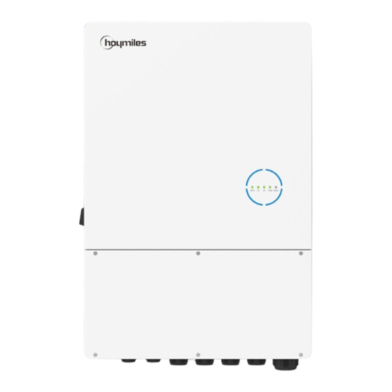
Page 7: Product Introduction
* The image shown here is for reference only. The actual product received may differ. Object Description LED Indicators DC Switch PV Terminals Communication Port Battery Terminals Grounding Bar AC Terminals © 2024 Hoymiles Power Electronics Inc. All rights reserved. -
Page 8: Product Dimensions
Hybrid Inverter User Manual 2.2 Product Dimensions 518.5 mm 502 mm 202 mm 740 mm COM FAULT 770.5 mm DC SWITCH GRID BAT+ BAT- COM1 COM2 © 2024 Hoymiles Power Electronics Inc. All rights reserved. -
Page 9: Led Indicators
1/4 circle LED on – SOC is 0-25%; battery is discharging or in standby COM FAULT 1/4 circle LED blinks – SOC is 0-25%; battery is charging Full circle LEDs off – No BMS communication COM FAULT © 2024 Hoymiles Power Electronics Inc. All rights reserved. - Page 10 On – Both meter and BMS communications are normal Off – No fault On - A fault occurs FAULT Blink 1 – EPS port overload Blink 2 – ISO/RCD fault Blink 3 – Arc fault © 2024 Hoymiles Power Electronics Inc. All rights reserved.
-
Page 11: Operating Modes
The battery can be forced to charge from the grid during the Economic Mode preset charge time. For instance, the battery could be charged or discharged according to valley or peak electricity price. © 2024 Hoymiles Power Electronics Inc. All rights reserved. - Page 12 PV surplus power selling Discharge stopped when set SOC is Consuming from grid reached Loads Battery charging Self consuming (PV power generation) 24:00 00:00 standby charging standby discharging standby Power flow of backup mode © 2024 Hoymiles Power Electronics Inc. All rights reserved.
-
Page 13: System Diagram
• Please refer to https://www.hoymiles.com for the compatible battery list, and the user should first contact Hoymiles for technical consultation and obtain official confirmation before installing any battery not included in the official published list. • Lead-acid battery is not recommended for general customers as it requires... -
Page 14: Basic Diagram
If the generator has integrated a readily accessible internal AC breaker, then no additional ② AC breaker is required. • • ⑦⑧ 30 mA RCD is recommended but not mandatory; please comply with local regulations. © 2024 Hoymiles Power Electronics Inc. All rights reserved. - Page 15 If the generator has integrated a readily accessible internal AC breaker, then no additional ② AC breaker is required. • • ⑦⑧ 30 mA RCD is recommended but not mandatory; please comply with local regulations. © 2024 Hoymiles Power Electronics Inc. All rights reserved.
-
Page 16: Unacceptable Diagram
Single PV cannot be connected to multiple inverters. Neither EPS or on-grid port can be connected to generator directly. Incompatible battery EPS port cannot be connected to grid directly. Incompatible battery cannot be connected to battery port. © 2024 Hoymiles Power Electronics Inc. All rights reserved. -
Page 17: Installation Instruction
The following tools are recommended in the installation process, and other auxiliary tools can also be used on site if necessary. Hammer drill Screwdriver Wire stripper Network cable crimper Protective goggles Safety gloves Dust mask Safety shoes © 2024 Hoymiles Power Electronics Inc. All rights reserved. -
Page 18: Mounting
7. The inverter should be installed at eye level for convenient maintenance. 8. The product label on the inverter should be visible after installation. 9. The inverter should be installed far from flammable materials. © 2024 Hoymiles Power Electronics Inc. All rights reserved. -
Page 19: Mounting Inverter
• Mount the inverter on the bracket. Step 5&6 • Tighten the screw with a torque of 1.4 N·m to secure the bracket and the inverter. © 2024 Hoymiles Power Electronics Inc. All rights reserved. -
Page 20: Electrical Connection
It is mandatory for the qualified personnel to wear personal protective equipment (PPE) during the electrical work. WARNING 3.4.1 Recommended Cable List This data is the cable specification recommended by Hoymiles, and for proper cable specification, please refer to local laws and regulations and actual installation. Specification Stripping Length Cable (90℃/194℉, Copper) -
Page 21: Ground Cable Connection
First insert the PV cable into the terminals according to positive and negative polarity, Step 2 and then gently pull the cables backward to ensure that they are firmly connected. PV1+ PV1- PV2+ PV2- PV1+ PV1- PV2+ PV2- 13-14 mm 13-14 mm © 2024 Hoymiles Power Electronics Inc. All rights reserved. -
Page 22: Battery Cable Connection
For batteries without a built-in DC breaker, make sure that an external DC breaker is connected. If you need to use this hybrid inverter as a grid-tied inverter, please contact Hoymiles for help. •... -
Page 23: Ac Cable Connection
Gently pull the grid L/N/PE cables backward to ensure that they are firmly connected. 3 N·m 17-18 mm BATT+ 17-18 mm BATT- 10-12 mm GRID S=25-35 mm² S=25-35 mm² GRID S=16 mm² © 2024 Hoymiles Power Electronics Inc. All rights reserved. -
Page 24: Communication Cable Connection
Dry contact output. The DO1 can be set to one of the DO1 (NO1, COM1) functions as follows: Earth Fault Alarm, Load Control, and Generator Control. Dry contact output. The DO2 will control the bypass DO2 (NO2, COM2) contactor under certain logic. © 2024 Hoymiles Power Electronics Inc. All rights reserved. -
Page 25: Smart Meter And Ct Connection
Connect grid L/N to meter’s terminals 3/4. Step 3 • Respectively connect meter’s terminal 24/25 to inverter METER_A and METER_B. Smart · Grid Meter Utility Grid Meter Side CT RS485 RS485 B RS485 A Load © 2024 Hoymiles Power Electronics Inc. All rights reserved. -
Page 26: Di Connection
The inverter has integrated a multiple-function dry contact (DO1 and DO2). The DO1 can be set to one of the functions as follows, Earth Fault Alarm, Load Control, and Generator Control. The DO2 can control the external bypass contactor if installed. © 2024 Hoymiles Power Electronics Inc. All rights reserved. -
Page 27: External Emergency Power Off Switch Connection (Optional)
An external Emergency Power Off (EPO) switch can be installed to shut down the system in case of emergency if needed. The external EPO switch is not provided by Hoymiles and should be purchased separately. It must meet the requirements as follows, •... -
Page 28: Dts Connection
Thread the cable of an appropriate length through the connector. • Tighten the cable gland. PV1+ PV1- PV2+ PV2- 0.6-0.8 N·m 8-NC 7-NC 6-RX- 5-NC PARA1 4-NC 3-RX+ 2-TX- 1-TX+ 0.8-1.5 N·m 0.5-0.8 N·m © 2024 Hoymiles Power Electronics Inc. All rights reserved. -
Page 29: Installing The Wiring Box Cover
Improper communication with S-Miles Cloud, but the network is connected. 3.4.8 Installing the Wiring Box Cover Procedure • After the cables are firmly and correctly connected, install the wiring box cover with a T20 screwdriver. COM FAULT 1.2 N·m © 2024 Hoymiles Power Electronics Inc. All rights reserved. -
Page 30: Operation
Please strictly follow the procedure below. Otherwise, it will cause lethal voltages or unrecoverable damage to the inverter. System Power-off Procedure Step 1 Stop the inverter from working via the Hoymiles App. Step 2 Disconnect the AC breaker between the inverter and the grid. Step 3 Rotate the DC switch to “OFF”... -
Page 31: S-Miles Cloud App
S-Miles End-user 3.5.3.1 DTS Online Setting 1. Search “Hoymiles” in the App Store (iOS) or the Play Store (Android), or scan the QR code to download the Hoymiles Installer App. 2. Open the app and log in with your installer account and password. For new Hoymiles installers, please apply for an installer account from your distributor in advance. - Page 32 5. Check the DTS indicator for a solid blue light, which signifies a successful connection. The network configuration takes about 1 minute, please be patient. If the network is not connected, please check the internet as instructed. © 2024 Hoymiles Power Electronics Inc. All rights reserved.
-
Page 33: System Commissioning Of Wireless Access Point (Ap) Connection
2. Tap “Grid Profile Config → ESS Advanced Config → Meter Model” to choose “Single-phase Meter”, and tap “Save”. 3. Tap “Inverter Management → Battery Setting” to set battery type, BMS protocol, and battery capacity, and tap “Save”. (The default setting is “No battery”.) © 2024 Hoymiles Power Electronics Inc. All rights reserved. - Page 34 “Self-check” again to confirm that the problem is completely solved. If there is no problem, this interface will display green checkmarks on the right of these items. © 2024 Hoymiles Power Electronics Inc. All rights reserved.
- Page 35 1. Check the specification and numbers of corresponding The PV voltage is higher than string PV modules. PV Overvoltage the permissible range. 2. If the alarm persists, contact Hoymiles technical support team. © 2024 Hoymiles Power Electronics Inc. All rights reserved.
- Page 36 BMS Communication The inverter detects that there 2. Reconnect the BMS communication cable. Fault is a BMS communication fault. 3. If the alarm persists, contact Hoymiles technical support team. © 2024 Hoymiles Power Electronics Inc. All rights reserved.
- Page 37 BMS. battery manufacturer. The inverter detects that there Try to restart the inverter. If the fault persists, contact Relay Fault is a relay self-check fault. Hoymiles technical support team. © 2024 Hoymiles Power Electronics Inc. All rights reserved.
- Page 38 LED & APP Digital input/output 1 × DI, 2 × DO Communication RS485, Optional: Wi-Fi/WLAN/GPRS Certifications and Standards Grid connection standard EN 50549, NRS 097-2-1 Safety/EMC standard IEC 62109-1/-2, IEC/EN 61000-6-1/-2/-3/-4 © 2024 Hoymiles Power Electronics Inc. All rights reserved.
- Page 39 S-Miles Installer S-Miles End-user Floor 6-10, Building 5, 99 Housheng Road, Gongshu District, Hangzhou 310015 P. R. China +86 571 2805 6101 General inquiry: info@hoymiles.com Technical support: service@hoymiles.com Visit https://www.hoymiles.com/ for more information.
Need help?
Do you have a question about the HYS-LV-EUG2 Series and is the answer not in the manual?
Questions and answers