
Related Manuals for Hoymiles HY3 Series


Summary of Contents for Hoymiles HY3 Series
- Page 1 USER MANUAL HY3 Series Hybrid Inverter www.hoymiles.com Version: MANUAL-HY3-EN-V1.00...
-
Page 3: Table Of Contents
Table of Content Table of Content Table of Content ..........................1 About This Manual ........................2 Products Range ........................2 Target Group ........................2 Symbols Used ........................2 Safety ............................3 Intended Use ........................3 Important Safety Instructions ....................3 Scope of Delivery ......................... -
Page 4: About This Manual
1. About This Manual 1. About This Manual Products Range Hoymiles HY3 Series Hybrid Inverters: HY3-5000, HY3-6000, HY3-8000, HY3-10000. Target Group This document is intended for qualified electricians. The actions described here must be performed by qualified electricians in compliance with standards, wiring rules or requirements of local grid authorities or bodies. -
Page 5: Safety
2. Safety 2. Safety Intended Use The HY3 Series are three phase solar hybrid inverters. The hybrid inverter works with lithium batteries, PV panels and smart meter as a solar-storage system, for increased self-consumption, backup power supply, peak shaving, and etc. - Page 6 2. Safety CAUTION The Inverter has a transformerless design on PV side. Either positive or negative terminals of PV panels should not be grounded. The frames of PV panels should be grounded for safety reasons. NOTICE Do not open the inverter cover or change any components without authorization, otherwise ...
-
Page 7: Scope Of Delivery
3. Scope of Delivery 3. Scope of Delivery B rac ket * 1 Inv erter * 1 Meter * 1 WiFi Module * 1 PV Con n ec to rs Battery Con ne ctors Groun d Nu t * 2 E xpan sio n Screw * 6 Positive * 3, Nega tiv e * 3 Positive * 2, Nega tiv e * 2... -
Page 8: Product Description
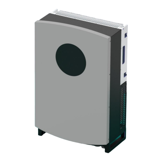
4. Product Description 4. Product Description View of the Product View of the HY3 Series Hybrid Inverter Symbols on the Label Symbol Explanation CE Mark Refer to User Manual Caution, Risk of Danger Caution, Risk of Electric Shock Caution, Hot Surface User Manual MANUAL-HY3-EN-V1.00... -
Page 9: System Diagram
4. Product Description System Diagram The HY3 Series hybrid inverter can be used with battery and solar array to form a solar-storage system. It can improve the self-consumption of solar energy, and can also perform as a backup power supply. -
Page 10: Operating Mode Introduction
4. Product Description Operating Mode Introduction Several Common Operation Modes Mode 1 In the daytime when there is sufficient sunlight, the solar energy supports the loads first; excess energy is stored in battery; rest energy is fed into grid (or limited if required). -
Page 11: Mounting
5. Mounting 5. Mounting Selecting the Mounting Location NOTICE Check to make sure the installation location does not fall into any of the following conditions. If any do, then a risk assessment will be required. Check List Unsafe due to assessment of occupational health safety risks. ... - Page 12 5. Mounting Requirements of Mounting Enough space around inverter is suggested, as left ≥300mm picture shows. ≥200mm ≥200mm ≥300mm ≥500mm Max 15° The inverter must be mounted in upright position with a tilt angle no more than 15 degree. User Manual MANUAL-HY3-EN-V1.00...
-
Page 13: Mounting The Inverter
5. Mounting Mounting the Inverter Procedure Step 1 Please mounting bracket as a template to drill 6 holes on the wall (10mm in diameter, and 80mm in depth). expansion bolts accessory box, mounting bracket onto the wall tightly. Step 2 Lift the inverter with the handles ... -
Page 14: Electrical Connection
6. Electrical Connection 6. Electrical Connection Overview of Connection Area BAT1+ BAT2+ GRID BAT1- BAT2 - WIFI Position Designation Solar Switch Additional Grounding Point Solar Input Ports Battery Input Ports WiFi Module Port Communication Port (Include DRM, smart meter port, 2 BMS ports, 2 CAN ports) Grid Connector EPS Connector User Manual... -
Page 15: Wiring Diagram
6. Electrical Connection Wiring Diagram A. Diagram for Australia and New Zealand NOTICE For Australian safety countries, the neutral line of EPS port must NOT be isolated or switched. HY3 Series Solar Array Hybrid Inverter Battery A B C N... - Page 16 6. Electrical Connection B. Diagram for Other Countries NOTICE For other countries, the neutral line of EPS port can be isolated or switched. HY3 Series Solar Array Hybrid Inverter Battery A B C N Grid A B C N Port...
-
Page 17: Pv Connection
panel frames. The HY3 Series inverters are designed with 2 MPPT trackers and the HY3-8000HV/10000HV have 3 PV inputs. Only one solar string is permitted for one input port. If the inputs of the PV panels are paralleled;... -
Page 18: Grid Connection
6. Electrical Connection Grid Connection Before connecting, make sure: Use the Grid Connector from the accessory box. The grid voltage and frequency is in the permissible range. External AC breaker must be used for cutting off the inverter from grid when necessary. ... -
Page 19: Eps Connection
6. Electrical Connection EPS Connection If you want to use the energy storage system to power the house (as a standalone system or during Grid failure), the EPS connector should be used and the EPS function should be enabled. Otherwise one can leave the EPS port un-connected. -
Page 20: Battery Connection
Before connecting, make sure: Use the Battery Connectors from the accessory box. The battery is compatible with HY3 Series. Please contact local distributor or manufacturer for approved battery list. A DC breaker with OCP function is compulsory to be installed between inverter and battery. The battery ... - Page 21 6. Electrical Connection Step 3 Connect the wires from inverter to a DC breaker firstly, and then connect BAT1+ BAT2+ G R I D the battery and DC breaker with a O FF BAT1- BAT2 - cable of 10-16mm core section.
-
Page 22: Smart Meter Connection
6. Electrical Connection Smart Meter Connection NOTICE The inverter needs the data from the smart meter, to monitor the power usage in the house, and control the generation/charge/discharge process according to smart meter’s data. The smart meter communication only works when it is compatible with the inverter. Please use the provided meter from the accessory box. -
Page 23: Wifi Module Connection
Configure network WiFi module by Hoymiles APP , which will be introduced in Chapter 7.4. DRM Connection DRM is provided to support several demand response modes by certain control signals. If it is not required, one can leave it un-connected. -
Page 24: Operating The Inverter
7. Operating the Inverter 7. Operating the Inverter Explanation of LED Indicators The LEDs on the screen indicate the operating state. 1. Battery SOC 2. Solar Power 3. Status 6. Communication Indicator Indicator 4. Fault 5. WiFi Status Indicator Indicator Explanation of LED Indicators 1. -
Page 25: Commission
Step 4 Switch on the loads Make sure all the loads are ready to be powered on. Step 5 Configure network for Configure WiFi module via Hoymiles APP for remote monitoring. WiFi module User Manual MANUAL-HY3-EN-V1.00... -
Page 26: Decommission
7. Operating the Inverter Decommission Procedure Step 1 Turn off the loads. Step 2 Turn off the PV. Step 3 Turn off the battery. Step 4 Turn off the grid. Step 5 Wait for at least 5 minutes after the LED indicators black out for the internal circuits to discharges energy. -
Page 27: Wifi Configuration
Get WiFi Module Ready Press the button on the WiFi module three (3) times, and wait for about 30 seconds. Step 2 Connect to WiFi Module Login Hoymiles APP . Connect to WiFi module’s network as following. Step 3 Configure Network Configure network for WiFi module with wireless network or wired network. -
Page 28: App Monitoring
Hoymiles APP is an external monitoring and configuration application for Hoymiles inverters. One can monitor, operate, set, and update the inverter through the APP . Search “Hoymiles” in the iOS Store and Google Play, to download the APP and get started. T ES T... -
Page 29: Troubleshooting
8. Troubleshooting 8. Troubleshooting To be released. User Manual MANUAL-HY3-EN-V1.00... -
Page 30: Technical Datasheet
9. Technical Datasheet 9. Technical Datasheet Models HY3-5000HV HY3-6000HV HY3-8000HV HY3-10000HV INPUT (DC) Max. recommended DC power [W] 6000 8000 10000 13000 Max. DC voltage [V] 1000 1000 1000 1000 Nominal DC operating voltage [V] Max. input current [A] 11/11 11/11 11/11 11/20... - Page 31 9. Technical Datasheet EFFICIENCY MPPT efficiency [%] 99.9 Euro efficiency [%] Max. efficiency [%] 97.8 Battery charge/discharge efficiency [%] 97.8 (PV-BAT) 96.0 (BAT-AC) POWER CONSUMPTION Standby consumption(night) [W] <7 Idle mode STANDARD Safety IEC62109-1-2 / IEC62040/ AS3100 EN61000-6-1/EN61000-6-2/EN61000-6-3 Certifications VDE0126-1-1, A1:2012/VDE-AR-N4105/G59-3/AS4777/EN50438/CEI 0-21/IEC62040/IEC62619/ISO13849-2/SN29500/IEC615086 ENVIRONMENT LIMIT Protection class...
-
Page 32: Warranty Card
Warranty Card Warranty Card ITEM DESCRIPTION REMARK Customer Name Address Product Model Product Serial Number Date of Installation Installer Description of Problem User Manual MANUAL-HY3-EN-V1.00... - Page 33 NOTE PAGE...
- Page 34 NOTE PAGE...
- Page 36 Hoymiles Converter Technology Co., Ltd. Add: No.18, Kangjing Road, Hangzhou, 310015, China Tel: +86 571 2805 6101 Email: service@hoymiles.com www.hoymiles.com...
Need help?
Do you have a question about the HY3 Series and is the answer not in the manual?
Questions and answers