Table of Contents
Advertisement
Quick Links
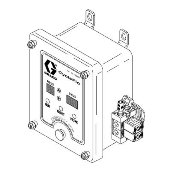
CycleFlo Pneumatic Pump Controller
Part No. 195264 (120 VAC)
Part No. 196706 (240 VAC)
'
Integrated Air Valves with Silenced Exhaust
'
32 Batch Presets
'
1-999 Pump Cycles per Batch Preset
'
x10 Cycle Multiplier for High Volume
Applications (10 – 9,990 Cycles)
'
16 Pump Cycle Rates (10 CPM to 200 CPM)
'
Easy Field Programming
'
Self-Test Function for Easy Troubleshooting
'
Standard 120 or 240 VAC Power
'
120 psi (.8 MPa, 8 bar) Maximum Air Inlet Pressure
GRACO INC
P.O. BOX 1441
MINNEAPOLIS, MN 55440-1441
COPYRIGHT 1999, GRACO INC
Graco Inc. Is registered to I.S. EN ISO 9001
309003
Rev C
Advertisement
Table of Contents

Subscribe to Our Youtube Channel
Related Manuals for Graco CycleFlo 195264


Summary of Contents for Graco CycleFlo 195264
- Page 1 Self-Test Function for Easy Troubleshooting Standard 120 or 240 VAC Power 120 psi (.8 MPa, 8 bar) Maximum Air Inlet Pressure GRACO INC P.O. BOX 1441 MINNEAPOLIS, MN 55440-1441 COPYRIGHT 1999, GRACO INC Graco Inc. Is registered to I.S. EN ISO 9001...
-
Page 2: Table Of Contents
PERATION ................................10 EMOTE PERATION TROUBLESHOOTING ................................11 SELF-TEST MODE ................................12 NOTES ..................................... 13 PARTS ..................................... 14 TYPICAL INSTALLATION DIAGRAMS..........................15 SPECIFICATIONS ................................. 18 MOUNTING INFORMATION ..............................19 GRACO STANDARD WARRANTY ............................ 20 GRACO PHONE NUMBER ..............................20 309003... -
Page 3: Warnings
Do not exceed the maximum working pressure of the lowest rated system component. • Route hoses away from traffic areas, sharp edges, moving parts, and hot surfaces. Do not expose Graco hoses to temperatures above 200 degrees F (93 degrees C) or below 0 degrees F (-18 degrees C). •... - Page 4 Fire, Explosion, and Electric Shock Hazard Improper grounding, poor air ventilation, open flames, or sparks can cause a hazardous condition and resulting fire or explosion and serious injury. • Ground the pumping equipment. • Proper grounding dissipates static electricity. • This equipment is not intended for intrinsically safe areas.
-
Page 5: General Description
¼” OD push-in tube fittings installed in the “A” and “B” ports. On pumps larger than the Husky 205, a three way solenoid valve (Graco Part Number 115605 or equivalent) should be installed on the main air supply to the pump. This ensures that pressure is not generated by the pump when the controller is not operating. -
Page 6: Electrical Connections
The 24 Volt DC Air Supply Valve Signal output is used to control a three way valve (Graco part number 115605) or equivalent) on the main air supply of pumps larger than the Husky 205. - Page 7 The AIR SUPPLY VALVE signal is a 24VDC output signal. This signal is drives the external 6W solenoid valve (Graco part number 115605) controlling the main air supply. (Required for pumps larger than the Husky 205). SOLENOID VALVE #1 and #2 signals (24VDC output signals) are pre-connected to the air valves on the right side of the CycleFlo.
-
Page 8: Setup & Programming
Setup & Programming An 8 position DIP switch (SW1) (see figure 1 for location) is used to set the cycle rate and cycles multiplier. It is also used to invoke various test modes. Before the CycleFlo can be put into operation, the following (See figure 4) parameters must be programmed for each particular application: Fig.3 –... -
Page 9: Presets
Presets The CycleFlo has 32 programmable Presets to easily switch between amounts of fluid delivered by the pump during a RUN cycle. Each preset is programmed with the number of times the pump will be cycled. Use the buttons on the front panel to step through the presets. The PRESET display will indicate the selected PRESET program number and the CYCLES display will show the associated number of pump cycles. -
Page 10: Operation
Operation Priming the Pump A priming feature allows for the temporary operation of the pump for priming purposes. The pump cycle rate during priming is controlled by the 8 position DIP switch (SW1). Pressing the PRIME button on the front panel will start the pump cycling while the button is held. Once primed, release the button to stop pump operation. -
Page 11: Troubleshooting
Troubleshooting The following is a list of possible problems and their causes. The CycleFlo also has a built-in self-test mode that allows dynamic testing of all components. Troubleshooting Guide Problem Possible Cause & Remedy No operation at all 1. Blown fuse – check fuse & replace with 250V 1/4A type 2. -
Page 12: Self-Test Mode
Self-Test Mode During this test the solenoid valves may be activated.This will activate a connected pump. To prevent inadvertent pumping, disconnect the air supply to the solenoid valves or remove the air lines to the pump. TEST MODE (SWI-7) The CycleFlo has a built-in test program that allows for dynamic testing of all internal and external components. Once activated, the self-test mode will do the following continuously until the test mode is de-activated: •... -
Page 13: Notes
Notes 309003... -
Page 14: Parts
Parts Ribbon Cable Main Board Display Board Valve Enclosure Enclosure Parts Part No. Description 195264 CycleFlo Pneumatic Pump Controller Unit (120 VAC) 196706 CycleFlo Pneumatic Pump Controller Unit (240 VAC) 115416 Enclosure 115384 Emblem (Not shown – located on front of unit) (120 VAC) 116116 Emblem (Not shown –... -
Page 15: Typical Installation Diagrams
Typical Installation Diagrams 120 or 240 VAC CycleFlo Controller Remote Run Input Compressed Air In Diaphragm Pump (Husky 205 shown) PH Controller, Flow Controller, Timer, etc. Sends on/off signal to CycleFlo Controller 9409A 309003... - Page 16 CycleFlo Controller CycleFlo Controller Chemical 120 or 240 VAC Injector Air Supply Valve Signal (24VDC) Remote Run Input Compressed Air Solenoid Solenoid Valve #2 Valve #1 Air Supply Solenoid Valve Husky 1040 Metering Pump Flow Controller sends and on/off signal to the CycleFlo Controllers Flow Sensors...
- Page 17 CycleFlo Controller Water Neutralization CycleFlo Controller Remote Run 120 or 240 Input Air Supply Valve Signal (24 VDC) Compressed Air in Solenoid Solenoid Valve #1 Valve #2 Air Supply Solenoid Valve Flow Meter Husky 1040 Remote Pump Flow Chemical Sensor Injector Sends on/off signal to CycleFlo Controller...
-
Page 18: Specifications
CycleFlo Controller Water Treatment Compressed Air In Air Supply Solenoid Valve CycleFlo Controller Air Supply Valve Signal (24 VDC) Cooling Coils 120 or 240 VAC Remote Run Input Solenoid Solenoid Valve #1 Valve #2 Husky 1040 Metering Pump PH Controller - sends on/off signal to CycleFlo Corrosion... -
Page 19: Mounting Information
Mounting Information 4” 102 mm 8 7/8” 225 mm 309003... -
Page 20: Graco Standard Warranty
Graco, Graco will, for a period of twelve months from the date of sale, repair or replace any part of the equipment determined by Graco to be defective. This warranty applies only when the equipment is installed, operated and maintained in accordance with Graco's written recommendations.
Need help?
Do you have a question about the CycleFlo 195264 and is the answer not in the manual?
Questions and answers