Graco Dispensit 1093 Operation & Maintenance Manual
Hide thumbs
Also See for Dispensit 1093:
- Setup & operation (42 pages) ,
- Operation & maintenance manual (30 pages)
Table of Contents
Advertisement
Quick Links
Operation - Maintenance
Dispensit 1093
2000 psi (14 MPa, 138 bar) Maximum Outlet Fluid Working Pressure
Metal Sleeves: 1200 psi (8 MPa, 83 bar) Maximum Material Inlet Pressure
Plastic Sleeves: 400 psi (2.8 MPa, 28 bar) Maximum Material Inlet Pressure
100 psi (0.7 MPa, 7 bar) Maximum Air Working Pressure
110°F (43°C) Maximum Ambient Temperature
150°F (65°C) Maximum Operating Temperature
Important Safety Instructions
Read all warnings and instructions in this manual.
Save these instructions.
313566D
EN
Advertisement
Table of Contents

Related Manuals for Graco Dispensit 1093


Summary of Contents for Graco Dispensit 1093
- Page 1 Operation - Maintenance Dispensit 1093 313566D 2000 psi (14 MPa, 138 bar) Maximum Outlet Fluid Working Pressure Metal Sleeves: 1200 psi (8 MPa, 83 bar) Maximum Material Inlet Pressure Plastic Sleeves: 400 psi (2.8 MPa, 28 bar) Maximum Material Inlet Pressure 100 psi (0.7 MPa, 7 bar) Maximum Air Working Pressure...
-
Page 2: Table Of Contents
Typical Installation ..... . .13 Graco Standard Warranty ....30 Valve Mounting Diagram . -
Page 3: Warnings
Warnings Warnings The following warnings are for the setup, use, grounding, maintenance, and repair of this equipment. The exclama- tion point symbol alerts you to a general warning and the hazard symbols refer to procedure-specific risks. When these symbols appear in the body of this manual or on warning labels, refer back to these Warnings. Product-specific hazard symbols and warnings not covered in this section may appear throughout the body of this manual where applicable. - Page 4 Warnings WARNING FIRE AND EXPLOSION HAZARD Flammable fumes, such as solvent and paint fumes, in work area can ignite or explode. Paint or solvent flowing through the equipment can cause static sparking. To help prevent fire and explosion: • Use equipment only in well ventilated area. •...
- Page 5 Warnings WARNING MOVING PARTS HAZARD Moving parts can pinch, cut or amputate fingers and other body parts. • Keep clear of moving parts. • Do not operate equipment with protective guards or covers removed. • Pressurized equipment can start without warning. Before checking, moving, or servicing equipment, follow the Pressure Relief Procedure and disconnect all power sources.
-
Page 6: Important Isocyanate (Iso) Information
Important Isocyanate (ISO) Information Important Isocyanate (ISO) Information Isocyanate Conditions Keep Components A and B Separate Spraying or dispensing fluids that contain isocyanates creates potentially harmful mists, vapors, and Cross-contamination can result in cured material in atomized particulates. fluid lines which could cause serious injury or damage •... -
Page 7: Changing Materials
Important Isocyanate (ISO) Information Foam Resins with 245 fa Blowing Agents Some foam blowing agents will froth at temperatures above 90°F (33°C) when not under pressure, especially if agitated. To reduce frothing, minimize preheating in a circulation system. Changing Materials NOTICE Changing the material types used in your equipment requires special attention to avoid equipment damage... -
Page 8: Grounding
Important Isocyanate (ISO) Information Installation Grounding Cycle Detection Spool Sensors The spool sensors are magnetic reed switches and must be connected to an electrical control. An LED on the switch illuminates to indicate the shifting of the spool. The equipment must be grounded to reduce the risk of static sparking and electric shock. -
Page 9: Component Identification
Component Identification Component Identification Typical System Configurations Valve Controls CONTROL POWER System shown with optional controls 313566D... -
Page 10: Typical Feed System Components
Component Identification Typical Feed System Components 5 Gallon Pail Cover 5 Gallon Pail Cover with Diaphragm with Diaphragm Pump Pump and Agitator 20 oz Cartridge Feed with Mounting Post 1 Gallon Ram and Pump WARNING DO NOT SERVICE WITHOUT REMOVING AIR PRESSURE AND WEARING SAFETY GLASSES. -
Page 11: Typical Feed System Components (Continued)
Component Identification Typical Feed System Components (continued) 5 Gallon Tank with Diaphragm Pump and Stand 5 Gallon Tank with 5:1 Pump and Stand 10 Gallon Tank with Diaphragm Pump, Agitator, 10 Gallon Tank with 5:1 Pump, Agitator, Vacuum, Vacuum, and Stand and Stand 313566D... -
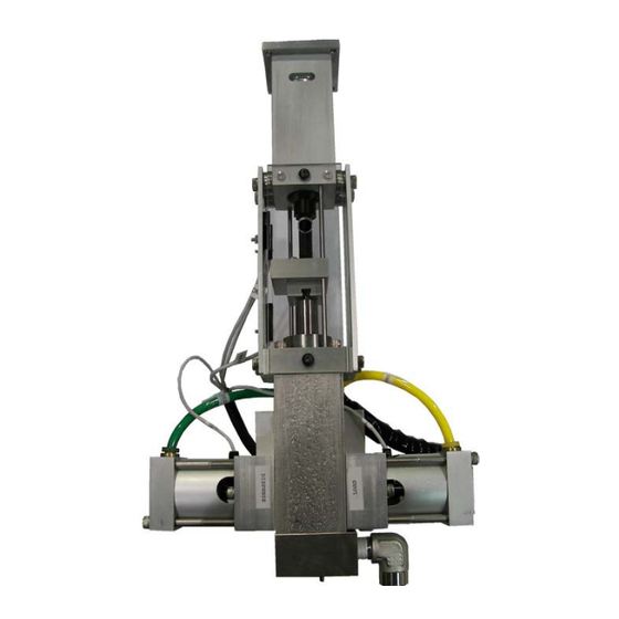
Page 12: Model 1093 Main Component Illustration
Component Identification Model 1093 Main Component Illustration 313566D... -
Page 13: Setup
Air Controller: The Model 1093 requires a programmable servo or stepper motor controller. Both are offered by Graco, or they can be supplied by the customer. Inside diameter of standard motor coupler is .25”. Air Lines: Install pneumatic supply lines for spool shifting between fill and dispense cycles. -
Page 14: Valve Mounting Diagram
Setup Valve Mounting Diagram Motor Mounting Diagram If using a non-Graco motor with the dispense valve, use the following diagram to install the non-Graco motor onto the valve. See Motor Specifications on page 29. 2.22 2.039 0.182 0.182 Ø 0.251 STANDARD 2.039... -
Page 15: Operation
Operation Operation The operation of the 1093 metering valve is controlled Step 2: Shift by an external source. If a Control Box was purchased, see the Control Box manual for operation instructions. See Related Manuals on page 2. Sequence of Operation Step 1: Reload •... -
Page 16: Operating Procedures
Operation Operating Procedures 6. Increase the material inlet pressure for loading. Recommended Material Supply Pressure A Dry Run demonstrates the valve's controls and dispensing steps. It also verifies that the valve is work- Minimum - 20 psi (1.4 bar) ing correctly before you load materials. For Plastic Spools Maximum - 400 psi (27.6 bar) For Steel Spools Maximum - 1200 psi (82.7 bar) Dry Run:... -
Page 17: Pressure Relief Procedure
4. Dispense 5 shots. Shots should be at least 75% of the full stroke. 5. Extend the metering rod into the tubes. If Graco controls are provided with the system, see the Controls manual. See Related Manuals on page 2. -
Page 18: Maintenance
Maintenance Maintenance Perform the following procedures once a shift. 2. Remove mounting screws to remove valve from its support. NOTE: If material is leaking, see Troubleshooting on 3. On the right side of the valve, remove Valve End page 26. Cap (9). - Page 19 Maintenance Disassembly of Motor Coupling Section Refer to the illustration on page 14 and the drawings in the back of thi smanual for your exact model. 17. Remove Screws (7) to disconnect Connection Block (6) from Lead Screw Connector Block. 18.
-
Page 20: 1093 Valve
Maintenance 1093 Valve 313566D... -
Page 21: 1093 Valve Shared Components
Maintenance 1093 Valve Shared Components Part Description A2A05400 KIT, 1093, drive assy, stepper 95/0866/00 O-RING, vit A2010209 VALVE, 1093, main blk, ss, 2 in, etc 96/0509/98 SCREW, shc 16D002 CAP, end, air cyl, spl 95/0504/01 O-RING, buna 95/0601/01 SEAL, u-cp A2000009-1 PISTON, 1093, spool 01/2801-1/97... - Page 22 Maintenance NOTE: Use caution as you install new U-cup and Before proceeding, remove any old o-rings or seals from Posipak seals so that they are not pinched or torn. Do the valve and discard, clean the valve parts with an this by making sure they are lubricated, and by tucking appropriate solvent and replace o-rings and seals with the lips of the seal inward before uniformly pushing them...
- Page 23 Maintenance Install the Spool Wet Seal Retainer on the Main 14. Slide the key slot in the Connection Block (37) over Body the end of the Metering Rod (2). 3. Install a lubricated O-ring (20) on the left side of the 15.
- Page 24 Maintenance 25. Install the Needle Block (31) with Screws. Remount Mounting Plate using Socket Head Cap Screws the valve. Install the home and spool sensors being (17). careful not to overtighten the set screws. Install the air supply lines and connect the power. Perform the Dry Run, Loading &...
-
Page 25: Motor And Motor Coupling Illustration
Motor and Motor Coupling Illustration Motor and Motor Coupling Illustration Fig. 1: Pin Alignment Illust. DESCRIPTION 1093,RETAINER,OIL CUP,SMALL 1093,RETAINER,OIL CUP,LARGE PLATE,TIE,RIGHT,PD,1.5B PLATE,TIE,LEFT,PD44,3SLOT> SCREW,SHC,10-24X1.00,MS,E@@ ROD,GUIDE,1093,1.5BX2.0S 1093,CONNECTOR BLK,METERING SCREW,SHC,8-32X0.63,SS> 1093,CONNECTOR BLK,LEAD SCR SCREW,FHSC,10-32X0.50,MS,E@ SCREW,SHC,SHLDR,1/4X.50,10- HOUSING,LEADSCREW,STPR/SRVO SCREW,BHCS,8-32X0.31,MS,E@@ RING,RET,EXT,0.625,MS> BEARING,BALL,.625IDX1.375OD NUT,LEADSCREW,DRIVE,STPR/SR LEADSCREW,DRIVE,1093 SCREW,SHC,10-32X0.50,MS,E@@ COUPLER,LDSCREW,PD3,1/4 MTR SCREW,SHC,6-32X0.38,MS@@@ RETAINER,BEARING,LEADSCREW, PLATE,MTG,STPR,PD44,REM... -
Page 26: Troubleshooting
Troubleshooting Troubleshooting Perform Pressure Relief Procedure before perform- ing any troubleshooting procedure. Problem Cause Solution Metering valve stalling and no mate- Blocked needle Check needle for cured material, rial being dispensed despite ade- replace as required quate input pressure Metering valve not discharging nor- Low material level in reservoirs Fill material reservoirs and prime the mal or full volume... -
Page 27: Model 1093 Recommended Spare Parts
Model 1093 Recommended Spare Parts Model 1093 Recommended Spare Parts NOTE: These parts are routine supply items or wear parts not covered by warranty for normal wear. Quantity Description Part Number SEAL KIT, 1093 see assembly drawing for part number DISPENSE SLEEVE see assembly drawing for part number METERING ROD... -
Page 28: General Guidelines For O-Rings And U-Cup Seals
General Guidelines for O-Rings and U-Cup Seals Sizes and materials of construction for O-rings and U-cup seals are selected by Graco based on compatibility with the chemicals to which they will be exposed. Solvents that may remove residual chemicals often have negative effects on the mechanical properties of O-rings and seals. -
Page 29: Technical Data
........ -
Page 30: Graco Standard Warranty
With the exception of any special, extended, or limited warranty published by Graco, Graco will, for a period of twelve months from the date of sale, repair or replace any part of the equipment determined by Graco to be defective.
Need help?
Do you have a question about the Dispensit 1093 and is the answer not in the manual?
Questions and answers