Table of Contents
Advertisement
Quick Links
Advertisement
Table of Contents

Subscribe to Our Youtube Channel
Related Manuals for Wood-mizer TVS Series


Summary of Contents for Wood-mizer TVS Series
- Page 3 Twin Vertical Saw Safety, Operation, Maintenance & Parts Manual TVSE11S rev. A9.01 TVSE15S rev.A9.01 Safety is our #1 concern! Read and understand all safety information and instructions before operating, setting up or maintaining this machine. Form #1001 This is the original language for the manual...
-
Page 4: Table Of Contents
Table of Contents Section-Page SECTION 1 SAFETY Safety Symbols..................1-1 Safety Instructions ..................1-2 Observe Safety Instructions Wear Safety Clothing Keep the Machine And Area Around Clean Dispose Of Sawing By-Products Properly Check the Machine Before Operation Keep Persons Away Keep Hands Away Use Proper Maintenance Procedures Keep Safety Labels In Good Condition FIRE-FIGHTING... - Page 5 Table of Contents Section-Page Miscellaneous Lubrication ..............5-3 Belts......................5-4 Drive Belt Adjustment................5-4 Feed Track Chain Tension..............5-7 Log Deck and Transfer Deck Drive Chain Tension......5-10 Lube Mizer System................5-11 5.10 Safety Devices Inspection ..............5-12 SECTION 6 ALIGNMENT Routine Alignment Procedure ..............6-1 Blade Installation And Tracking Blade Wheel Alignment Aligning the Blade Guides See Section...
-
Page 6: Safety
SAFETY Safety Symbols SECTION 1 SAFETY Safety Symbols The following symbols and signal words call your attention to instructions concerning your personal safety. Be sure to observe and follow these instructions. DANGER! indicates an imminently hazardous situation which, if not avoided, will result in death or serious injury. -
Page 7: Safety Instructions
It is always the owner's responsibility to comply with all applicable national and local laws, rules and regulations regarding the ownership and operation of your Wood-Mizer TVS/SVS saw. All Wood-Mizer TVS/SVS owners are encouraged to become thoroughly familiar with these applicable laws and comply with them fully while using the machine. -
Page 8: Wear Safety Clothing
SAFETY Wear Safety Clothing Wear Safety Clothing WARNING! Secure all loose clothing and jewelry before operating the machine. Failure to do so may result in serious injury or death. WARNING! Always wear gloves and eye protection when handling bandsaw blades. Changing blades is safest when done by one person! Keep all other persons away from area when coiling, carrying or changing a blade. -
Page 9: Check The Machine Before Operation
SAFETY Check the Machine Before Operation Check the Machine Before Operation DANGER! Make sure all guards and covers are in place and secured before operating the machine. Failure to do so may result in serious injury. WARNING! Fasten the machine to the floor before operating. IMPORTANT! The machine’s operator should get training in operation and adjustment of the machine. -
Page 10: Keep Hands Away
SAFETY Keep Hands Away Keep Hands Away DANGER! Always shut off the blade motor before changing the blade. Failure to do so will result in serious injury. DANGER! Motor components can become very hot during operation. Avoid contact with any part of a hot motor. Contact with hot motor components can cause serious burns. - Page 11 SAFETY DANGER! Hazardous voltage inside the electric boxes and at the motor can cause shock, burns, or death. Disconnect and lock out power supply before servicing! Keep all electrical component covers closed and securely fastened during machine operation. WARNING! Consider all electrical circuits energized and dangerous. WARNING! Disconnect and lock out power supply before servicing! Failure to do so may result in serious injury.
-
Page 12: Keep Safety Labels In Good Condition
SAFETY Keep Safety Labels In Good Condition Keep Safety Labels In Good Condition IMPORTANT! Always be sure that all safety decals are clean and readable. Replace all damaged safety decals to prevent personal injury or damage to the equipment. Contact your local distributor, or call your Customer Service Representative to order more decals. - Page 13 SAFETY Safety Labels Description TABLE 1-1 099219 Blade tension adjustment. Turn right to tighten; turn left to release. 099219 099221 Keep all persons at a safe distance from work area when operating the machine. 099221 096314 Keep all persons at a safe distance from work area when operating the machine.
- Page 14 SAFETY Safety Labels Description TABLE 1-1 096316 Opening of the electric box is possible only when the switch is in the ”0” position. 096319 Always disconnect the power cord before opening the electric box. 098177 Always disconnect the power cord before performing any service.
- Page 15 SAFETY Safety Labels Description TABLE 1-1 099540 CAUTION! Gear train - Keep a safe distance! 099540 101176 CAUTION! Compressed air in the system even after electric power disconnection. 101176 096321 Blade movement direction 500031 CAUTION! Do not adjust the turnbuckles! Safety MHdoc031723 1-10...
- Page 16 SAFETY Safety Labels Description TABLE 1-1 S12004G Always wear eye protection equipment when operating this machine. S12005G Always wear ear protection equipment when operating this machine. 501465 CAUTION! Always wear safety boots when operating this machine. 501467 Lubrication point P11789 Blade alignment.
- Page 17 SAFETY Safety Labels Description TABLE 1-1 092597 Blade tension adjustment (See Section 2.5) 092597 P85070 CE sign S20097 Motor rotation direction S20097 099504 Visible and/or invisible laser radiation. Avoid eye or skin exposure to direct or scattered radiation. 099504 505346 Tensioner Valve Handle Placement, TVS TVS 505346 505347...
-
Page 18: Operation
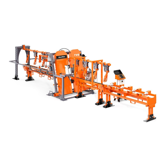
General Information Thank you for choosing Wood-Mizer wood processing equipment! Wood-Mizer is committed to providing you with the latest technology, best quality and strongest customer service available on the market today. We continually evaluate our customers’ needs to ensure we’re meeting current wood-processing demands. Your comments and suggestions are welcome. - Page 19 OPERATION General Information See Figure 2-1. The TVS main components are shown below. Outfeed Table Saw Heads Infeed Table Electric Box Operator’s Box FIG. 2-1 TVS MAIN COMPONENTS Operation MHdoc031723...
-
Page 20: Control Overview
OPERATION Control Overview Control Overview 1. Control Panel See Figure 2-2. The control panel includes switches to start and stop the feed track and the saw heads. Real Size (mm) Check real size START TBS 01 Setworks Position Size (mm) STOP SAVE ABCDE... - Page 21 OPERATION Control Overview to increase the speed, turn left to reduce the speed. 5. Key Switch The key switch has three positions: “0” position - all electrical circuits are off, position - all electrical circuits are on, position - releases the motors disk brake, it is possible to run the track feed motor but it is not ...
-
Page 22: Tvs Setup
OPERATION TVS Setup TVS Setup IMPORTANT! Before starting to use the machine you have to meet the following conditions: Set up the machine on firm and level ground. The machine can be operated with the sawdust collection system only. ... - Page 23 OPERATION TVS Setup IMPORTANT! When starting the machine for the first time, check that blade rotation direction is as indicated by the arrow located on the blades covers. If the rotation direction is incorrect, invert the phases in the phase inverter located in the power socket (electric box). Setting the phases in the phase inverter correctly will ensure correct rotation directions of all machine motors (machines not equipped with phase failure relay).
- Page 24 OPERATION TVS Setup picture below. FIG. 2-2 MHdoc031723 Operation...
-
Page 25: Replacing The Blades
OPERATION Replacing The Blades Replacing The Blades DANGER! Always shut off the machine motors before changing the blades. Failure to do so may result in serious injury. WARNING! Always wear gloves and eye protection whenever handling bandsaw blades. Changing blades is safest when done by one person! Keep all other persons away from work area when changing blades. -
Page 26: Tensioning The Blades
OPERATION Tensioning The Blades Next, tension the blade as described in the following instructions. NOTE: Before installing the blade on the left (when facing the operator box) saw head, invert the blade (See Section 4.3 Inverting The Blade in “Blade Handbook”). -
Page 27: Tracking The Blade
OPERATION Tracking The Blade position. CAUTION! Always release the blade tension when the machine is not in use. Tracking The Blade 1. Open the blade housing cover of each saw head. 2. Turn the key switch to the ”H” position. 3. -
Page 28: Machine Start
OPERATION Machine Start 7. Close the blade housing cover. CAUTION! Make sure all guards and covers are in place and secured before operating or towing the machine. Failure to do so may result in serious injury. Be sure the blade housing cover is in place and secured. NOTE: After aligning the blade on the wheels, always check the blade guide spacing and location. - Page 29 OPERATION Machine Start See Figure 2-5. Start the blade motors. To do this, turn the key switch to the position and then push the Blade START button on the control panel (see the figure below). The motors should start and the blades should start spinning.
- Page 30 OPERATION Machine Start under Track Start switch. Real Size (mm) Check real size START TBS 01 Setworks Position Size (mm) STOP SAVE ABCDE START STOP STOP AUTO ENTER CAL. REAL SIZE FIG. 2-6 The feed track can be stopped by pressing one of the emergency stop buttons. The emergency stop will also stop the blade motor.
- Page 31 OPERATION Machine Start minute. Real Size (mm) Check real size START TBS 01 Setworks Position Size (mm) STOP SAVE ABCDE START STOP STOP AUTO ENTER CAL. REAL SIZE FIG. 2-7 Turn the switch clockwise to increase the feed rate, counterclockwise to slow the feed rate down. Factors that will determine what feed rate you can use include: Log diameter.
-
Page 32: Cutting Width Setting
OPERATION Cutting Width Setting Cutting Width Setting 1. Install a blade if needed and check for correct blade tension. (Section 2.5 Tensioning The Blades.) 2. Set the saw heads at the desired width using the handle and width scale shown in the figure below. See Figure 2-8. -
Page 33: Lube Additives
LubeMizer system may result. Lube Additives For further benefits, add one 12oz. (0.35 L) bottle of Wood-Mizer Lube Additive to a 5 gallon (18.9 L) jug of water. Wood-Mizer Lube Additive enables some previously impossible timbers to be cut by significantly reducing resin buildup on the blade. - Page 34 OPERATION Lube Additives See Table 2-1. Use windshield washer fluid as an antifreeze to prevent the water from freezing and damaging the LubeMizer system. See the chart below for recommended mixture levels depending on the temperature where you are sawing or storing the machine. Run the LubeMizer system on the “Continuous”...
-
Page 35: 2.10 Operation Procedure
OPERATION Operation Procedure 2.10 Operation Procedure 1. Install a blade if necessary. WARNING! Always wear gloves and eye protection when handling bandsaw blades. Changing blades is safest when done by one person! Keep all other persons away from area when coiling, carrying or changing a blade. - Page 36 OPERATION Operation Procedure does not engage rotating members resulting in possible injury. 12. Shut off the blades and feed track. Measure the finished material and adjust the saw heads in or out as necessary. Repeat with the test material until the desired finished dimension is obtained. 13.
-
Page 37: 2.11 Loading Ramp Operation
OPERATION Loading Ramp Operation 2.11 Loading Ramp Operation Use the switch located on the operator panel to turn on/off the log ramp. CAUTION! Minimum log lenght which can be handle by the loading ramp is 700mm (27,56”). Log must be placed so, that the limit switch would be activated when the log will reach the end of the ramp. -
Page 38: 2.12 Cross Transfer Deck Operation
OPERATION Cross Transfer Deck Operation 2.12 Cross Transfer Deck Operation Use the START/STOP button located on the electric box to turn on/off the transfer deck. If there is any danger to persons or equipment, press the emergency button. It will stop the transfer deck and TVS resaw. -
Page 39: Setworks Operation (Optional Equipment)
SETWORKS OPERATION (Optional Equipment) TVS Controller Panel SECTION 3 SETWORKS OPERATION (OPTIONAL EQUIPMENT) TVS Controller Panel See Pic. 3-1. Real Size (mm) Indicates Real Blades Check real size Width that the real saw heads distance should be Set Blades checked Width TBS 01 Setworks Position Size (mm) - Page 40 SETWORKS OPERATION (Optional Equipment) TVS Controller Panel Descriptions of the control panel buttons: A, B, C, D, E - Heads width memory buttons. SET ABCDE - Sets the blades width value to each memory button. ABCDE Save - Saves parameters determined by the operator. SAVE Blades width manual setting buttons (in/out).
-
Page 41: Start-Up Settings Of The Controller
SETWORKS OPERATION (Optional Equipment) Start-up Settings of the Controller Start-up Settings of the Controller 1. Setting the input divider (entered only once, at the first start-up) Turn the main switch to the ON position. Turn the key switch to position. - Page 42 SETWORKS OPERATION (Optional Equipment) Start-up Settings of the Controller 2. Auto-calibration This function should also be used in case of: replacement of the screw of blades width setting system, the motor or after lubrication of the screws and other moving elements of the heads or when significant cutting variances are observed;...
-
Page 43: Operation, Memory Buttons (A, B, C, D, E)
SETWORKS OPERATION (Optional Equipment) Operation, Memory Buttons (A, B, C, D, E) Confirm by pressing ENTER The end of the function is signalled, ”End CALL” appears and the normal mode of operation is restored. NOTE: If, during the movement, the limit switch is activated, set different head width and repeat the auto-correction function. - Page 44 SETWORKS OPERATION (Optional Equipment) Operation, Memory Buttons (A, B, C, D, E) See Pic. 3-4. Real Size (mm) Check real size TBS 01 Setworks Position Size (mm) SAVE ABCDE AUTO ENTER CAL. REAL SIZE PIC. 3-4 To use the stored value, press the required memory button and confirm by pressing ...
-
Page 45: Troubleshooting
Troubleshooting Setworks Malfunction SECTION 4 TROUBLESHOOTING Setworks Malfunction PROBLEM CAUSE SOLUTION Setworks does not work. Magnet sensor improperly Adjust the magnet sensor as adjusted shown on Photo 4-1 and Fig. 4-2. Calibrate the controller. Section Auto-calibration. The controller calcutates Improper input parameters - Check the input divider (See dimensions of boards... - Page 46 Troubleshooting Setworks Malfunction Sensor Adjustment Bolts (4) PHOTO 4-1 TVS_SWdoc031723 Troubleshooting...
- Page 47 Troubleshooting Setworks Malfunction Sensor Magnetic Strip .1-2 mm Distance between the magnet sensor and the magnetic strip 1 deg. 3 deg. Maximum sensor’s deviation from the vertical axis 3 deg. Maximum sensor’s deviation from the horizontal axis FIG. 4-2 Troubleshooting TVS_SWdoc031723...
- Page 48 Troubleshooting Setworks Malfunction PHOTO 4-3 PHOTO 4-4 TVS_SWdoc031723 Troubleshooting...
- Page 49 Troubleshooting Setworks Malfunction PHOTO 4-5 Troubleshooting TVS_SWdoc031723...
-
Page 50: Maintenance
MAINTENANCE Wear Life SECTION 5 MAINTENANCE This section lists the maintenance procedures that need to be performed. This symbol identifies the interval (hours of operation) at which each maintenance procedure should be performed. Be sure to refer to the motor manual for maintenance procedures concerning the blade motor. Wear Life See Table 5-1. - Page 51 MAINTENANCE Sawdust Removal See Figure 5-1. FIG. 5-2 CAUTION! Never use grease on the saw heads lower rollers as it will collect sawdust. 2. Remove the excess sawdust and slabs from the infeed and outfeed table, log deck and cross transfer deck.
-
Page 52: Miscellaneous Lubrication
MAINTENANCE Miscellaneous Lubrication Miscellaneous Lubrication 1. Apply a thin film of a lithium grease to the saw heads width adjustment screw to help prevent it from rusting. 2. Using the grease nipples, lubricate the chain drive shaft bearings, hold down roller bearing of the infeed table, saw heads width adjustment screw bearing with a lithium grease. -
Page 53: Belts
MAINTENANCE Belts See Figure 5-5. CROSS TRANSFER CROSS TRANSFER LOG DECK LOG DECK DECK DECK FIG. 5-6 4. Make sure all safety warning decals are readable. Remove sawdust and dirt. Replace any damaged or unreadable decals immediately. Order decals from your Customer Service Representative. Belts 1. - Page 54 MAINTENANCE Drive Belt Adjustment FIG. 5-7 To adjust the drive belt tension: 1. Loosen the four motor mounting bolts (see Figure 3-3). 2. Loosen the lock nuts on the adjustment bolts. Using the adjustment bolts move the motor mounting plate down to tension the drive belt, move the motor plate up to loosen the belt. Next tighten the lock nuts.
- Page 55 MAINTENANCE Drive Belt Adjustment 3. Tighten the four motor mounting bolts. Adjustment Bolts Adjustment Bolts Mounting Bolts FIG. 5-8 Periodically check the belt for wear. Replace if damaged or worn. See Figure 5-9. Keep the motor and drive pulleys aligned to prevent premature belt wear. To align the motor pulley to the drive pulley, loosen the mounting bolts on the motor plate and slide the motor plate in or out until it is in line with the drive pulley.
-
Page 56: Feed Track Chain Tension
MAINTENANCE Feed Track Chain Tension drive belt tension has not been changed. Mounting Bolts FIG. 5-10 Feed Track Chain Tension See Figure 5-11. If necessary, use the adjustment bolts shown below to adjust the feed track chain tension. The chain should lay freely on the upper and lower bars. CAUTION! Do not over-tension the TVS tables, Log Deck and Transfer Table chains. - Page 57 MAINTENANCE Feed Track Chain Tension See Figure 5-12. Infeed table chain tension adjustments. The bolts must be adjusted evenly. Adjustment Bolts FIG. 5-13 MAINTENANCE 25doc031723...
- Page 58 MAINTENANCE Feed Track Chain Tension See Figure 5-14. Incline Log Deck chain tension adjustments Adjustment Bolts FIG. 5-15 See Figure 5-16. Adjust Cross Transfer Deck chain tension so that the chain lay freely, on the supporting roller. Adjustment Bolts FIG. 5-17 25doc031723 MAINTENANCE...
-
Page 59: Log Deck And Transfer Deck Drive Chain Tension
MAINTENANCE Log Deck and Transfer Deck Drive Chain Tension Log Deck and Transfer Deck Drive Chain Tension Check the drive chains for tension every 40 hours of operation and tension as necessary. chains should have approximately 15mm (0,59”) of slack. See Figure 5-18. -
Page 60: Lube Mizer System
MAINTENANCE Lube Mizer System Lube Mizer System 1. Clean the lube filter as needed. To clean, Make sure the lube control is in the OFF position and the lube bottle valve is closed all the way. Unscrew the filter reservoir and flush with water. ... -
Page 61: 5.10 Safety Devices Inspection
MAINTENANCE Safety Devices Inspection 5.10 Safety Devices Inspection TVS – Safety Devices Inspection Safety devices on the TVS machine which must be checked before every shift: E-STOP circuit inspection - control box E-STOP circuit inspection - table Safety switch circuit inspection - control box arm 1 ... - Page 62 MAINTENANCE Safety Devices Inspection 2. E-STOP circuit inspection - outfeed table Turn on the blade motor; Push the E-STOP button located on the outfeed table. The blade motor should be stopped. The blade motor should not start until the E-STOP button is released. 3.
- Page 63 MAINTENANCE Safety Devices Inspection Turn on the blade motor. Stop the motor by switching the to “0” position. Measure the breaking time. Turn on the blade motor. Stop the motor by switching the to “H” position. Measure the breaking ...
-
Page 64: Alignment
Routine Alignment Procedure SECTION 6 ALIGNMENT The Wood-Mizer resaw is factory aligned. This section includes routine alignment instructions and also how to realign the resaw completely. Be scrupulous when performing all alignment steps as resaw alignment determines the accuracy of your cuts. The routine alignment procedure should be performed approximately every 1500 hours of operation. - Page 65 ALIGNMENT Blade Installation And Tracking 1. Turn the key switch to the "H" position. 2. Open the blade housing covers. 3. Manually spin one of the blade wheels until the blade positions itself on the wheels. See Figure 6-2. The blade wheels should be adjusted so that the gullet of 1 1/4" blades rides 3.0 mm (0.12") out from the front edge of the wheels (±...
-
Page 66: Blade Wheel Alignment
ALIGNMENT Blade Wheel Alignment 6.1.2 Blade Wheel Alignment The blade wheels should be adjusted so they are level in the vertical and horizontal planes. If the blade wheels are tilted vertically, the blade will want to move in the tilted direction. If the blade wheels are tilted horizontally, the blade will not track properly on the wheels. - Page 67 ALIGNMENT Blade Wheel Alignment See Figure 6-4. Alignment Bracket Rope FIG. 6-4 3. Mount the alignment brackets to the infeed and outfeed tables. Attach the rope to the lower or upper holes of the alignment bracket. Measure the distance from the rope to the infeed and outfeed tables in the places shown below.
- Page 68 ALIGNMENT Blade Wheel Alignment See Figure 6-5. A=B=C Leg Adjustment Bolts FIG. 6-5 4. Check if the ropes are aligned with the top edges of the infeed and outfeed tables. Move the appropriate table end if neccesary. See Figure 6-6. Top edges of the tables aligned with the ropes on the...
- Page 69 ALIGNMENT Blade Wheel Alignment 5. Measure the distance from the edge of the tool to the rope. The distances marked A, B, C and D must be equal. If the measurements are different, use the drive side blade wheel adjustement bolts to correct its alignment.
- Page 70 ALIGNMENT Blade Wheel Alignment rope. Horizontal Plane Adjustment Bolt Vertical Plane Adjustment Bolts FIG. 6-8 6. Attach the rope to the upper holes of the alignment bracket as shown below. Next, move the alignment tools up, at the height of the ropes. Use the idle side wheel adjustment bolts in vertical plane to correct its alignment.
- Page 71 ALIGNMENT Blade Wheel Alignment See Figure 6-9. Alignment Bracket Rope FIG. 6-9 See Figure 6-10. Loosen the lock nuts on the horizontal plane adjustment bolt. Next, use the vertical MHdoc031723...
- Page 72 ALIGNMENT Blade Wheel Alignment plane adjustment bolts to adjust the idle wheel so that the adjustment tool is parallel to the rope. Horizontal Plane Adjustment Bolt Vertical Plane Adjustment Bolts FIG. 6-10 7. Check the position of the blade on the idle-side blade wheel. See Figure 6-11.
- Page 73 ALIGNMENT Blade Wheel Alignment 150060 3.0 mm (1/8”) ± 1 mm (3/64”) 1 1/4” 1 1/4" Blade Blade FIG. 6-11 See Figure 6-12. Use the cant control adjustment to adjust the idle-side blade wheel. If the blade is too far forward on the wheel, turn the cant control counterclockwise. If it is too far back on the wheel, turn the cant control clockwise.
-
Page 74: Aligning The Blade Guides
ALIGNMENT Aligning the Blade Guides 8. Check the position of the blade on the drive-side blade wheel. The blade should be positioned on the wheel as described for the idle-side blade wheel. Adjust the drive-side blade wheel if necessary. See Figure 6-13. Use the cant control adjustment to adjust the drive-side blade wheel. If the blade is too far forward on the wheel, turn the cant control bolt clockwise. -
Page 75: Complete Alignment Procedure
See Figure 6-14. Alignment Tool Pins FIG. 6-14 1. The service tool can be ordered at Wood-Mizer (part. no. 099330) or you can make it yourself according to figure 6-15. MHdoc031723 6-12... - Page 76 ALIGNMENT Blade Wheels Alignment See Figure 6-15. Alignment Tool FIG. 6-15 All pins of the alignment tool must touch the blade wheels surface. If any of the pins does not touch the blade, use the vertical plane adjustment bolts to correct the blade wheel alignment. 6-13 MHdoc031723...
- Page 77 ALIGNMENT Blade Wheels Alignment See Figure 6-16. Use the vertical plane adjustment bolts of the drive wheels so that all the pins touch the blade wheels surface. Pins Vertical Plane Adjustment Bolts FIG. 6-16 3. Install blades and apply the proper tension - See Section 2.5.
- Page 78 ALIGNMENT Blade Wheels Alignment See Figure 6-17. The blade wheels should be adjusted so that the gullet of 1 1/4" blades rides 3.0 mm (0.12") out from the front edge of the wheels (± 1.0 mm [0.04"]). 3.0 mm ± 1 mm FIG.
- Page 79 ALIGNMENT Blade Wheels Alignment See Figure 6-18. The arrows below show which bolts should be used to tilt the wheels in the required direction. FIG. 6-18 6. Remove the blades from the blade wheels. MHdoc031723 6-16...
-
Page 80: Saw Head Tilt Adjustment
ALIGNMENT Saw Head Tilt Adjustment 6.2.2 Saw Head Tilt Adjustment The saw head blades should be perpendicular to the tables and parallel to each other. First, set one of the blades so that it is perpendicular to the table and then set the other blade in relation to the first one. - Page 81 ALIGNMENT Saw Head Tilt Adjustment 2. Measure distances between the blades at the lowest and the highest points. If the measurements are not the same, adjust the saw heads using the tilt adjustment bolts shown below. Saw Head Tilt Adjustment Bolt MHdoc031723 6-18...
- Page 82 ALIGNMENT Saw Head Tilt Adjustment 3. Use the square to check if the saw heads are perpendicular to the table. Adjust if necessary. Square TVS_093 6-19 MHdoc031723...
-
Page 83: Installation Of Tables
ALIGNMENT Installation of Tables 6.2.3 Installation of Tables 1. Mount the outfeed table. See Figure 6-19. Move out the saw heads to the maximum width. Slide the front leg of the outfeed table under the TVS frame as shown. Next, bolt the table with frame using the two M12x75 bolts and washers. - Page 84 ALIGNMENT Installation of Tables the two M12x75 bolts, washers and self-locking nuts. Mounting M10x80 Bolts (4) Self-Locking M12x75 Nut (2) Bolts (2) FIG. 6-20 3. Place the level on the outfeed and infeed tables and check if they are level. See Figure 6-21.
- Page 85 ALIGNMENT Installation of Tables table is not adjustable. Outfeed Table Level Adjustment Adjustment Bolts Bolts FIG. 6-21 4. Mount the alignment brackets to the infeed and outfeed tables. Attach the rope to the lower or upper holes of the alignment bracket. Measure the distance from the rope to the infeed and outfeed tables in the places shown below.
- Page 86 ALIGNMENT Installation of Tables See Figure 6-22. A=B=C Leg Adjustment Bolts FIG. 6-22 5. Check if the ropes are aligned with the top edges of the infeed and outfeed tables. Move the appropriate table end if necessary. See Figure 6-23. Top edges of the tables aligned with the ropes on the...
- Page 87 ALIGNMENT Installation of Tables 6. Install the blades and adjust the proper tension - See Section 2.5 7. Turn the key switch to the "H" position. 8. Using a square, check if the blades are perpendicular to the tables. If they are not, put wedges under apropriate TVS frame legs.
- Page 88 ALIGNMENT Installation of Tables 099324-1) to move both saw heads left or right. Blade Outfeed Table Infeed Table Rope Adjustment Nuts FIG. 6-25 6-25 MHdoc031723...
-
Page 89: Aligning The Blade Guides
Aligning the Blade Guides 6.2.4 Aligning the Blade Guides Each Wood-Mizer resaw has two blade guide assemblies that help the blade maintain a straight cut. The two blade guide assemblies are positioned on the cutting head to guide the blade on each side of the material being cut. -
Page 90: Blade Guide Horizontal Tilt Adjustment
ALIGNMENT Blade Guide Horizontal Tilt Adjustment See Figure 6-26. Rope Loosen jam nuts and turn screws to adjust roller up or down Blade FIG. 6-26 4. Loosen the jam nut and tighten the appropriate screw until the blade guide deflects the blade 6.0 mm. - Page 91 ALIGNMENT Blade Guide Horizontal Tilt Adjustment See Figure 6-27. Clip tools to blade FIG. 6-27 Check that the blade guide does not tilt the blade left or right. A Blade Guide Alignment Tool (LTBGAT) is provided to help you measure the vertical tilt of the blade. 2.
- Page 92 ALIGNMENT Blade Guide Horizontal Tilt Adjustment See Figure 6-28. FIG. 6-28 4. The all four distances should be equal. If the distances A and C or B and D differ, it is necessary to check the saw heads centring (See Step 9. of the blade wheels adjustment procedure).
-
Page 93: Blade Guide Spacing
ALIGNMENT Blade Guide Spacing blade guide mount blocks and repeat above steps. Adjust the horizontal tilt of this guide if necessary. NOTE: If major adjustments to blade guide tilt were made, measure the actual distance with a tape from the rope to the bottom of the blade again to ensure the correct 6.0 mm (0.24") blade guide deflection. -
Page 94: Blade Guide Vertically Tilt Adjustment
6. Use the set screws to adjust the horizontal tilt of the roller. 7. Repeat steps 3-7 for the lower blade guide roller. NOTE: Once the blade guides have been adjusted, any cutting variances are most likely caused by the blade. See the Wood-Mizer® Blade Handbook, Form #600. 6-31 MHdoc031723... -
Page 95: Blades Width Scale Adjustment
ALIGNMENT Blades Width Scale Adjustment 6.2.9 Blades Width Scale Adjustment After the entire resaw has been aligned and all adjustments made, check that the blade height scale indicates the true distance between the blades. 1. Measure the distance between the blades. See Figure 6-32. - Page 96 ALIGNMENT Blades Width Scale Adjustment CAUTION! Do not adjust the saw head turnbuckle bracket nuts. The turnbuckles are factory-set and should have a little gap between the brackets. See Figure 6-33. Turnbuckle Brackets Turnbuckle Turnbuckle FIG. 6-33 6-33 MHdoc031723...
-
Page 97: Track Chain Mounting
ALIGNMENT Track Chain Mounting 6.2.10 Track Chain Mounting Mount and tension the feed chain. 1. Loosen the chain tensioner. 2. Route the feed chain as shown on the picture below. Be sure the chain is mounted in the correct direction. 3. -
Page 98: Adjustment Of The Friction Assembly (Manual Cutting Width Setting)
ALIGNMENT Adjustment of the Friction Assembly (Manual Cutting Width Setting) 6.2.11 Adjustment of the Friction Assembly (Manual Cutting Width Setting) 1. To adjust the friction assembly pressure (A) against the setting disk shaft (B): FIG. 6-35 a) Loosen the nut (B) and tighten the nut (A) to firmer press the friction assembly against the setting disk shaft. -
Page 99: Specifications
SPECIFICATIONS Overall Dimensions SECTION 7 SPECIFICATIONS Overall Dimensions See Figure 7-1. The major dimensions of the Twin Vertical Saw are shown below (all dimensions are in millimeters). Optional Equipment See Table 7-2 78.74" FIG. 7-2 Specifications MHdoc031723... - Page 100 SPECIFICATIONS Overall Dimensions See Table 7-1. The overall dimensions of the TVS are listed in the tables below. Weights Heads - 936kg / 2063 lb TVSIV2.4I - 318kg / 701 lb TVSIV3.6I - 400kg / 882 lb TVSOV4.8 - 486kg / 1071 lb Height 2148 mm / 84.57”...
- Page 101 SPECIFICATIONS Overall Dimensions See Figure 7-3. The legs layouts with dimensions are shown below (all dimensions are in millimeters). 35.43" 102.4" 8.268" 8.268" 101.77" 19.74" 214.6" TVSE15S + TVSIV2.4M + TVSOV2.4M 2601 35.43" 8.268" 8.268" 102.4" 101.77" 19.74" 501.3 2585 6253 246.2"...
-
Page 102: Cutting Capacity
Maximum Log Width 400 mm / 11.81” TABLE 7-3 See Table 7-4. Wood-Mizer offers three types of blades to provide efficient sawing. The type of wood you saw should determine which blade you choose for optimum performance. Recommended Blade Type Motor Size... - Page 103 SPECIFICATIONS Blade Motor Specifications See Table 7-6. The noise levels of the Wood-Mizer TVS are listed below Noise Level L 89,5 dB (A) TABLE 7-6 1. The noise level measurement was taken in accordance with PN-EN ISO 3746 Standard. The noise exposure level given above concerns an 8-hour work day.
-
Page 104: Dust Extractor Specifications
SPECIFICATIONS Dust Extractor Specifications Dust Extractor Specifications See Table 7-7. Specifications of the dust extractors used on the TVS are listed below. Airflow 2400 m 7874 ft Inlet diameter 150 mm / 5,9” Motor power 2x1,5 kW Number of sacks 2 pcs Sack capacity 0.25 m... -
Page 105: Laser Information
Laser Information SECTION 8 LASER INFORMATION LP - 520L -10 Industrial hermetic focusable laser line generator with rectilinearity correction. Laser for industrial applications. Technical data: Safety Class 2M from EN 60825-1:2014; Wavelength Average Output Power 10 mW; Operating Voltage 9V - 28VDC; Operating Current <100mA;... -
Page 106: Dc Electromagnetic Brake (Ce Only), Siemens Motors
DC Electromagnetic Brake (CE Only), Siemens motors Design and Principle of Operation SECTION 9 DC ELECTROMAGNETIC BRAKE (CE ONLY), SIEMENS MOTORS 1 - Electromagnet, 2 - Armature complete with brake linings, 3 - Fan, 4 - Retaining bolt 5 - Central spring, 6 - Special washer, 7 - Set screw, 8 - Self-locking nut,... -
Page 107: Service
DC Electromagnetic Brake (CE Only), Siemens motors Service Service During normal operation and at the routine inspections verify the air gap and check if all screws are tight. In case when any symptoms of inefficient braking are observed, then use the self-locking nut (8) to re-adjust the air gap to the value corresponding to Table 1. - Page 108 EC declaration of conformity according to EC Machinery Directive 2006/42/EC, Annex II, 1.A Manufacturer, Wood-Mizer Industries sp. z o.o. Nagórna 114, 62-600 Koło; Poland Tel. +48 63 26 26 000 This declaration of conformity is issued under the sole responsibility of the manufacturer.
Need help?
Do you have a question about the TVS Series and is the answer not in the manual?
Questions and answers