Table of Contents
Advertisement
Quick Links
U1000MkII WM
U1000MKII-WM:Wall-Mounted Ultrasonic Flow Meter
U1000MKII-HM:Wall-Mounted Ultrasonic Heat Meter
User Manual
Micronics Ltd, Knaves Beech Business Centre,
Davies Way, Loudwater, High Wycombe, Bucks HP10 9QR
Telephone: +44(0)1628 810456
E-mail:
sales@micronicsltd.co.uk
www.micronicsflowmeters.com
Advertisement
Table of Contents

Related Manuals for Micronics U1000MKII-WM


Summary of Contents for Micronics U1000MKII-WM
- Page 1 U1000MkII WM U1000MKII-WM:Wall-Mounted Ultrasonic Flow Meter U1000MKII-HM:Wall-Mounted Ultrasonic Heat Meter User Manual Micronics Ltd, Knaves Beech Business Centre, Davies Way, Loudwater, High Wycombe, Bucks HP10 9QR Telephone: +44(0)1628 810456 E-mail: sales@micronicsltd.co.uk www.micronicsflowmeters.com...
- Page 2 Micronics U1000MKII WM User Manual DOCUMENT AUTHORITY Issue Originator Micronics Ltd Checked Approved Date 12/12/2022 Issue 2.0 Nov 2022 Page i...
-
Page 3: Table Of Contents
Attach the PT100 Sensors (Heat Meter versions only) ............17 2.10 Zero offset the Flow Sensors .................... 18 2.11 Normal Operation ......................18 2.11.1 U1000MkII-WM Flow Meter ..................18 2.11.2 U1000MkII-WM Heat Meter ..................19 2.12 Totals and Rollover ......................19 2.13 Troubleshooting the Flow Reading ................... - Page 4 Micronics U1000MKII WM User Manual 3.2.2 Fluid Characteristics ....................23 3.2.3 System Units ......................24 3.2.4 Instrument Configuration ................... 24 3.2.5 Separation Distance ....................25 Current Output Menu ......................25 Modbus Setup Menu ......................25 M-Bus Setup Menu ......................26 Pulse Output Menu ......................
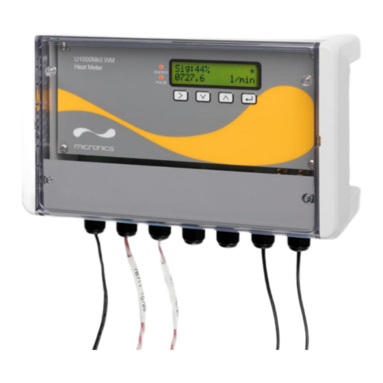
- Page 5 Figure 3: U1000MKII WM display (Heat Meter model shown) ............7 Figure 4: Location of unit ........................9 Figure 5: Typical setup of U1000MkII-WM Heat Meter for boiler applications ......... 10 Figure 6: Terminal blocks and connectors ..................11 Figure 7: U1000MKII WM Heat Meter PT100 Temperature Probe Wiring ........12 Figure 8: Fully assembled U1000MkII-WM Heat Meter unit ............
-
Page 6: Introduction
INTRODUCTION 1.1 General Description This manual describes the installation and use of the two models in the U1000MkII WM range: • U1000MkII WM Flow Meter is a wall-mounted control unit with a clamp-on ultrasonic flow sensors for measuring flow rate and total flow with a volume pulse output. It can be used as a standalone meter or as part of an integral management system. -
Page 7: How Does It Work
1.2 How Does It Work? The U1000MKII WM uses a cross correlation transit time algorithm to provide accurate flow measurements. An ultrasonic beam of a given frequency is generated by applying a repetitive voltage pulse to the transducer crystals. This transmission goes first from the downstream transducer to the upstream transducer as shown in the upper half of Figure 1. -
Page 8: Package Contents
1.3 Package Contents The unit consists of: Wall-mounted electronics and control unit Consisting of the keypad with display, power, communications, and sensor connections. Ultrasonic Flow Sensors Two transducers for flow measurement with VHB gel pads to ensure good contact with pipework. -
Page 9: Display
1.4 Display The U1000MKII WM display comprises: • One 2–line x 16-character LCD with backlight • Four tactile key switches • Two LEDs Flow Signal strength Flow Units Flow Direction Measured flow. For accurate Units applicable to * Indicates positive results, must be measured flow. -
Page 10: Quick Start Procedure
1.5 Quick Start Procedure The following procedure summarises the steps required to set up the U1000MkII WM. Please refer to the referenced sections for full details. Identify a suitable location for the sensors and guide rail on a straight length of pipe clear of bends and valves or similar obstructions (See Section Positioning). -
Page 11: Installation
INSTALLATION 2.1 Positioning For accurate measurements, the U1000MKII WM guide rail and sensors must be installed at a position where the fluid flows uniformly. Flow profile distortions can result from upstream disturbance such as bends, tees, valves, pumps, and other similar obstructions. To ensure a uniform flow profile, the unit must be mounted away from any cause of flow disturbance. -
Page 12: Additional Considerations For Locating Heat Meter Versions
For optimum reliability in chiller applications, the flow measurement needs to be made on the warmer side of the system. Figure 5: Typical setup of U1000MkII-WM Heat Meter for boiler applications Clean the Pipe’s Flow Sensor Contact Area 2.1.2... -
Page 13: Connect Power And Signal Cables
2.2.1 Power Supply The U1000MKII WM will operate within the voltage range 12–24 VDC or 24 VAC. Micronics can supply, as an optional item, a 24 VAC power supply. If you intend to use an alternative power supply, it must have a minimum rating of 7 VA per instrument. Connect the power supply to the left- hand terminal block labelled +VIN, -VIN and Screen. -
Page 14: Pulse Output Connection
Figure 7: U1000MKII WM Heat Meter PT100 Temperature Probe Wiring 2.2.4 Pulse Output Connection The isolated pulse output (labelled PULSE-A and PULSE-B) is provided by a SPNO/SPNC MOSFET relay which has a maximum load current of 500 mA and maximum load voltage of 48 VAC. The relay also provides 2500 V isolation, between the unit’s electronics and external equipment. -
Page 15: Modbus/M-Bus Connections (If Fitted)
2.2.6 Modbus/M-Bus Connections (if fitted) For detailed instructions see the separate manuals If fitted, the Modbus or M-BUS output is available at the terminal blocks labelled IO1 1/01-04 terminals: IO1 Terminal Modbus M-BUS ISOL_GND ISOL_GND OUT_A BUS1_IN ISOL_GND ISOL_GND OUT_B BUS2_IN For reliable operation of a Modbus network the cable type and installation must comply with requirements in the Modbus specification document:... -
Page 16: Switch On
2.3.1 U1000MkII WM Flow Meter Switch on the power to the Electronics Module. A Micronics start-up screen is displayed for five seconds followed by hardware and software version information. If Imperial is configured, then the displays will reflect equivalent values and Imperial units. -
Page 17: U1000Mkii Wm Heat Meter
2.3.2 U1000MkII WM Heat Meter Switch on the power to the Electronics Module. A Micronics start-up screen is displayed for 5 seconds followed by hardware and software version information. If Imperial is configured, then the displays will reflect equivalent values for Imperial units. -
Page 18: Assemble The Guiderail
Or Select the %age mix of Glycol. Glycol %age: 30/70 % Enter the Fluid temperature Temperature: Allowed range: +020.0 °C -20.0–140.0 °C (-4.0–284.0 °F). Select the Instrument Type using Instrument Type: The unit is preconfigured for Heating applications. Heating|Chiller Press to confirm the setting. -
Page 19: Calibrate The Pt100 Temperature Sensors (Heat Meter Versions Only)
2.7 Clamp Guiderail to Pipe Ensure that you have selected a suitable location and that the pipe is clean (see section 2 Installation). Using the quick-release clamps provided, fasten the transducers to the pipe at an angle of 45° as shown in Figure 8. -
Page 20: Zero Offset The Flow Sensors
Figure 8: Fully assembled U1000MkII-WM Heat Meter unit 2.10 Zero offset the Flow Sensors For low flow rates slight offsets in the sensors/electronics can interfere with the accuracy of the measurements. It is advisable to zero-offset the sensors once they are in place, if they are moved, or if a new unit is attached. -
Page 21: U1000Mkii-Wm Heat Meter
2.11.1 U1000MkII-WM Flow Meter The unit checks for a valid flow signal. Checking Signals Searching... If a valid signal is found, signal strength and flow rate Sig:80% are displayed. The signal strength should be at least 120.00 l/min 40% for reliable operation. -
Page 22: Troubleshooting The Flow Reading
2.12 Totals and Rollover The actual Totals (Volume and Energy) have a finite range. Think of a mechanical counter with say 6 digits, this will cycle back to “000000” after “999999”. So, when it hits the limit, or ‘Rollover Value’, the counter/value will reset to 0.0. -
Page 23: Resetting The Flow Direction
The pulse output is related to the flow in this positive direction, so no pulses will be generated if the flow is reversed. With flow reversed no totals are accumulated, both volume and energy; no Power is displayed. Comms Ports may indicate the Flow Rate, as this is useful to a remote operator. If the flow rate is very low then the flow zero-offset should be set. -
Page 24: Menus
MENUS The password-protected menus allow you to change the default settings: • Setup (see Section 3.2Setup Menu) • Current Output (see Section 3.3 Current Output Menu • Modbus (see Section 3.4 Modbus Setup Menu) • M-Bus (see Section 3.5 M-Bus Setup Menu) •... -
Page 25: Setup Menu
3.2 Setup Menu Setup the U1000 Pipe, Fluid, and configuration information for the intended use. With the Setup menu selected in the User Menu press and step through the menus in section 3.2.1 3.2.5 where the separation distance will be shown. 3.2.1 Pipe Characteristics Choose whether to use imperial or metric units (default). -
Page 26: System Units
3.2.2.1 Ethanol Concentration Select the Fluid Composition using Ethanol %age : from: 10 % 10, 20, 30, 40, 50 %, of Ethanol in Water. Press to Select and go to either a Concentration Menu or Proceed with Setup. Note: Options here may change. 3.2.2.1 Glycol Concentration Select the Fluid Composition using... -
Page 27: Separation Distance
3.2.5 Separation Distance This is for information only. Set Separation: The unit now shows the correct flow sensor separation 12.4mm (in this case, “12.4 mm”) for the chosen values of pipe ID, pipe material and fluid. Make a note of this Separation Distance it is needed when fitting the sensors. -
Page 28: M-Bus Setup Menu
Enter the Modbus Address for this unit. The valid range Modbus Address: is 001 to 126. Press to confirm the setting. Enter the baud rate for the Modbus network. Valid Modbus Baud: settings are 1200, 2400, 4800, 9600, 19200, or 38400. 1200 Press to confirm. -
Page 29: Pulse Output Menu
3.6 Pulse Output Menu All models allow the use of a pulse output based on Volume pulse, Alarm, Energy pulse (Heat Meter versions only) or Frequency indicating flow rate. Enable or Disable the Pulse output using to select Select Pulse: OFF or ON. -
Page 30: Energy Pulse (Heat Meter Versions Only)
3.6.3 Energy Pulse (Heat Meter versions only) Choose from 1,10,100 kWh or 1 MWh when in metric Energy Pulse: mode and 1,10,100 kBTU or 1 MBTU in imperial mode. 1 k/Wh Each pulse represents the selected amount of energy e.g., 1 kWh. Choose a value so that the pulse rate does not exceed 10 per second (see 4.1.3 Energy Pulse ). -
Page 31: Volume Totals Menu
Press to calculate the Zero Offset automatically. Zero Offset: 0.000 m/s Press to Clear the Zero Offset to 0.00 m/s. Press to confirm the setting. Enter a calibration factor (valid range 0.500–1.500). Calibrat.Factor: 1.000 Press to confirm the setting and, in the case of Flow Meter versions, return to the Main Menu. -
Page 32: Diagnostics Menu
3.9 Diagnostics Menu The diagnostics menu provides some additional information about the flowmeter and its setup. The Menu can be accessed by pressing the key from the main flow-reading screen. Press the keys to move between the diagnostics screens. Press to exit the Diagnostics menu. -
Page 33: Outputs
4 OUTPUTS Pulse Output Pulse Out is an Electronic Isolated Relay (see section 2.2.4 Pulse Output Connection), with NO/NC options where applicable. As such it does not strictly supply a Pulse, it is up to the Controller to detect the Relay State. The Pulse output will operate in one of five modes (see 3.6 Pulse Output Menu): •... -
Page 34: Frequency Mode
Set Volume per Pulse to 1 litre. NOTE: Pulses are accumulated, and carried over, if more than the allowed number per second are generated But This Should be Avoided as Pulses can be lost if the situation persists for too long. Further, the pulses will continue for some time after the flow has stopped/decreased, to give an accurate total flow value. -
Page 35: Modbus - Optional
3.5 mA will be generated. NOTE: The 4–20mA current output is factory calibrated. 4.3 Modbus - Optional See the separate manual “U1000 Modbus” from the Micronics website. 4.4 M-Bus - Optional See the separate document “U1000 M-Bus” from the Micronics website. -
Page 36: Default Values And Error Codes
Zero Offset 0.000 m/s 0.000 ft/s 5.2 Error and Warning Messages 5.2.1 Error Messages Error Messages are displayed as a number in the diagnostics menu. Contact Micronics if other messages appear. Status Byte Error Meaning Value Bit#7 Bit#6 Bit#5 Bit#4 Bit#3... -
Page 37: Example Error Messages
5.2.2 Example Error Messages Error Message Error Meaning None or 0 None Hot sensor error (Heat Meter versions only) Cold sensor error (Heat Meter versions only) Hot and Cold sensor error (Heat Meter versions only) No flow signal Hot error and no flow signal (Heat Meter versions only) Cold error and no flow signal (Heat Meter versions only) Hot and Cold error and no flow signal (Heat Meter versions only) 5.2.3... -
Page 38: Flow Warnings
5.2.5 Flow Warnings A signal strength of less than 40% indicates poor set up of the instrument, and the installation should be checked or possibly moved to a different site. A negative flow is indicated by an”!” being displayed on the top line instead of a “*”. 5.2.6 Data Entry Errors These generally advise you that the data entered is not within the specified range:... -
Page 39: Appendix
APPENDIX Specification General Measuring Technique Transit time Measurement channels Timing Resolution ±50 ps Turndown ratio 100:1 Flow velocity range 0.1 to 10m/s Applicable Fluid types Clean water with < 3% by volume of particulate content, or up to 30% ethylene glycol. Accuracy ±3% of flow reading for velocity rate >0.3 m/s Repeatability... - Page 40 continued next page Modbus (if fitted) – continued Standards PI–MBUS–300 Rev. J Physical connection RS485 1 MΩ @ 100 V AC/DC Isolation M-Bus (if fitted) Baud rate 300, 2400, 9600 Data -Parity-Stop Bits 8–Even–1 Standards EN13757 / EN1434 1 MΩ @ 100V AC/DC Isolation Temperature Sensors (Heat Meter Only) Type...
-
Page 41: Fixing And Enclosure Dimensions
FIXING AND ENCLOSURE DIMENSIONS Issue 2.0 Nov 2022 Page 39... - Page 42 DECLARATION OF CONFORMITY Contact Micronics for a copy. Issue 2.0 Nov 2022 Page 40...
Need help?
Do you have a question about the U1000MKII-WM and is the answer not in the manual?
Questions and answers