Table of Contents
Advertisement
Available languages
Available languages
Quick Links
Advertisement
Table of Contents

Subscribe to Our Youtube Channel
Related Manuals for CombiSteel 7178.2040


Summary of Contents for CombiSteel 7178.2040
- Page 1 User and Maintenance Built-in Cold Instructions Service Unit Ingebouwde Handleiding Voor koudeservice- Bediening En Onderhoud eenheid Betriebs- und Eingebaute Wartungsanleitung Kühleinheit Unité de Manuel d’Utilisation et de service à Maintenance froid intégrée...
-
Page 2: Table Of Contents
Table of Contents / Inhoudsopgave / Inhaltsverzeichnis / Table des Matières ENGLISH ……………………………………………………… 3 A. DESCRIPTIONS B. INSTALLATION AND USAGE C. PRODUCT DRAWINGS D. ELECTRICAL CONNECTION DRAWING NEDERLANS .………………………………………………… 14 A. BESCHRIJVINGEN B. INSTALLATIE EN GEBRUK C. PRODUCTTEKENINGEN D. ELECTRISCHE AANSLUITING TEKENING III. - Page 3 User and Maintenance Instructions Built-in Cold Service Unit...
-
Page 4: Descriptions
5. The defects arising from the usage of the product contrary to the installation, use and maintenance rules are not covered by the warranty. 6. Saving of the old parts replaced with the new warranty is reserved by COMBISTEEL 7. Damage to the internal components of the product or part due to risk, damage and malfunctions that may ocur in the following situations and damage to material and moral damages that my be experienced by the users. - Page 5 8. Electrical products; the main control panel which provides the electricity to the product without proper grounding installation, and the leakage current relay should not be operated without installing the insurance groups. 9. In order to use the products they purchase, the product users are obliged to provide a safe working environment by first fully completing the job security laws, regulations and regulations.
-
Page 6: Installation And Usage
LOCKING THE KEYBOARD: When the UP and DOWN keys are pressed for 3 seconds at the same time, the keypad is locked and "POF" message is displayed. When the same operation is repeated, "PON" message appears on the screen and the key lock is opened. - Page 7 5. Drop-in Cold Display Unit Warnings; Suggestions The device is designed for professional use and should only be used by persons trained in this area. The device is intended for keeping food cold, do not use it for any other purpose. If any malfunction occurs in the device, turn off the fuse and electrical connection.
-
Page 8: Product Drawings
Width Depth Height Power Electrical Cable Product Weight Volume (50-60 Hz) Inlet Sections 1200 1050 7178.2040 1 kW 230V 1N PE 3x1,5mm 80 kg 1,30 m 1500 1050 7178.2045 1 kW 230V 1N PE 3x1,5mm 100 kg 1,48 m 1800 1050 7178.2050... - Page 9 7178.2045 7178.2050...
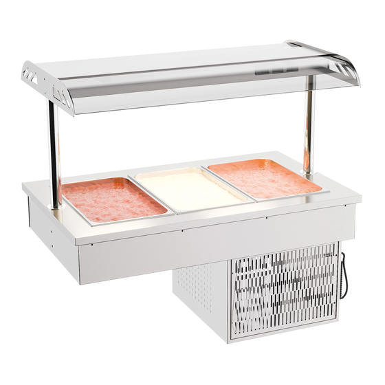
- Page 10 Digital control panel Tank Height 110mm Dimension are given in ''mm'' Max 1/1x100mm G/N Pan Capacity (Pans are placed for visual purposes) Figure B According to Customer Request According to Customer Request Engine Grid Discharge Surface Discharge Size 1170/1470/1770x700mm Figure C...
- Page 11 Product Support: Help is always at hand: All repairs to the machine must be carried out by an authorised repair agent. When a repair is required or you are unable to eliminate the failure with the help of the information below: PROBLEM SOLVE Check the plot lamp.
-
Page 12: Electrical Connection Drawing
D. ELECTRICAL CONNECTION DRAWING 7178.2040 / 7178.2045 / 7178.2050 L – PHASE N – NOTR PE – GROUNDING 0-1 – ON-OF SWITCH LD – LED SL – SIGNAL LAMP R – RELAY DT – DIGITAL THERMOSTAT T – THERMIC K – COMPRESSOR C –... - Page 13 Compatibility Information This device is designed and manufactured in accordance with the following directives and standards. marking directive, 93/68/EEC IEC 60335-1:2020/AC IEC 60335-2-89:2022 Related to CE Directive(s): 2014/35/EU (Low Voltage) • Limitation of Liability: All technical information contained in this manual, operating instructions, operation and maintenance of the device, contains the latest information on your device.
- Page 14 Handleiding Voor Bediening En Onderhoud Ingebouwde koudeservice-eenheid...
-
Page 15: Beschrijvingen
7. Schade aan de interne componenten van het product of onderdeel als gevolg van risico's, schade en storingen die kunnen optreden in de volgende situaties en schade aan materiële en morele schade die door de gebruikers kan worden ervaren. COMBISTEEL HET IS NIET VERANTWOORDELIJK. Alle technische, administratieve, financiële en strafrechtelijke aansprakelijkheid ligt bij de gebruiker. - Page 16 Bediening of gebruik van het product in strijd met de instructies gegeven in de installatie-, gebruiks- en onderhoudsinstructies. Gebruik van het product anders dan geautoriseerde service en reparatie. Het verwijderen van de labels op het product, waardoor het serienummer wordt vernietigd.
-
Page 17: Installatie En Gebruk
WEERGAVE EN AANPASSEN VAN INSTELLINGSWAARDEN: Houd de SET-toets 2 seconden ingedrukt om de ingestelde waarden en weer te geven De eenheid knippert in °C. Met de UP- en DOWN-toetsen kunt u de waarden instellen en vervolgens bevestigen door op de SET-toets te drukken. HET TOETSENBORD VERGRENDELEN: Wanneer de UP- en DOWN-toetsen tegelijkertijd gedurende 3 seconden worden ingedrukt, wordt het toetsenbord vergrendeld en wordt het bericht "POF"... - Page 18 Om de verlichting op het apparaat in te schakelen, wordt de oranje knop (3) op het paneel (Fig. A) in de stand "lamp" gedraaid. Neem voor alle andere instellingen contact op met de geautoriseerde service. 4. Het apparaat uitschakelen De verlichtingsknop (3) op het paneel wordt uit de lampstand gehaald en de groene knop (1) uit de koelstand.
-
Page 19: Producttekeningen
C. PRODUCTTEKENINGEN Breedte Diepte Hoogte Stroom Elektrische Product Kabelsecties Gewicht Volume (50-60 Hz) inlaat 1200 1050 7178.2040 1 kW 230V 1N PE 3x1,5mm 80 kg 1,30 m 1500 1050 7178.2045 1 kW 230V 1N PE 3x1,5mm 100 kg 1,48 m... - Page 20 7178.2045 7178.2050...
- Page 21 Digitaal Tankhoogte 110 mm bedieningspaneel Afmeting wordt gegeven in ''mm'' Max. 1/1x100 mm GN-pancapaciteit (Pannen worden geplaatst voor visuele doeleinden) Figuur B Volgens klantenverzoek Volgens klantenverzoek Ontlading van het motorrooster Oppervlakte ontladingsgrootte 1170/1470/1770x700mm Figuur C...
- Page 22 Product ondersteuning: Er is altijd hulp beschikbaar: Alle reparaties aan de machine moeten worden uitgevoerd door een erkende reparateur. Wanneer een reparatie nodig is of u de storing niet kunt verhelpen met behulp van de onderstaande informatie: PROBLEEM OPLOSSEN Controleer de plotlamp. Als de plotlamp niet werkt, wordt de Koelkast werkt niet.
-
Page 23: Electrische Aansluiting Tekening
D. ELEKTRISCHE AANSLUITING TEKENING 7178.2040 / 7178.2045 / 7178.2050 L – FASE N – NOTR PE – AARDING 0-1 – AAN-UIT-SCHAKELAAR LD - LED SL – SIGNAALLAMP R – RELAIS DT – DIGITALE THERMOSTAAT T – THERMISCH K – COMPRESSOR C –... - Page 24 Compatibiliteitsinformatie Dit apparaat is ontworpen en vervaardigd in overeenstemming met de volgende richtlijnen en normen. markeringsrichtlijn, 93/68/EEG IEC 60335-1:2020/AC IEC 60335-2-89:2022 Gerelateerd aan CE- richtlijn(en): 2014/35/EU (laagspanning) • Beperking van aansprakelijkheid: Alle technische informatie in deze handleiding, bedieningsinstructies, bediening en onderhoud van het apparaat, bevat de nieuwste informatie over uw apparaat.
- Page 25 Betriebs- und Wartungsanleitung Eingebaute Kühleinheit...
-
Page 26: Beschreibungen
5. Mängel, die durch die Verwendung des Produkts entgegen den Installations-, Nutzungs- und Wartungsvorschriften entstehen, fallen nicht unter die Garantie. 6. Die Aufbewahrung der durch die neue Garantie ersetzten Altteile bleibt COMBISTEEL 7. Schäden an den internen Komponenten des Produkts oder Teils aufgrund von Risiken, Schäden und Fehlfunktionen, die in den folgenden Situationen auftreten können, sowie... - Page 27 Entfernen der Etiketten am Produkt, Zerstörung der Seriennummer. Streik bei Naturkatastrophen wie Feuer, Erdbeben, Überschwemmung, Blitzschlag, Aufenthalt in der Aussperrumgebung, Schäden. 8. Elektrische Produkte; Die Hauptschalttafel, die das Produkt ohne ordnungsgemäße Erdungsinstallation mit Strom versorgt, und das Leckstromrelais sollten nicht ohne Installation der Versicherungsgruppen betrieben werden.
-
Page 28: Installation Und Verwendung
ANZEIGE UND ANPASSUNG DER EINSTELLWERTE: Halten Sie die SET-Taste 2 Sekunden lang gedrückt, um die eingestellten Werte anzuzeigen Die Einheit blinkt in °C. Sie können die Werte mit den UP- und DOWN-Tasten einstellen und anschließend mit der SET-Taste bestätigen. SPERREN DER TASTATUR: Wenn die AUF- und AB-Tasten gleichzeitig 3 Sekunden lang gedrückt werden, wird die Tastatur gesperrt und die Meldung "POF"... - Page 29 Wenn die Drop-in-Kaltdisplayeinheit die gewünschte Temperatur erreicht, ist sie einsatzbereit. Um die Beleuchtung am Gerät einzuschalten, wird der orangefarbene Knopf (3) auf dem Bedienfeld (Abb. A) in die Position "Lampe" gedreht. Für alle anderen Einstellungen wenden Sie sich an den autorisierten Service. 4.
-
Page 30: Produktzeichnungen
C. PRODUKTZEICHNUNGEN Breite Tiefe Höhe Leistung Elektrischer Produkt Kabelabschnitte Gewicht Volumen (50-60 Hz) Eingang 1200 1050 7178.2040 1 kW 230V 1N PE 3x1,5mm 80 kg 1,30 m 1500 1050 7178.2045 1 kW 230V 1N PE 3x1,5mm 100 kg 1,48 m... - Page 31 7178.2045 7178.2050...
- Page 32 Digitales Bedienfeld Tankhöhe 110 mm Die Abmessungen werden in ''mm'' angegeben. Maximale Kapazität von 1/1 x 100 mm GN-Pfanne (Pfannen werden zu visuellen Zwecken platziert) Abbildung B Nach Kundenwunsch Nach Kundenwunsch Motorgitterentladung Größe der Oberflächenentladung 1170/1470/1770x700mm Abbildung C...
- Page 33 Produkt Support: Hilfe ist immer zur Hand: Alle Reparaturen an der Maschine müssen von einem autorisierten Reparaturbetrieb durchgeführt werden. Wenn eine Reparatur erforderlich ist oder Sie den Fehler mit Hilfe der folgenden Informationen nicht beheben können: PROBLEM LÖSEN Überprüfen Sie die Plotlampe. Wenn die Plotlampe nicht Kühlschrank funktioniert nicht.
-
Page 34: Elektrische Anschlusszeichnung
D. ELEKTRISCHE ANSCHLUSSZEICHNUNG 7178.2040 / 7178.2045 / 7178.2050 L – PHASE N – NOTR PE – ERDUNG 0-1 – EIN-AUS-SCHALTER LD – LED SL – SIGNALLAMPE R – RELAIS DT – DIGITALER THERMOSTAT T – THERMISCH K – KOMPRESSOR C – CONDANSER KF –... - Page 35 Kompatibilitätsinformationen Dieses Gerät wurde in Übereinstimmung mit den folgenden Richtlinien und Normen entwickelt und hergestellt. Kennzeichnungsrichtlinie 93/68/EWG IEC 60335-1:2020/AC IEC 60335-2-89:2022 Bezogen auf CE- Richtlinie(n): 2014/35/EU (Niederspannung) • Haftungsbeschränkung: Alle in diesem Handbuch enthaltenen technischen Informationen, Bedienungsanleitungen, Bedienung und Wartung des Geräts enthalten die neuesten Informationen zu Ihrem Gerät.
- Page 36 Manuel d’Utilisation et de Maintenance Unité de service à froid intégrée...
-
Page 37: Description
Votre COMBISTEEL préféré, la nature et la technologie sont conviviales, merci pour votre choix. • COMBISTEEL a été produit avec le concept de "qualité totale" dans des installations de production modernes. Alertes de sécurité Lisez attentivement ce manuel et conservez-le pour consultation future. - Page 38 Fonctionnement ou utilisation du produit en contradiction avec les instructions données dans la notice d'installation, d'utilisation et d'entretien. Fonctionnement du produit autre que le service autorisé, réparation. Retirer les étiquettes du produit, détruire le numéro de série. Frappez en cas de catastrophe naturelle telle qu'un incendie, un tremblement de terre, une inondation, la foudre, pour rester dans un environnement de verrouillage, des dommages.
-
Page 39: Installation Et Utilisation
AFFICHAGE ET RÉGLAGE DES VALEURS DE RÉGLAGE : Appuyez et maintenez la touche SET pendant 2 secondes pour afficher les valeurs définies et L'unité clignote en °C. Vous pouvez régler les valeurs avec les touches UP et DOWN puis confirmer en appuyant sur la touche SET. - Page 40 Lorsque l’unité de présentation froide encastrable atteint la température souhaitée, elle est prête à l’emploi. Pour allumer les lumières de l'appareil, le bouton orange (3) du panneau (Fig. A) est tourné sur la position « lampe ». Pour tous les autres réglages, contactez le service agréé. 4.
-
Page 41: Dessins De Produits
Largeur Profondeur Hauteur Pouvoir Entrée Sections Produit Poids Volume (50-60 Hz) électrique de câbles 230V 1N 7178.2040 1200 mm 730 mm 1050 mm 1 kW 3x1,5mm 80 kg 1,30 m 230V 1N 7178.2045 1500 mm 730 mm 1050 mm 1 kW... - Page 42 7178.2045 7178.2050...
- Page 43 Panneau de commande Hauteur du réservoir 110 mm numérique Les dimensions sont données en ''mm'' Capacité maximale du bac GN 1/1 x 100 mm (Les casseroles sont placées à des fins visuelles) Figure B Selon la demande du client Selon la demande du client Décharge du réseau moteur Taille de décharge de surface 1170/1470/1770x700mm...
- Page 44 Support produit: L'aide est toujours à portée de main : Toutes les réparations de la machine doivent être effectuées par un réparateur agréé. Lorsqu'une réparation est nécessaire ou que vous ne parvenez pas à éliminer la panne à l'aide des informations ci-dessous : PROBLÈME RÉSOUDRE Vérifiez la lampe de tracé.
-
Page 45: Schéma De Connexion Électrique
D. SCHÉMA DE CONNEXION ÉLECTRIQUE 7178.2040 / 7178.2045 / 7178.2050 L - PHASE N – NOTR PE – MISE À LA TERRE 0-1 – INTERRUPTEUR MARCHE LD - LED SL – LAMPE DE SIGNALISATION R – RELAIS DT – THERMOSTAT NUMÉRIQUE T –... - Page 46 Informations de compatibilité Cet appareil est conçu et fabriqué conformément aux directives et normes suivantes. directive de marquage, 93/68/CEE IEC 60335-1:2020/AC IEC 60335-2-89:2022 Concernant les directives CE : 2014/35/UE (basse tension) • Limitation de responsabilité : Toutes les informations techniques contenues dans ce manuel, les instructions d'utilisation, le fonctionnement et la maintenance de l'appareil, contiennent les dernières informations sur votre appareil.
- Page 47 Combisteel BV Office: Lichtschip 63, 3991 CP, Houten, The Netherlands Warehouse: Verlengde Gildenweg 20, 8304 BK, Emmeloord, The Netherlands TEL: +31 (0)30 285 00 90 E-mail: info@combisteel.com www.combisteel.com...
Need help?
Do you have a question about the 7178.2040 and is the answer not in the manual?
Questions and answers