Table of Contents
Advertisement
Quick Links
Advertisement
Table of Contents

Related Manuals for Gima DIATERMO MB 200 T


Summary of Contents for Gima DIATERMO MB 200 T
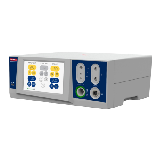
- Page 1 DIATERMO MB 200 T ELECTROSURGICAL UNIT USER MANUAL...
-
Page 3: Table Of Contents
SUMMARY IMPORTANT ........................................3 INTRODUCTION ......................................4 STANDARD AND OPTIONAL COMPOSITION ..........................4 GENERAL DESCRIPTION..................................6 INTENDED USE ....................................... 7 TARGET USER ......................................7 TARGET PATIENT POPULATION ..............................7 ELECTROPHYSICAL PRINCIPLES ................................8 OPERATIVE TECHNICS .................................... 11 MONOPOLAR CUT ....................................11 MONOPOLAR COAGULATION ............................... - Page 4 AUTOSTART AND AUTOSTOP ............................. 35 DISPENSING SCREEN ................................37 FLASH TIMER SECTION ................................37 PROGRAMS SECTION ................................38 NEUTRAL ELECTRODE CONTROL ............................39 LIGHTS ......................................40 SETTINGS ...................................... 41 UPDATE ......................................42 BACK PANEL ....................................... 43 POWER SUPPLY MODULE OF THE EQUIPMENT AND VOLTAGE SELECTOR ............... 43 POWER SWITCH ....................................
-
Page 5: Important
IMPORTANT This instruction manual represents an essential part of the HF electrosurgery unit and must be kept available to the operating staff at all times. It is of paramount importance to carefully read and fully understand all instructions and guidelines before attempting any use of an active electrode. It is imperative to diligently follow all warnings and safety instructions. -
Page 6: Introduction
INTRODUCTION STANDARD AND OPTIONAL COMPOSITION Code Description DIATERMO MB 200 T Electrosurgical unit code GMA10100.T40 00100.01 Power supply cable 5m SIE-IEC ■/1 00202.00 Holder for Handle and Electrodes ■/1 00205.00 PENCIL S - Handle with Switch ■/1 00304.00 Water-proof foot switch ■/1... - Page 7 Code Description DIATERMO MB 200 T 310-110-05 BIPOLAR - Bipolar Forceps 11,5cm TIP0.5mm ○ 310-112-05 BIPOLAR - Bipolar Forceps Curved 11,5cm TIP0.5mm ○ 310-140-10 BIPOLAR - Bipolar Forceps 20cm TIP 1mm ○ 310-140-20 BIPOLAR - Bipolar Forceps 20cm TIP 2mm ○...
-
Page 8: General Description
GENERAL DESCRIPTION The high-frequency electrosurgical device is capable of providing current for monopolar cutting, coagulated cutting with different levels of coagulation, both in monopolar and bipolar modes. In bipolar coagulation mode, it is possible to activate a tissue impedance detection system with automatic start and automatic stop once coagulation is achieved (AUTOSTART - AUTOSTOP functions). -
Page 9: Intended Use
The DIATERMO MB 200 T equipment is conceived for being used in the following sectors: DIATERMO... -
Page 10: Electrophysical Principles
ELECTROPHYSICAL PRINCIPLES In electrosurgical interventions the traditional use of surgical blade is substituted by an electrosurgical needle that allows for fast and effective cut and coagulation of the targeted tissue. The electrosurgical needle operates on the principle of converting electrical energy into heat and consists of the following components: A radiofrequency sinusoidal oscillator (0.4 - 4MHz). - Page 11 State of active electrode • Thermal effects can be related to the resistance of the human body to which the contact resistance of the electrode must be added. It is essential to keep the active electrodes perfectly clean in order not to have a reduction in the effects. Characteristics of the tissue •...
- Page 12 in surgical procedures, have the shape of the edge of the neutral electrode. To reduce the risk of burns, it is necessary to dose the delivered power (I ∙t) appropriately and follow the rules for applying the neutral electrode to the patient (see SAFETY chapter). Faradic Effect Pulsed electric current causes neuro-muscular stimulation, originating from the stimulation of the physiological process of ion exchange, which is responsible for the transmission of stimuli that cause...
-
Page 13: Operative Technics
OPERATIVE TECHNICS MONOPOLAR CUT Monopolar cutting is a technique used to dissect biological tissue by directing a high-frequency, high- density electrical current from the active electrode's tip. This current generates intense molecular heat within the cells, causing them to rupture. As the electrode moves through the tissue, it shears and destroys cells sequentially. -
Page 14: Bipolar Coagulation
Coagulation can be achieved through two different methods: Coagulation by Desiccation • This is achieved by supplying the electrode with low voltages to prevent the generation of sparks (ensuring that the action obtained is pure coagulation without any cutting effect). The electrode is placed in direct contact with the tissue, and the amount of heat generated on contact dries it out. -
Page 15: Contraindications
CONTRAINDICATIONS The use of electrosurgery is contraindicated in patients: pacemaker carriers • with stimulation electrodes • with metallic prostheses • with serious blood pressure imbalances • with serious diseases of the nervous system • with serious kidney failure • in state of pregnancy. •... -
Page 16: Safety
SAFETY WARNING: Electrosurgery carries inherent risks, and improper usage of any component within the electrosurgical system can result in severe burns to the patient. It is absolutely crucial that you meticulously read and comprehensively understand all instructions before attempting to utilize an active electrode. - Page 17 This unit has a CQM system; please note that the loss of secure contact between the neutral • electrode and the patient will not trigger an alarm unless a compatible monitoring neutral electrode (split neutral electrode) is used. CAUTION: Set the intensity to the lowest level necessary to achieve the desired effect. •...
-
Page 18: General
GENERAL The following precautions are crucial for minimizing the risk of inadvertent burns: Ensure the secure and complete attachment of the neutral electrode to the patient's body, • preferably at the extremities and as close to the surgical site as possible. Avoid connecting the neutral electrode to bony protrusions, prosthetic devices, areas with scar tissue, regions susceptible to fluid accumulation, or areas with a thick layer of subcutaneous fat. - Page 19 To avoid skin-to-skin contact (e.g., between the arm and trunk, between the legs, or on the breasts), • it's allowed to insert dry gauze. Additionally, ensure that body areas prone to profuse sweating are kept dry. Active Electrode Neutral Electrode –...
- Page 20 Be aware that certain materials, such as cotton wool or gauze impregnated with oxygen, may ignite • due to sparks produced by the appliance under normal conditions. Take necessary precautions to prevent such incidents. Patients with pacemakers or pacing electrodes are at risk of interference with their pacemaker's •...
-
Page 21: Installation
INSTALLATION Electrical safety is guaranteed only when the equipment is correctly connected to a reliable power ▪ supply network with proper grounding, in compliance with current safety standards. It is essential to ensure this fundamental safety requirement, and if there are any doubts, seek a comprehensive inspection of the system by qualified personnel. -
Page 22: Patient Safety
PATIENT SAFETY During high-frequency electrosurgery procedures, it's crucial to understand that the patient becomes a conductor of electrical voltage relative to the earth potential. Consequently, if there is contact between the patient and electrically conductive objects (such as metal objects, damp or wet sheets, cloths, etc.), it can result in the generation of electric current at the point of contact. - Page 23 Ensuring the correct placement of the neutral electrode is of utmost importance to prevent burns and minimize patient risks. Below are some valuable tips to achieve this: 1. Correct positioning In the image alongside, the correct positioning of the split neutral electrode is illustrated.
-
Page 24: High-Frequency Electrosurgery In Laparoscopy
For both single-part and dual-part electrodes, before proceeding with the placement of the neutral electrode, clean and remove any residues of foreign substances from its surface. Do not apply the neutral electrode on scars, bony prominences, or anatomical areas where prosthetic implants or monitoring electrodes are present. - Page 25 Furthermore, within the surgical environment, where the active electrode closely interacts with conductive instruments and bodily tissue, there are factors that can promote the transfer of electrical currents to concealed areas. These factors include: 1. Direct Coupling: This occurs when the active electrode makes contact with another metal instrument, leading to the transmission of electrical current and an increased risk of burns to nearby tissue, such as the intestines or other organs.
-
Page 26: Putting Into Service
PUTTING INTO SERVICE Inspect the Equipment for Shipping Damage: Check the equipment for any damage caused during • shipping. If you find any damage, please report it immediately to the carrier and document the damage found. You should also inform LED SpA or your seller. When returning the equipment, use the original packaging or packaging that ensures safe transport. -
Page 27: Connection And Use Of Accessories
CONNECTION AND USE OF ACCESSORIES Depending on the unique requirements of each procedure, there may be a need for optional accessories. These accessories are designed to cater to specific demands, enhance precision, or optimize the outcomes of the procedure. Some examples of optional accessories may include: For the bipolar procedure •... -
Page 28: Connectors And Controls
CONNECTORS AND CONTROLS LABEL ON REAR PANEL Safety requirements for high-frequency (HF) surgical equipment necessitate the clear printing of data and symbols on the cabinet, or at the very least, on one of the panels of the power unit. These data and symbols serve a crucial role in defining the equipment's characteristics and monitoring its operational conditions to guarantee safe and effective utilization of the device. -
Page 29: Meaning Of Graphic Symbols
MEANING OF GRAPHIC SYMBOLS N° SYMBOL DESCRIPTION Floating neutral electrode: not connected to ground at either high or low frequencies. CF Class equipment protected against defibrillator-induced discharge. Non-ionising radiation generator equipment. Follow the instructions for use. CE Mark (2017/745/EU) + Notified Body Number 0051 = IMQ Italy. The product should not be disposed of in urban waste containers but must be disposed of through separate collection. -
Page 30: Box Label
BOX LABEL With reference ISO15223-1 “Medical Devices-Symbols to be used with medical device, labels, labelling and information to be supplied” and ISO780 “Packaging – Pictorial marking for handling of goods” On box label of UNIT’s carton box are present these indications: 1. -
Page 31: Front Panel
FRONT PANEL 1. USB PORT To perform software updates, use the USB 2.0 port located on the front of the unit. 2. TOUCHSCREEN DISPLAY The backlit LCD touchscreen display allows for the visualization and selection of all set and adjustable parameters within a specific procedure. 3. -
Page 32: Operating Modes
OPERATING MODES CONTROL AND POWER ON The unit is operated directly through the icons displayed on the touchscreen of the device. To confirm a selection, simply touch the icon. Once the electrosurgical unit is powered on, the specific software begins to load on the screen. The progress of the software application process is indicated by the filling of the bar at the bottom of the screen. -
Page 33: Programs
PROGRAMS “Programs” By selecting the option on the home screen, two separate pages will open: 1. Preset: In this section, pre-configured programs that have already been set up and stored in the system will be displayed. These represent standard settings for a variety of common surgical procedures. -
Page 34: Surgery
The distinction between these two pages allows operators to easily access a range of predefined or customized settings, depending on the specific requirements of the surgical procedure. This provides flexibility in selecting settings according to the context. 'Help' Furthermore, by pressing on the display, you can obtain information about the features of 'Back' the selected program. -
Page 35: Monopolar Section
MONOPOLAR SECTION In the sections dedicated to adjusting cutting or coagulation, both in monopolar and bipolar modes, there are three icons: Icon for adjusting the output power By tapping the icon with the number, you can adjust the output power. Below is an example to illustrate the procedure: Pressing the '+' and '-' buttons adjusts the power, while pressing the '✓' button confirms the selected value. - Page 36 FORCED COAG CURRENT (FORCED COAG) The modulated current (FORCED COAG) has good surface coagulative properties but may also lead to the potential formation of eschar and slight tissue carbonization. The advantage of this type of coagulation lies in the speed at which the desired effect is achieved.
-
Page 37: Bipolar Section
BIPOLAR SECTION In the bipolar section, just like in the monopolar section, you can adjust the output power, select the deliverable current, and activate the footswitch. The difference lies in the mode-specific selectable functions for each mode. You will need to connect the bipolar accessories to the connectors for this function and use the pedal switch. - Page 38 START • start bipolar start sealing To activate the " " or " " function, you need to press the pedal, establish contact between the active electrode and the tissue, and this will activate the output. If you wish to stop, simply release the pedal.
-
Page 39: Dispensing Screen
DISPENSING SCREEN In the dispensing state, the screen will display the function along with its respective level. This screen remains for a few seconds during which you can adjust the output level using the + and - buttons. FLASH TIMER SECTION continuous Through the “FLASH TIMER”... -
Page 40: Programs Section
PROGRAMS SECTION “Surgery' In the ” screen, you can add a custom program or view the existing programs. To create a new program, follow the following procedure: • Set the desired values in the 'Surgery' screen. • Press '+ save' and choose the name to assign, completing the process by clicking 'enter'. The new customized programs can be viewed in the 'Programs' section. -
Page 41: Neutral Electrode Control
Through the icon representing three lines, you can perform various actions on the customized program: Rename it. Modify it. Delete it. NEUTRAL ELECTRODE CONTROL The neutral electrode circuit is continuously monitored by a special circuit. This circuit checks, especially when bipartite neutral electrodes are in use, for any loss of contact between the patient reference plate or changes in the conductivity characteristics of the neutral electrode. -
Page 42: Lights
LIGHTS 1. Monopolar Output Connector 2. Monopolar Output Indicator, which has three modes: Off Indicator – Monopolar functions off (tap on the display "MONOPOLAR" to turn on • and off the section) Yellow Indicator – Cut current output • Blue Indicator – Coagulation current output •... -
Page 43: Settings
SETTINGS Settings Starting from the home page and selecting the " " option will bring up the following screen: Through this screen, you will be able to access three sections: Language. • Display, where you can adjust brightness, touchscreen sensitivity, volume, and switch between •... -
Page 44: Update
UPDATE Starting from the home page and choosing the "Update" option, you can update: Software • Images • Protocols • Firmware • To perform updates, you need to connect a compatible device to the USB connector, which contains the compatible file for the software, images, protocols, or firmware to be updated. Follow these steps: 1. -
Page 45: Back Panel
BACK PANEL 1. Power Socket 2. Power Switch 3. Fuse Holder / Voltage Selector 4. Equipotential Socket POWER SUPPLY MODULE OF THE EQUIPMENT AND VOLTAGE SELECTOR The equipment's power supply module serves as the connection point for supplying power to the internal electronics of the equipment. -
Page 46: Technical Characteristics
TECHNICAL CHARACTERISTICS DIATERMO MB Tolerance Description 200 T Electrosurgical unit code GMA10100.T40 ● Detection system of tissue impedance (Bipolar coagulation – auto start/autostop) ● Bipolar coag with automatic activation/disactivation Minimum preselectable power ● Selection of the power through touch screen ±... -
Page 47: Hardware Requirements
DIATERMO MB Tolerance Description 200 T ● Power accuracy output warning ● Skin Plate Electronic Control ● Split or not split patient plate allowed Working (CUSTOM) condition storing More than 50 Class I Electrical Class (EN60601-1) Applicated Part MDR 2017/45/UE Class II b IP Protection Class (EN 60529) IP32... -
Page 48: Maintenance
MAINTENANCE GENERAL There are no user-adjustable parts inside the equipment for calibration or service purposes. Opening the equipment casing voids the warranty. If repair or adjustment is necessary, the entire equipment should be sent to the LED SpA service center in APRILIA (LT), ITALY, along with a description of the issue. User maintenance primarily involves cleaning and sterilizing accessories and performing equipment checks before each use. -
Page 49: Guide To Troubleshooting
GUIDE TO TROUBLESHOOTING If you encounter any problems, it's crucial to verify that the installation and accessory setup have been executed correctly. The error code shown on the seven-segment display, along with the description on the LCD display, can offer valuable insights for diagnosing and resolving the issue. Problems Probable Cause Solution... -
Page 50: Pre-Use Unit Check
PRE-USE UNIT CHECK Whenever the unit is scheduled for use, it is essential to perform a safety check, considering the following points: Inspect the integrity of cables, connections, wire breakage, etc. • Ensure that all electrical equipment is properly grounded. •... -
Page 51: Diagrams
DIAGRAMS BLEND 100% 100% Load (Ohms) Load (Ohms) Diagrams of half and maximum output power versus impedance Diagrams of half and maximum output power versus impedance load 100-2000 CUT100% load 100-2000 BLEND FORCED COAG ENHANCED 100% 100% Load (Ohms) Load (Ohms) Diagrams of half and maximum output power versus impedance Diagrams of half and maximum output power versus impedance load 100-2000... - Page 52 BIPOLAR COAG BIPOLAR VESSEL 100% 100% Load (Ohms) Load (Ohms) Diagrams of half and maximum output power versus impedance Diagrams of half and maximum output power versus impedance load 10-1000 BIPOLAR COAG load 10-1000 BIPOLAR VESSEL CUT - 300 OHM BLEND - 300 OHM Setting Setting...
- Page 53 BIPOLAR CUT - 50 OHM BIPOLAR TUR - 50 OHM Setting Setting Diagrams of output power versus nominal value Diagrams of output power versus nominal value BIPOLAR CUT BIPOLAR TUR BIPOLAR COAG - 50 OHM BIPOLAR VESSEL - 50 OHM Setting Setting Diagrams of output power versus nominal value...
- Page 54 SOFT COAG - Vpeak max FULGURATION - Vpeak max 2500 2000 1500 1000 Setting Setting Diagrams of maximum mains voltage output versus Vp Diagrams of maximum mains voltage output versus Vp SOFT COAG FULGURATION BIPOLAR CUT - Vpeak max BIPOLAR TUR - Vpeak max 100 110 120 Setting Setting...
- Page 56 Official Dealer GIMA SPA Via Marconi 1 - 20060 Gessate (MI) - ITALY Tel +39 02 9538541 Fax +39 02 95381167 www.gimaitaly.com gima@gimaitaly.com - export@gimaitaly.com...
Need help?
Do you have a question about the DIATERMO MB 200 T and is the answer not in the manual?
Questions and answers