Gima OXY-200 Instructions To User
Hide thumbs
Also See for OXY-200:
- User manual (28 pages) ,
- User manual (124 pages) ,
- Instructions to user (128 pages)
Table of Contents
Advertisement
Quick Links
PROFESSIONAL MEDICAL PRODUCTS
PULSOXIMETRO OXY-200
OXY-200 PULSE OXIMETER
OXYMÈTRE DE POULS OXY-200
PULSIOXÍMETRO OXY-200
(GIMA 35213)
CMS70A
CONTEC MEDICAL SYSTEMS CO., LTD
No.112 Qinhuang West Street,
Economic & Technical Development Zone,
066004 Qinhuangdao, Hebei Province,
PEOPLE'S REPUBLIC OF CHINA
Made in China
Shanghai International Holding Corp. GmbH (Europe)
Eiffestrasse 80, 20537 Hamburg, Germany
Importato da / Imported by / Importé par / Importado por:
Gima S.p.A.
Via Marconi, 1 - 20060 Gessate (MI) Italy
gima@gimaitaly.com - export@gimaitaly.com
www.gimaitaly.com
IP21
0123
Advertisement
Table of Contents

Related Manuals for Gima OXY-200


Summary of Contents for Gima OXY-200
- Page 1 PROFESSIONAL MEDICAL PRODUCTS PULSOXIMETRO OXY-200 OXY-200 PULSE OXIMETER OXYMÈTRE DE POULS OXY-200 PULSIOXÍMETRO OXY-200 (GIMA 35213) CMS70A CONTEC MEDICAL SYSTEMS CO., LTD No.112 Qinhuang West Street, Economic & Technical Development Zone, 066004 Qinhuangdao, Hebei Province, PEOPLE’S REPUBLIC OF CHINA Made in China...
- Page 2 ENGLISH Instructions to User Dear users, thank you very much for purchasing the Pulse Oximeter (hereinafter referred to as device). This Manual is written and compiled in accordance with the council directive MDD93/42/EEC for medical devices and harmonized standards. In case of modifications and software upgrades, the information contained in this document is subject to change without notice.
- Page 3 ENGLISH When the message “Sensor Off” or “Sensor Fault” appears on the screen, it indicates that the SpO probe is disconnected or line fault occurs. Check the connection of the SpO probe and whether there is damage for the probe, if necessary, please replace the probe to avoid risks. The probe fault will not result in a safety hazard.
-
Page 4: Table Of Contents
ENGLISH CONTENTS 1 Overview ............................28 1.1 Features ............................28 1.2 Indication for Use ........................29 1.3 Environment Requirements.......................29 1.4 Precautions ..........................29 2 Principle ............................31 3 Functions ............................31 4 Installation ............................32 4.1 Appearance ..........................32 4.2 Interface introduction.........................33 4.3 SpO2 probe installation ......................33 4.4 Connection of data line ......................33 4.5 Structure, accessories and software description............... -
Page 5: Indication For Use
ENGLISH 1.2 Indication for Use The Pulse Oximeter can be used in measuring the pulse oxygen saturation and pulse rate through finger. The product is suitable for being used in family, hospital, oxygen bar, community healthcare, physical care in sports (It can be used before or after doing sports, and it is not recommended to use the device during the process of having sport) and etc. - Page 6 ENGLISH If necessary, please visit our official website to get the information about SpO probe that can be used with this device. If the device or component is intended for single-use, then the repeated use of these parts will pose risks on the parameters and technical parameters of the equipment known to the manufacturer.
-
Page 7: Principle
ENGLISH 2 PRINCIPLE Glow and Infrared ray Emission Tube Glow and Infrared ray Receipt Tube Figure 1. Operating principle Principle of the Oximeter is as follows: An experience formula of data process is established taking use of Lambert Beer Law according to Spectrum Absorption Characteristics of Reductive Hemoglobin (Hb) and Oxyhemoglobin (HbO ) in glow &... -
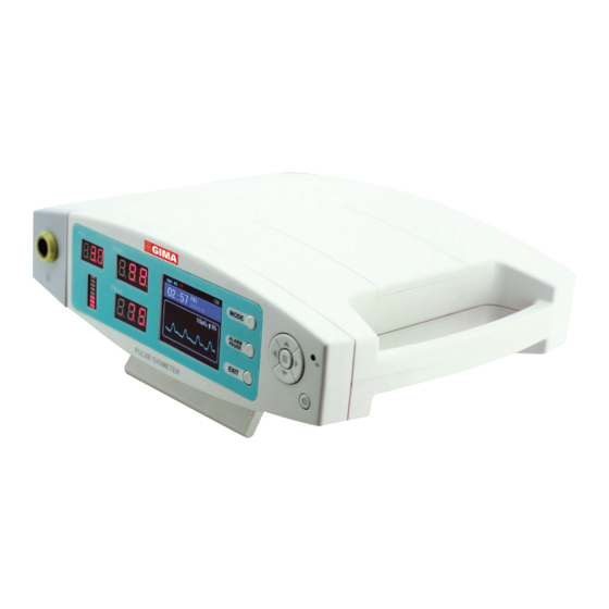
Page 8: Installation
ENGLISH 4 INSTALLATION 4.1 Appearance Figure 2. Appearance Alternating current indicator lint: the light is green when powered on. Probe jack: it is used to connect Oximeter probe to measure the oxygen saturation, pulse rate and PI. Alarm lamp: When data’s going beyond the limits, low-voltage, finger out, sensor off or sensor fault, the alarm light will be on. -
Page 9: Interface Introduction
ENGLISH 4.2 Interface introduction Figure 3. Measurement interface 4.3 SpO2 probe installation Inserting the lemo probe into the lemo jack of the device (The probe is limited to the one that is provided by our company; and can’t be replaced with the similar one by other manufacturers). 4.4 Connection of data line Please connect the data line to device, the other end into computer. -
Page 10: Measurement Interface
ENGLISH A. Short press power button to turn on the device. If use alternating current, make sure that the power supply line is connected accurately. B. Do not shake the finger and keep the patient in a stable state during the process. C. - Page 11 ENGLISH F. Factory Default: move the choice bar to the “Factory Default” item, enter the password in the pop- up interface(Please refer to chapter 5.3.4), then press the menu button to pop-up “Factory Default” window. Press up/down button to choose whether to resume Factory Default, and press menu button to affirm setting, then press return button to return the system setting menu interface.
- Page 12 ENGLISH 5.3.3 Clock setting In the main menu interface, move the choice bar to “Clock” item, then press the menu button to enter the clock setting menu of Figure 10: Figure 10. Clock setting menu Move the choice bar to the menu item that you want to set, and press left/right button to begin to set. After resetting time, press return button to return to the main menu.
- Page 13 ENGLISH A. Set the high/low limit of alarm In alarm setting menu, you can set the high/low limit of alarm. Move the choice bar to the menu item that you want to set, and press left/right button to set value, then press menu button for affirming. Note: If the alarm function is on, the device will provide alarm sound when the measure value is beyond the limit.
- Page 14 ENGLISH 5.3.5 Record setting In the main menu interface, move the choice bar to “Record” item, then press menu button to enter record menu as Figure 15. Figure 15. Record Menu A Record setting a. In the record menu interface, move the choice bar to “Record” item, then press left/ right button to choose on/ off.
- Page 15 ENGLISH d. Every patient ID could save 24-hour data, the device could save 16 patient ID. e. When the memory is full, the system will stop recording automatically. f. When the 16 groups of ID all have data, click “record” menu again, the device will appear “No Mem- ory”...
-
Page 16: Data Upload
ENGLISH Figure 20. Select ID interface Choose the review record and press menu button to enter the review interface. Choose “VALUE” to enter true value review interface as figure 21. Choose “TREND” to enter trend review interface as figure Figure 21. VALUE review interface Figure 22. -
Page 17: Charging
ENGLISH 5.5. Charging Connect the device to power supply with power line. Note: When the device is closed and the battery is charging up, short press power button and the device will display dynamic charge icon, it means that the device is charging up. When the battery status is full, the charging has been finished. -
Page 18: Troubleshooting
ENGLISH 7 TROUBLESHOOTING Trouble Possible Reason Solution The values can not be 1) 1.The finger is not properly inserted. 1) Please insert the finger properly displayed normally or stably. 2) The finger is shaking or the patient is and measure again. moving. -
Page 19: Specification
ENGLISH The sensor is off (probe-off) Manufacturer SENSOR OFF Alternating current indicator light Temperature limit IP21 Covering Protection rate Atmospheric pressure limit Date of manufacture Fragile, handle with care Humidity limit Recovery This side up Lot number Authorized representative in the Keep in a cool, dry place European community Material code... -
Page 20: Factory Default
ENGLISH Optical sensor [see note 5] Red light Wavelength: about 660 nm, optical output power: < 6.65 mW Infrared light Wavelength: about 905 nm, optical output power: < 6.75 mW Memory Every patient ID could save 24-hour data, the device could save 16 patient ID. -
Page 21: Appendix
ENGLISH APPENDIX Alarm state Alarm state delay Alarm signal generation delay Low battery alarm 60 s 5 ms Over-limit alarm for SpO 5 ms Over-limit alarm for pulse rate 5 ms “Sensor Off” alarm 16 ms 5 ms Table 1 Guidance and manufacturer’s declaration –electromagnetic emission The Pulse Oximeter is intended for use in the electromagnetic environment specified below. - Page 22 ENGLISH Table 3 Guidance and manufacturer’s declaration – electromagnetic immunity The Pulse Oximeter is intended for use in the electromagnetic environment specified below. The cus- tomer the user of the Pulse Oximeter should assure that it is used in such environment. Immunity test IEC 60601 test level Compliance level...
- Page 23 ENGLISH Table 4 Guidance and manufacturer’s declaration - electromagnetic Immunity The [Code SI] is intended for use in the electromagnetic environment specified below. The customer or the user of the Pulse Oximeter should assure that it is used in such an environment Test Band a) Service a)
- Page 24 Disposal: The product must not be disposed of along with other domestic waste. The users must dispose of this equipment by bringing it to a specific recycling point for electric and electronic equipment. CONDIZIONI DI GARANZIA GIMA Si applica la garanzia B2B standard Gima di 12 mesi.
Need help?
Do you have a question about the OXY-200 and is the answer not in the manual?
Questions and answers