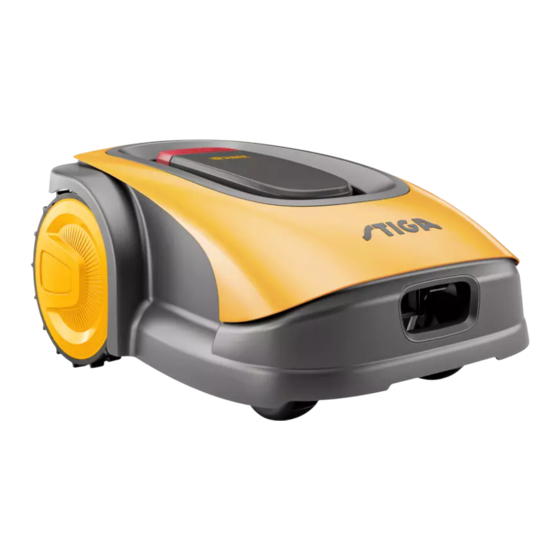
Stiga G 300 Instruction Manual
Hide thumbs Also See for G 300:
Table of Contents

Advertisement

Quick Links

G 300
G 600
G 1200
G 3600
EN
INSTRUCTION MANUAL

Advertisement

Table of Contents
loading

Summary of Contents for Stiga G 300

  • Page 1 G 300 G 600 G 1200 G 3600 INSTRUCTION MANUAL...
  • Page 2: Table Of Contents

    ENGLISH - TRANSLATION OF THE ORIGINAL INSTRUCTIONS TABLE OF CONTENTS 1. MODELS AND TECHNICAL DATA 1.1. MODELS ..............................1 1.2. TECHNICAL DATA ............................2 2. SAFETY 2.1. SAFETY INFORMATION ..........................4 2.2. SAFETY INSTRUCTIONS ........................... 6 2.2.1. SAFE OPERATING PROCEDURES ........................6 2.2.2. OPERATION ................................6 2.3. STOPPING AND TURNING OFF THE ROBOT LAWN MOWER IN SAFE CONDITIONS ......8 3.
  • Page 3 5.3.2. SAFE SHUTDOWN - SAFETY KEY ........................41 5.3.3. SWITCHING THE ROBT LAWN MOWER ON AND OFF - ON / OFF BUTTON ..........41 5.3.4. SCHEDULED PROGRAMME SELECTION / SINGLE WORK CYCLE / FORCED RETURN TO CHARGING BASE - MODE SELECTION BUTTON .......................... 42 5.3.5. BLUETOOTH STATUS DISPLAY - BLUETOOTH BUTTON ................44 ® ® 5.3.6. DISPLAY OF ALARM STATES-ALARM ICON ....................44 5.3.7. BATTERY CHARGE DISPLAY - BATTERY ICON ....................45 5.3.8. STARTING THE ROBOT LAWN MOWER ......................45 5.4. FUNCTIONING OF THE CHARGING BASE ..................... 46 5.5.
  • Page 5: Models And Technical Data

    1.1. MODELS This manual refers to the following models: G 300, G 600, G 1200 (TYPE: SRSW01) G 3600 (Type SRBW01) NOTE: the instructions in this manual apply to independent robot lawn mower models. All illustrations, unless otherwise indicated, refer to the SRSW01 platform.
  • Page 6: Technical Data

    Input: 100-240 Vac, 1.2 A; Output: 30 VDC, 2 A Input: 200-240 Vac, 0.8 A; Use one of the original codes below or subsequent updates Output: 30 VDC, 4 A (consult an authorised STIGA dealer) Use one of the original 118204158/0 (UE) codes below or subsequent...
  • Page 7 SPECIFICATIONS STIGA G 300 STIGA G 600 STIGA G 1200 STIGA G 3600 Use one of the original codes below or subsequent updates (consult an authorised STIGA 30 VDC extension cables dealer) permitted Code: 1127-0010-01, Length 5 m Code: 1127-0020-01, Length 15 m 25.2 - 25.9 V...
  • Page 8: Safety

    SAFETY 2.1. SAFETY INFORMATION In the design of the device, special attention has been paid to aspects that can cause risks to the safety and health of people. The purpose of this information is to sensitize users to prevent any risk, avoiding behaviours that do not comply with the regulations reported.
  • Page 9 CAUTION: Do not modify, tamper with, elude or eliminate the safety devices installed. WARNING: Check that there are no toys, tools, branches, clothing, or other items on the lawn that could damage the device. BAN: Do not sit on top of the robot lawn mower. BAN: Never lift the robot lawn mower to inspect the blade or to transport it when it's started.
  • Page 10: Safety Instructions

    2.2. SAFETY INSTRUCTIONS OBLIGATION: Read carefully before use and store for future reference. 2.2.1. SAFE OPERATING PROCEDURES Training a. Read the instructions carefully, learn the controls and the correct use of the machine. b. Never allow children, persons with reduced physical, sensory or mental capabilities, or lack of expe- rience and knowledge, or persons unfamiliar with these instructions, to operate the machine.
  • Page 11 Residual Risks - Although the product complies with all safety requirements, additional risks may still exist due to improper installation and/or unforeseeable circumstances. Therefore, the area on which the product will operate must be free of objects, people and animals, and all persons who may have access, even occasionally, to the work area must be informed of the possible hazards.
  • Page 12: Stopping And Turning Off The Robot Lawn Mower In Safe Conditions

    2.3. STOPPING AND TURNING OFF THE ROBOT LAWN MOWER IN SAFE CONDITIONS OBLIGATION: Always switch off the robot lawn mower in safe conditions before any cleaning, transport or maintenance operation. Requirements and obligations: • Safety key. Procedure: 1. Press the “STOP” (A) button to stop the robot lawn mower safely and open the protective cover (B). 2.
  • Page 13: Introduction

    INTRODUCTION 3.1. GENERAL INTRODUCTION 3.1.1. PURPOSE OF THE MANUAL This manual is an integral part of the device and it is intended to provide the information necessary for its use. Keep this manual for the entire life of the device, so that it is always available in case of need. The recipient of the manual is the user of the device, who is required to carefully read the information contained therein and apply it rigorously to protect people's safety and to avoid damage.
  • Page 14: Product Overview

    3.2. PRODUCT OVERVIEW 3.2.1. GENERAL DESCRIPTION The robot lawn mower (A) is designed and built to automatically cut garden grass at any time of day and night. According to the different characteristics of the surface to be cut, the lawnmower robot can be programmed to work on several areas delimited by the perimeter cable.
  • Page 15: Main Components

    3.2.2. MAIN COMPONENTS (A) Robot lawn mower (C1) Instruction manual (B) charging base (C2) charging base fixing screws (C) Starter kit (C3) Blister with blades and fixing screws (D) Battery/ies (inside the robot lawn mower) (C4) Charging Base connectors (E) charging base power supply (C5) App Lock Label (C6) Joint for perimeter cable (C7) Safety key...
  • Page 16: Unpacking

    • Installation kit (Optional for G 600. G 1200 and G 3600) (F) Perimeter cable (G) Perimeter cable fixing pegs (H) joint for perimeter cable (I) charging base connectors See Chapter 9 “Accessories” 3.3. UNPACKING Following are listed all the steps to perform the correct unpacking: 1.
  • Page 17: Symbols And Nameplates

    3.4. SYMBOLS AND NAMEPLATES Below all the symbols on the robot lawn mower are listed: WARNING: Read the user instructions before starting the product. WARNING: Danger of projections of objects against the body. Keep an adequate safe distance from the machine while it is running. WARNING: Do not put hands and feet near or under the opening of the cutting means.
  • Page 18 Symbols on model labels: Appliance with insulation class III, powered by battery (Robot Lawn mower) or special power supply unit (Charging Base and Reference Station). Use the original power supply with the specifications on the rating plate. DC power supply symbol. Protection rating against the ingress of solids and water. Electrical and Electronic Equipment Waste, to be taken to designated facilities for recycling and disposal.
  • Page 19: General Manual Reading Instructions

    3.5. GENERAL MANUAL READING INSTRUCTIONS The criteria used for the preparation of this document are described below. 1. Topic title (A). 2. Requirements and equipment for carrying out the procedure (B). 3. Description of the procedure (C). 4. Descriptive pictures of the procedure (D). 5.
  • Page 20: Installation

    4.1. GENERAL INSTALLATION INFORMATION CAUTION: Do not modify, tamper with, elude or eliminate the safety devices installed. NOTE: For further clarification on the installation of the product please contact a STIGA dealer. 4.2. INSTALLATION COMPONENTS (A) Charging base (B) Power supply...
  • Page 21: Verification Of The Installation Requirements

    4.3. VERIFICATION OF THE INSTALLATION REQUIREMENTS Below, the procedures to check the necessary requirements and prepare the garden before proceeding with the installation are described. 4.3.1. GARDEN VERIFICATION: • Carry out a survey of the entire area for a correct detection of the state of the garden, of any obstacles and areas to be excluded.
  • Page 22 WARNING: The power cable (C), power supply unit, extension cord and all other electric cables which do not belong to the product must remain outside the cutting area to maintain their distance from hazardous moving parts and prevent damage to cables which may come into contact with live parts. 3. Make sure that the area chosen for installing the charging base (D) is at least 400 cm away from the charging base (E) of a possible second robot lawn mower.
  • Page 23: Main Checks When Installing The Perimeter Cable

    4.3.3. MAIN CHECKS WHEN INSTALLING THE PERIMETER CABLE: 1. Check that the maximum slope of the work area is less than or equal to 45% or 50% depending on the model (see Par. 1.2 TECHNICAL DATA), and comply with the rules shown in Fig. below a) if the slope is ≤...
  • Page 24 WARNING: The robot can mow surfaces with a maximum slope of 45% or 50% depending on the model. In case of non-compliance with the instructions, the robot may slip and exit the work area WARNING: Areas with slopes greater than those permissible may not be mowed Place the perimeter cable before the slope excluding that area of the lawn from being mowed.
  • Page 25: Criteria For Installing The Perimeter Cable

    STRUCTURAL ELEMENT TYPE SRSW01 SRBW01 MODEL G 300, G 600, G 1200 G 3600 If there is a pavement or path (A) at the same X1= 5cm level as the lawn, arrange the perimeter cable (B) at X1 distance of...
  • Page 26 4. INSTALLATION...
  • Page 27 WARNING: If the slope is greater than 45% or 50%, depending on the model, the slope area must be excluded from the cutting area (See Par. 4.3). CAUTION: The operating area and more generally the area in which the robot lawn mower can travel must be cordoned off by fencing.
  • Page 28: Delimitation Of Obstacles

    X-PASSAGE BETWEEN TWO DIFFERENT SECTIONS OF PERIMETER CABLE TYPE SRSW01 SRBW01 MODEL G 300, G 600, G 1200 G 3600 The obstacle can be delimited by overlapping the outward and X>= 70cm (Q) X>= 90cm (Q) return cable sections without crossing them (Q), (R).
  • Page 29: Passages Among Different Areas Of The Garden

    TRANSITIONS BETWEEN DIFFERENT AREAS OF THE GARDEN CORRIDOR WIDTH Z TYPE SRSW01 SRBW01 MODEL G 300, G 600, G 1200 G 3600 Zone (A) can be reached by the robot lawn mower Z >= 70 cm Z > = 90 cm authomatically.
  • Page 30: Installation Of The Perimeter Cable

    Country where it is used. 4.5.1. INSTALLATION OF THE PERIMETER CABLE MAXIMUM LENGTH OF STIGA CABLES COMPATIBLE WITH THE INSTALLATION PERIMETER CABLE Code 1127-0000-01 Reel 150 m, Ø 2.7 mm Code 1127-0001-01 Reel 300 m, Ø...
  • Page 31 Make sure that the cable is in contact with the ground along its path to prevent the robot lawn mower from damaging it. POSITIONING UNDERGROUND (CARRIED OUT ONLY BY AUTHORIZED RETAILER) Turning to a STIGA retailer, the perimeter cable can also be installed using a specific wire-laying machine, without using pegs. 4. INSTALLATION...
  • Page 32: Junction Of The Perimeter Cable

    4.5.2. JUNCTION OF THE PERIMETER CABLE. CAUTION: CAUTION: Danger of cutting hands. Danger of dust in the eyes. Requirements and obligations: • Joint for perimeter cable • Gloves • Electrician's scissors • Glasses • Pliers GLOVES OBLIGATION: GLASSES OBLIGATION: Use protective gloves to avoid Use safety glasses to avoid the cutting your hands.
  • Page 33: Installation Of The Charging Base

    4.5.3. INSTALLATION OF THE CHARGING BASE CAUTION: CAUTION: Danger of cutting hands. Danger of dust in the eyes. ELECTRICAL HAZARD: Connect the power supply only at the end of all the installation operations. If necessary during the installation, turn off the general power supply. Requirements and obligations: •...
  • Page 34 4. Install the charging base aligned with the perimeter cable (D2) so that the robot will be able to access it by navigating the perimeter cable clockwise. 5. Insert the two ends of the cable into the appropriate slots (E2). 6.
  • Page 35: Resistor Installation For Small Perimeters

    WARNING: The power cable, power supply unit, extension cord and all other electric cables which do not belong to the product must remain outside the cutting area to maintain their distance from hazardous moving parts and prevent damage to cables which may come into contact with live parts. NOTE: If necessary, it is possible to extend the power cable to the charging base by using the extension cables.
  • Page 36: Charging The Robot Lawn Mower After Installation

    4.6. CHARGING THE ROBOT LAWN MOWER AFTER INSTALLATION Requirements and obligations: • Charging base. Procedure: 1. Recharge the robot lawn mower (See Par 5.5). NOTE: When charged for the first time, the batteries must remain connected for at least 2 hours. 4.
  • Page 37: Product Settings

    The automatic operation of the robot lawn mower requires a series of settings that can be made via mobile device (smart phone) iOS or Android with the "STIGA GO" App installed. The iOS app is downloadable from the iOS App Store. The Android app is downloadable from the Google Play Store.
  • Page 38: Prelogin

    The robot lawn mower is equipped with a 3G/4G connectivity module with SIM card that allows connection to the STIGA cloud and remote control of the robot lawn mower. After linking the device with the user account, the SIM card must be activated.
  • Page 39: Closed Area

    4.7.6. CLOSED AREA NOTE: Check the availability of this function on the STIGA.GO App. The "Closed Area" section allows to start the robot lawn mower in an enclosed area normally excluded from the work area because it is not reachable, but in any case delimited by the perimeter cable. (See Par.
  • Page 40: Border Cut

    4.7.12. ECO MODE NOTE: Check the availability of this function on the STIGA.GO App. The 'Eco mode' function allows the user to set a low-energy mode by proportionally reducing the working time of the robot lawn mower compared to the time programmed by the user.
  • Page 41: Integration With Voice Assistants (Amazon Alexa, Google Home) (Depending On The Model)

    • Ask about the next scheduled start time. • Ask about the robot lawn mower's status. NOTE: integration of the robot lawn mower with a voice assistant is not done via the Stiga.GO app, but must be set up via the voice assistant app itself.
  • Page 42: Operation

    OPERATION Requirements and obligations: • Installation completed according to • Programming the robot lawn mower instructions (See Ch. 4) according to the instructions (See Par. 4.7 for automatic function) • Powered charging base • Initial grass height in the range of operation of the robot lawn mower: 20-60 mm •...
  • Page 43: Manual Functioning Of The Robot Lawn Mower

    5.2. MANUAL FUNCTIONING OF THE ROBOT LAWN MOWER The robot lawn mower can be used without performing the programming procedure described in Par. 4.7. In this mode the robot lawn mower carries out a work cycle, returns to the charging base and remains there until the next manual start.
  • Page 44: Description Of The Controls On The Robot Lawn Mower

    5.3. DESCRIPTION OF THE CONTROLS ON THE ROBOT LAWN MOWER List of controls, indicators and their function: • The “STOP” button (A): is used to safely stop the robot mower. • The “SAFETY KEY” (D): is used for the safety shut-down of the robot lawn mower. •...
  • Page 45: Safe Shutdown - Safety Key

    5.3.2. SAFE SHUTDOWN - SAFETY KEY The safety key (D), by switching off, allows the robot lawn mower to be switched off safely. OBLIGATION: Always remove the safety key before any operation of cutting height adjustment, cleaning, transport and maintenance Procedure: 1. Press the “STOP” button (A) to open the cover (B) and access the control panel (C). 2.
  • Page 46: Scheduled Programme Selection / Single Work Cycle / Forced Return To Charging Base - Mode Selection Button

    5.3.4. SCHEDULED PROGRAMME SELECTION / SINGLE WORK CYCLE / FORCED RETURN TO CHARGING BASE - MODE SELECTION BUTTON The "MODE SELECTION" button is used to activate or deactivate the set work program via the App and to select the forced return to the charging base. The robot lawn mower operates according to the possible selections described below.
  • Page 47 Procedure: 1. Press the “STOP” button (A) to open the cover (B) and access the control console (C). 2. Press the “MODE SELECT” button (F) until the icons of the functions you wish to activate flash. The icons relating to the selected functions flash. 3.
  • Page 48: Bluetooth ® Status Display - Bluetooth ® Button

    5.3.5. BLUETOOTH STATUS DISPLAY - BLUETOOTH BUTTON ® ® The robot lawn mower handles automatically the Bluetooth connection with external mobile devices. The ® Bluetooth connection is available at all times when the robot lawn mower is switched on. It is possible to ®...
  • Page 49: Battery Charge Display - Battery Icon

    5.3.7. BATTERY CHARGE DISPLAY - BATTERY ICON The “BATTERY” light icon (O) indicates the battery charge status. Procedure: 1. Press the “STOP” button (A) to open the cover (B) and access the control panel (C). 2. Check the battery charging status through the light icon (O): - Blue icon: the battery is charged (charge level >40 %).
  • Page 50: Functioning Of The Charging Base

    5.4. FUNCTIONING OF THE CHARGING BASE The charging base is equipped with an indicator light (N) that lights up in the following manner: • Warning light off: the charging base is powered off or the robot is on the base; •...
  • Page 51: Cutting Height Adjustment

    10mm. Lower the cutting height further only after the garden has been mowed evenly. Procedure (TYPE: SRSW01 - MODEL G 300, G 600, G 1200). MANUAL ADJUSTMENT: 1. Press the “STOP” button (A) to open the cover (B) and access the control panel (C).
  • Page 52 Procedure (TYPE SRBW01 - MODEL G 3600). ELECTRICAL ADJUSTMENT 1. Follow APP wizard to adjust the cutting height. NOTE: The blade height adjustment system requires an initial calibration and subsequent periodic calibrations, which are performed automatically. Calibration can also be performed manually using the dedicated menu in the App.
  • Page 53: Maintenance

    MAINTENANCE 6.1. SCHEDULED MAINTENANCE CAUTION: CAUTION: Only use original spare parts. Do not modify, tamper with, elude or eliminate the safety devices installed. For a better operation and longer life, be sure to clean the product regularly and replace worn parts. Perform the interventions following the frequency indicated in the table.
  • Page 54: Product Cleaning

    6.2. PRODUCT CLEANING CAUTION: CAUTION: Danger of cutting hands. Danger of dust in the eyes. Requirements and obligations: • Sponge • Dry cloth • Neutral soap • Gloves • Brush • Glasses • Water GLOVES OBLIGATION: GLASSES OBLIGATION: Use protective gloves to avoid Use safety glasses to avoid the cutting your hands.
  • Page 55 BAN: To avoid irreversible damage to the electrical and electronic components, do not immerse the robot lawn mower, partially or completely, in water. BAN: Do not wash the internal parts of the robot lawn mower to avoid damaging the electrical and electronic components. BAN: Do not use solvents or petrol so as not to damage varnished surfaces and plastic parts.
  • Page 56: Replacement Of The Cutting Blades

    3. Turn the robot lawn mower upside down, taking care in not to damage the floating cover. 4. Unscrew the fixing screws (E). 5. Replace the cutting blades (D). 6. Unscrew the fixing screws (E). G 300, G 600, G 1200 G 3600 (TYPE SRSW01) (TYPE SRBW01)
  • Page 57: Winter Battery Maintenance And Storage

    NOTE: The battery must be recharged every 6 months and, in any case, before winter storage. 6.5. BATTERY REPLACEMENT Battery replacement is the sole responsibility of the STIGA TECHNICAL ASSISTANCE STAFF. If the battery needs to be replaced, contact a service centre or your retailer. 6. MAINTENANCE...
  • Page 58: Troubleshooting

    TROUBLESHOOTING CAUTION: Stop the robot lawn mower and bring it back to safety conditions (See Par. 5.3.2). Below there is the list of any anomalies that may arise during the work phase. PROBLEM CAUSES SOLUTIONS Damaged cutting disc or blades. Replace the damaged components (See Par.
  • Page 59 PROBLEM CAUSES SOLUTIONS The charging base light The supply voltage is missing Check that the power supply unit is does not turn on when or there is a fault in the charging plugged in correctly. Check the integrity of the robot is out of the base.
  • Page 60: Transport, Storage And Disposal

    TRANSPORT, STORAGE AND DISPOSAL 8.1. TRANSPORT Procedure: NOTE: We recommend using the original packaging for transport over long distances. 1. Press the “STOP” (A) button to stop the robot lawn mower and open the protective cover (B). 2. Switch off the robot lawn mower in safety conditions (see par. 2.3). 3.
  • Page 61: Accessories

    ACCESSORIES Art. number Description Specifications 1127-0009-01 Cutting blades 12 pcs 1127-0011-01 Charging base cover - for For additional protection against rain and platform TYPE: SRSW01 sunlight 1127-0024-01 Charging base cover - for For additional protection against rain and platform TYPE: SRBW01 sunlight.
  • Page 62: Warranty

    REGISTERED TRADEMARKS AND LICENCES The name and logo Bluetooth are registered trademarks owned by Bluetooth SIG, inc. and any use made ® of such marks by STIGA is under license. 10. WARRANTY...
  • Page 63: Ec Declaration Of Conformity

    Ampiezza di taglio: 18 cm n) Persona autorizzata a costituire il Fascicolo Tecnico: ST. S.p.A. Via del Lavoro, 6 31033 Castelfranco Veneto (TV) - Italia o) Castelfranco Veneto, 10/02/2024 CEO Stiga Group Sean Robinson 171514280/2 11. EC DECLARATION OF CONFORMITY...
  • Page 64 ETSI EN 303 413 V1.1.1 i) Ampiezza di taglio: 26 cm n) Persona autorizzata a costituire il Fascicolo ST. S.p.A. Tecnico: Via del Lavoro, 6 31033 Castelfranco Veneto (TV) - Italia CEO Stiga Group o) Castelfranco Veneto, 10/02/2024 Sean Robinson 171514286/0 11. WARRANTY...
  • Page 65 STIGA S.p.A. STIGA LTD (UK Importer) Via del lavoro, 6 Unit 8, Bluewater Estate Plympton, Devon, PL7 4JH, England 31033 Castelfranco Veneto (TV) Italy stiga.com...

This manual is also suitable for:

G 600G 1200G 3600

Table of Contents