HIKVISION DS-KH6320-WTDE1 User Manual
Video intercom kit
Hide thumbs
Also See for DS-KH6320-WTDE1:
- Manual (2 pages) ,
- Configuration manual (69 pages) ,
- Quick start manual (2 pages)
Table of Contents
Advertisement
Advertisement
Table of Contents

Related Manuals for HIKVISION DS-KH6320-WTDE1


Summary of Contents for HIKVISION DS-KH6320-WTDE1
- Page 1 Video Intercom Kit User Manual...
- Page 2 WITHOUT LIMITATION, MERCHANTABILITY, SATISFACTORY QUALITY, OR FITNESS FOR A PARTICULAR PURPOSE. THE USE OF THE PRODUCT BY YOU IS AT YOUR OWN RISK. IN NO EVENT WILL HIKVISION BE LIABLE TO YOU FOR ANY SPECIAL, CONSEQUENTIAL, INCIDENTAL, OR INDIRECT DAMAGES,...
- Page 3 During the use of device, personal data will be collected, stored and processed. To protect data, the development of Hikvision devices incorporates privacy by design principles. For example, for device with facial recognition features, biometrics data is stored in your device with encryption method;...
- Page 4 Video Intercom Kit User Manual Symbol Conventions The symbols that may be found in this document are defined as follows. Symbol Description Indicates a hazardous situation which, if not avoided, will or could Danger result in death or serious injury. Indicates a potentially hazardous situation which, if not avoided, could Caution result in equipment damage, data loss, performance degradation, or...
- Page 5 Video Intercom Kit User Manual Safety Instruction Warning All the electronic operation should be strictly compliance with the electrical safety regulations, ● fire prevention regulations and other related regulations in your local region. Please use the power adapter, which is provided by normal company. The power consumption ●...
- Page 6 Video Intercom Kit User Manual Improper use or replacement of the battery may result in hazard of explosion. Replace with the ● same or equivalent type only. Dispose of used batteries according to the instructions provided by the battery manufacturer. Input voltage should meet both the SELV and the Limited Power Source according to 60950-1 ●...
- Page 7 Video Intercom Kit User Manual Regulatory Information EU Conformity Statement This product and - if applicable - the supplied accessories too are marked with "CE" and comply therefore with the applicable harmonized European standards listed under the EMC Directive 2014/30/EU, RE Directive 2014/53/EU,the RoHS Directive 2011/65/EU 2012/19/EU (WEEE directive): Products marked with this symbol cannot be disposed of as unsorted municipal waste in the European Union.
- Page 8 Video Intercom Kit User Manual Conformément à la réglementation d'Industrie Canada, le présent émetteur radio peut fonctionner avec une antenne d'un type et d'un gain maximal (ou inférieur) approuvé pour l'émetteur par Industrie Canada. Dans le but de réduire les risques de brouillage radioélectrique à l'intention des autres utilisateurs, il faut choisir le type d'antenne et son gain de sorte que la puissance isotrope rayonnée équivalente (p.i.r.e.) ne dépasse pas l'intensité...
-
Page 9: Table Of Contents
Video Intercom Kit User Manual Contents Chapter 1 About this Manual ...................... 1 Chapter 2 Introduction ....................... 2 Chapter 3 Appearance ........................ 3 Chapter 4 Terminal and Wiring Description ................. 5 4.1 Terminal Description ......................5 4.2 Wiring Description ......................... 9 Chapter 5 Installation ....................... - Page 10 Video Intercom Kit User Manual 8.1.1 Call Settings ......................... 46 8.1.2 Leave Message ......................49 8.1.3 Live View ........................49 8.1.4 Arm/Disarm ........................ 51 8.1.5 Call Elevator ........................ 53 8.1.6 Relay Settings ......................54 8.1.7 Information Management ................... 54 Appendix A. Cables ........................56...
-
Page 11: Chapter 1 About This Manual
Video Intercom Kit User Manual Chapter 1 About this Manual Get the manual and related software from or the official website (http://www.hikvision.com). Product Model Network Indoor Station DS-KH6320-WTDE1 Doorphone DS-KB2421T-IM... -
Page 12: Chapter 2 Introduction
Video Intercom Kit User Manual Chapter 2 Introduction Features of the hybrid video intercom products: User-friendly control with a convenient touch screen. ● Convenient management via the Hik-Connect mobile client. ● More cost-effective options with analog doorbells. ● Easy installation as the doorbell requires no exclusive power supply. ●... -
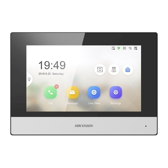
Page 13: Chapter 3 Appearance
Video Intercom Kit User Manual Chapter 3 Appearance Network Indoor Station Figure 3-1 Appearance of Indoor Station Table 3-1 Description Description Screen Microphone SD Card Slot Four-Wire Terminals Network Interface Power Supply Interface Alarm Input/Relay Output/RS-485 Interface Serial Port (For Debugging Use Only) - Page 14 Video Intercom Kit User Manual Doorphone Figure 3-2 Appearance of Doorphone Table 3-2 Description Description Microphone Built-in Camera Call Button Loud Speaker...
-
Page 15: Chapter 4 Terminal And Wiring Description
Video Intercom Kit User Manual Chapter 4 Terminal and Wiring Description 4.1 Terminal Description Note You can refer to Appendix for more details about cable specification. Network Indoor Station Wiring Figure 4-1 Terminal of Indoor Station... - Page 16 Video Intercom Kit User Manual Table 4-1 Descriptions of Terminal and Interfaces Interface Description Function 12 VDC Power For the connection of doorphone 1 supply for doorphone 1 Video input of doorphone 1 Audio input/ output of doorphone 1 Grounding 12 VDC Power For the connection of doorphone 2 supply for...
- Page 17 Video Intercom Kit User Manual Interface Description Function 485+ RS-485+ Interface For the connection of devices via RS-485 485- RS-485- Interface...
- Page 18 Video Intercom Kit User Manual Doorphone Wiring Figure 4-2 Terminal of Doorphone...
-
Page 19: Wiring Description
Video Intercom Kit User Manual Table 4-2 Descriptions of Terminal and Interfaces Interface Description Function 5V: Power Supply For the connection of indoor station (from Indoor Station) CVBS: Video Output AUDIO: Audio Input/Output GND: Grounding Signal NO: Door Lock For the connection of door lock Relay Output/ Normally Open COM: Door Lock... - Page 20 Video Intercom Kit User Manual Typical Application Figure 4-3 Topology Note Network indoor station can be connected to LAN(PoE) with Network Cable. ●...
-
Page 21: Chapter 5 Installation
Video Intercom Kit User Manual Chapter 5 Installation 5.1 Install Indoor Station 5.1.1 Wall Mounting with Junction Box Before You Start Note Make sure the device in the package is in good condition and all the assembly parts are included. ●... -
Page 22: Mounting Indoor Station Without Junction Box
Video Intercom Kit User Manual Figure 5-2 Wall Mounting with Junction Box 5.1.2 Mounting Indoor Station without Junction Box Before You Start Note Make sure the device in the package is in good condition and all the assembly parts are included. ●... -
Page 23: Install Doorbell
Video Intercom Kit User Manual Figure 5-3 Wall Mounting without Junction Box 5.2 Install Doorbell Before You Start Make sure you have powered off the main power switch of your home. ● Make sure you have connected power cables of the doorbell. ●... - Page 24 Video Intercom Kit User Manual Figure 5-4 Wall Mounting Plate Steps 1. Fix the wall mounting shield to the wall with 2 screws. 2. Hook the door station to the shield tightly by inserting the hooks of shield panel into the slots on the rear panel of the door station.
- Page 25 Video Intercom Kit User Manual Figure 5-5 Wall Mounting...
-
Page 26: Chapter 6 Activation
Video Intercom Kit User Manual Chapter 6 Activation 6.1 Activate Indoor Station You can configure and operate the indoor station after creating a password for the device activation. Steps 1. Power on the device. It will enter the activation page. Figure 6-1 Activation Page 2. -
Page 27: Chapter 7 Configuration
Video Intercom Kit User Manual Chapter 7 Configuration 7.1 Local Operation 7.1.1 Quick Operation After device activation, the wizard page will pop up. The description is for other indoor stations. Steps 1. Choose language and tap Next. Figure 7-1 Language Settings 2. - Page 28 Video Intercom Kit User Manual Figure 7-2 Password Reset Methods 3. Set network parameters and tap Next. - Edit Local IP, Subnet Mask and Gateway parameters manually. - Enable Auto Get IP address, the device will get network parameters automatically. Figure 7-3 Network Parameters...
- Page 29 Video Intercom Kit User Manual 4. Configure the indoor station. 1) Select Device Type as Indoor Station or Indoor Extension. 2) Set Floor No.. 3) Set Room No.. 4) Configure advanced settings. Set Comminity No., Building No. and Unit No. 5) Set Registration Password.
- Page 30 Video Intercom Kit User Manual Figure 7-5 Wi-Fi 6. Set time and tap Next. Note The time can be synchronized to door stations. 1) Select the Time Zone. 2) Tap Date Format and Time Format to set the time format. 3) Tap Time to set time manually.
- Page 31 Video Intercom Kit User Manual Figure 7-6 Time Settings 7. Configure the Hik-Connect service settings. 1) Enable Hik-Connect service. 2) Edit verification code or use the activation password by default. 3) View Hik-Connect Server Status. 4) Scan the first QR Code to download the APP of Hik-Connect. Scan the second QR Code to add your device to the APP.
- Page 32 Video Intercom Kit User Manual Figure 7-7 Hik-Connect Service Settings 8. Link related devices and tap Next. If the device and the indoor station are in the same LAN, the device will be displayed in the list. Figure 7-8 Related Device 1) Tap the door station in the list to link.
-
Page 33: Basic Settings
Video Intercom Kit User Manual Note If the door station is inactive, the system will pop up the dialog to activate the door station. 2) Edit the network parameters of the door station manually. 3) Tap Next. 9. Optional: Enable Indoor Station and link related indoor extension devices. Tap Finish. If the indoor extension and the indoor station are in the same LAN, the device will be displayed in the list. - Page 34 Video Intercom Kit User Manual Set Indoor Station Network Parameters Network connection is mandatory for the use of the indoor station. Set the network parameters after activating the indoor station. Only when the IP address of the indoor station is in the same network segment as other devices, it can work properly in the same system.
- Page 35 Video Intercom Kit User Manual Tap Settings → . Enable Wi-Fi, and the indoor station will search available Wi-Fi automatically. Note The Wi-Fi IP can be changed. Figure 7-11 Wi-Fi Settings Select an Wi-Fi and connect. Set Linked Device IP Linked network parameters refers to the network parameters of devices (like door station, doorphone, main station, center, etc.), to which the indoor station is linked.
- Page 36 Video Intercom Kit User Manual Note Default admin password is the activation password. 2. Tap Main Door Station to pop up the device information dialog. Figure 7-13 Device Information Set the parameters of the linked door station. Tap to set parameters of the door station. 3.
- Page 37 Video Intercom Kit User Manual Volume Settings Set microphone volume and output volume. Call Number Settings The call No. should be the same as the indoor station's room No. If press the call button of the door station, you can call the indoor station directly. Public Password You can use the public password to open the door station related door lock.
- Page 38 Video Intercom Kit User Manual Figure 7-14 Set Indoor Station No. 2. Select Indoor Station to set the room information, live view duration, SIP parameters and password. Room Information You can set room name, floor No., and room No. Tap Advanced Settings to set community No., building No.
- Page 39 Video Intercom Kit User Manual Room Information You can set room name and No. Tap Advanced to set the community No., building No., and unit No. if you need. When calling the indoor station and the two devices are in the same building, you can call the room No.
- Page 40 Video Intercom Kit User Manual Figure 7-15 Analog Doorphone Note The unlock time is between 1 s to 255 s. Add Camera Steps 1. Tap Settings → → Configuration , and enter admin (activation) password. 2. Tap to enter the device management page. 3.
- Page 41 Video Intercom Kit User Manual SIP Settings Devices can communicate with each other via SIP protocol. You create set the SIP register password, enable standard SIP and set VOIP account. Steps 1. Tap Settings → → Configuration , and enter admin (activation) password. 2.
- Page 42 Video Intercom Kit User Manual Figure 7-17 VOIP Account Settings Note Up to 32 characters are allowed in the user name. Zone and Alarm Settings Zone Settings You can set the zone type, alarm type and delay time and other parameters of 2 zones. Before You Start Tap Settings →...
- Page 43 Video Intercom Kit User Manual Figure 7-18 Zone Settings 2. Press a zone to pop up the zone editing dialogue box. 3. Set the zone type, alarm type, status of arming status, entering delay, and exiting delay. 4. Tap OK to save the settings. Note 2 zone types are selectable: Smoke Detector and Gas Detector.
-
Page 44: Password Settings
Video Intercom Kit User Manual 2. Tap Stay Mode, Away Mode, Sleeping Mode, or Custom to enter the page. 3. Arm the selected zone. Note Zones are configurable on the arming mode page. ● Smoke detector zone and gas detector zone will be triggered even if they are disabled. ●... - Page 45 Video Intercom Kit User Manual 5) Tap OK. 4. Create a new password and confirm it. 5. Tap OK. Change by Security Question You can change admin password via security questions. Before You Start You need to security questions at the wizard or tap Settings → →...
-
Page 46: Synchronize Time
Video Intercom Kit User Manual Duress Code When you are hijacked and forced to open the door, you can enter the duress code. An alarm will be triggered to notify the management center secretly. Note The duress code and the unlock password cannot be the same. 4. -
Page 47: Sound Settings
Video Intercom Kit User Manual Figure 7-19 Time Synchronization 1) Select the Time Zone. 2) Enable Enable NTP. 3) Set the synchronizing interval, enter the IP address/domain of NTP server and port No. Note The default unit of synchronizing interval is minute. ●... - Page 48 Video Intercom Kit User Manual Figure 7-20 Call Settings 2. Set corresponding parameters. Ringtone There are 3 ringtones by default, and you can custom and import at most 4 ringtones via Batch Configuration Tool or iVMS-4200 Client Software. Ringtone Duration: The maximum duration of indoor station when it is called without being accepted.
- Page 49 Video Intercom Kit User Manual Figure 7-21 Main Page Note Before enabling Auto-answer, the function of Leave Message needs to be enabled. Tap Settings → → to enter the shortcut settings page. Eanble Leave Message and go back to calling settings page to enable Auto-answer. Do Not Disturb Device Select All and all devices will not disturb this device.
-
Page 50: Link To The Mobile Client
Video Intercom Kit User Manual Steps 1. Tap Settings → → Volume Settings to enter the volume settings page. Figure 7-22 Volume Settings Page 2. Set the microphone volume, prompt sound volume, and the call volume of the indoor station. Set the microphone volume and speaker volume for analog doorphone. -
Page 51: System Settings
Video Intercom Kit User Manual Figure 7-23 Enable Guarding Vision Service 3. Edit LBS server and Verification Code. Note Verification code is used to add the device to mobile client. 4. Optional: Scan the QR code on the screen. Note Scan the left QR code on the screen to access Hik-Connect. - Page 52 Video Intercom Kit User Manual Figure 7-24 General Settings Page Password You can manage your arm/disarm password and scene password. For details, see Modify Arm/ Disarm Password Time and Date You can set the displayed time and date format, current time. You can also tap Sync Time and enable NTP to synchronize the device time.
- Page 53 Video Intercom Kit User Manual Note After enabling Clear Screen function, press and hold the Unlock key to exit the clear screen ● mode. The device without unlock key will exit the clear screen mode automatically when the time is ●...
-
Page 54: Output Settings
Video Intercom Kit User Manual Preference You can configure zone settings, scene settings and shortcut settings on the preference page. Tap Settings → to enter the preference page. Zone Settings Note Only when enable Alarm in the shortcut settings, can the Zone Settings displayed on the Preference page. -
Page 55: Device Information
Video Intercom Kit User Manual Note 1 to 32 characters are allowed. Supports uppercase letters, lowercase letters, numerics, and special characters. Remain Open Enable the function, the relay remains open. Disabled the function, and you can set the remain open duration. Note By default, the function is disabled. -
Page 56: Chapter 8 Operation
Video Intercom Kit User Manual Chapter 8 Operation 8.1 Local Operation 8.1.1 Call Settings Add Contact Steps 1. Tap Call → to enter the contact list page. Figure 8-1 Contact List 2. Tap to pop up the contact adding dialog. 3. - Page 57 Video Intercom Kit User Manual Call Resident Steps 1. Tap Call → to enter the residents calling page. Figure 8-2 Call Resident 2. Enter the calling number. The calling number format should be x-x-x-xxx. For example, the calling number of Community 1, Building 2, Unit 3, and Room 405 is 1-2-3-405.
- Page 58 Video Intercom Kit User Manual Receive Call The indoor station and indoor extension can receive calls from the analog doorphone, the door station, the main station or iVMS-4200 Client. On the call from door station page, there are 2 unlock buttons: Unlock 1, and Unlock 2. When you tap Unlock 1, the building gate will open by default, and when you tap Unlock 2, the door connected to the door station with the secure control door unit will open.
-
Page 59: Leave Message
Video Intercom Kit User Manual 2. Tap a piece of call logs in the list to call back. Note The indoor station saves call logs from analog doorphones, door stations, outer door stations, ● management center and other indoor stations. Hold a piece of call logs to open the call logs handling menu. - Page 60 Video Intercom Kit User Manual Figure 8-4 Live View...
-
Page 61: Arm/Disarm
Video Intercom Kit User Manual Note The indoor extension can connect to indoor station with network cables. After connecting, the ● indoor extension can view related devices that linked to the indoor station. The indoor extension can link to analog doorphones independently and view linked ●... - Page 62 Video Intercom Kit User Manual Figure 8-5 Arm Settings page 2. Select Stay, Away, Sleeping or Custom. 3. Enter the arm/disarm password to enable the scene. Note You can set the arm/disarm password in the general settings. For details, see the configuration guide.
-
Page 63: Call Elevator
Video Intercom Kit User Manual Figure 8-6 Disarm Room 2. Enter the arm/disarm password. Note You can set the arm/disarm password in the general settings. For details, see the configuration guide. 3. Tap OK. 8.1.5 Call Elevator The indoor station supports calling the elevator. Before You Start Enable call elevator via iVMS-4200 Client Software. -
Page 64: Relay Settings
Video Intercom Kit User Manual Figure 8-7 Call Elevator 2. Tap on the home page of the indoor station to start calling the elevator. 3. When the device communicates with door station, tap unlock icon to start calling the elevator. 8.1.6 Relay Settings After you set the output parameters and display the relay button on the main page, you can control the relay manually. - Page 65 Video Intercom Kit User Manual Figure 8-8 Alarm Logs Delete a Log: Hold the item, you can delete it. Clear Logs: Hold the item, you can clear all logs. See Details: Hold a alarm log, you can see the alarm details. Note Indoor extension only supports alarm log and capture log.
-
Page 66: Appendix A. Cables
Video Intercom Kit User Manual Appendix A. Cables Cables and Wiring When there are multiple cores in one parallel line, only one pair of closed cores are allowed to ● transmit signal. It is not allowed to use multiple pair of cores in one cable to transmit signal. When using parallel lines, it is suggested to use those with shielding layer. - Page 67 UD34408B...
Need help?
Do you have a question about the DS-KH6320-WTDE1 and is the answer not in the manual?
Questions and answers