Table of Contents
Advertisement
Advertisement
Table of Contents

Related Manuals for HIKVISION KB8113


Summary of Contents for HIKVISION KB8113
- Page 1 KB8113 Vandal-Resistant Video Intercom Doorbell User Manual...
- Page 2 MERCHANTABILITY, SATISFACTORY QUALITY, OR FITNESS FOR A PARTICULAR PURPOSE. THE USE OF THE PRODUCT BY YOU IS AT YOUR OWN RISK. IN NO EVENT WILL HIKVISION BE LIABLE TO YOU FOR ANY SPECIAL, CONSEQUENTIAL, INCIDENTAL, OR INDIRECT DAMAGES, INCLUDING, AMONG OTHERS, DAMAGES FOR LOSS...
- Page 3 During the use of device, personal data will be collected, stored, and processed. To protect data, the development of Hikvision devices incorporates privacy by design principles. For example, for devices with facial recognition features, biometrics data is stored in your device with encryption method;...
- Page 4 KB8113 Vandal-Resistant Video Intercom Doorbell User Manual Caution • Do not drop the device or subject it to physical shock, and do not expose it to high electromagnetism radiation. Avoid installing the equipment on vibrating surfaces or places subject to shock (ignoring this can cause equipment damage).
- Page 5 KB8113 Vandal-Resistant Video Intercom Doorbell User Manual Regulatory Information FCC Information Please take attention that changes or modification not expressly approved by the party responsible for compliance could void the user’s authority to operate the equipment. FCC Compliance: This equipment has been tested and found to comply with the limits for a Class B digital device, pursuant to part 15 of the FCC Rules.
- Page 6 KB8113 Vandal-Resistant Video Intercom Doorbell User Manual 2006/66/EC (Battery Directive): This product contains a battery that cannot be disposed of as unsorted municipal waste in the European Union. See the product documentation for specific battery information. The battery is marked with this symbol, which may include lettering to indicate cadmium (Cd), lead (Pb), or mercury (Hg).
-
Page 7: Table Of Contents
KB8113 Vandal-Resistant Video Intercom Doorbell User Manual Contents Appearance ..........................1 Terminal and Wiring Description ....................2 2.1 Terminal Description ........................2 2.2 Wiring Description ........................2 Doorbell Installation ........................5 3.1 Wall Mounting Plate ........................5 3.2 Wall Mounting ..........................5 Activate Device via over the Web .................... -
Page 8: Appearance
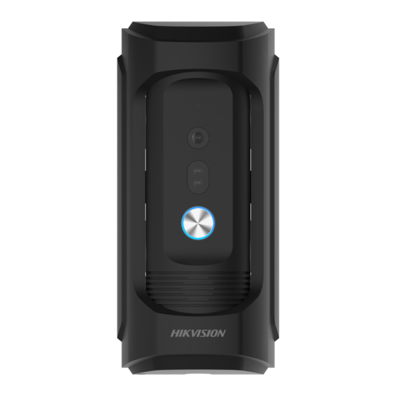
KB88113 Vandal-Resistant Video Intercom Doorbell User Manual 1.0 Appearance Figure 1-1 Appearance Table 1-1 Component Description No. Description Microphone Built-in Camera Low Illumination Supplement Light Call Button Loudspeaker UM KB8113 Doorbell 021821NA... -
Page 9: Terminal And Wiring Description
Door Lock Relay Output (Connect Electric Bolt or Contact Lock) 2.2 Wiring Description 2.2.1 Door Lock Wiring Terminal NC/COM is set as default for connecting magnetic lock/electric bolt; terminal NO/COM is set as default for connecting electric strike. Figure 2-2 Door Lock Wiring UM KB8113 Doorbell 021821NA... - Page 10 Figure 2-3 Door Contact Wiring 2.2.3 Exit Button Wiring To connect exit button, it is required to set the output of terminal AI to be door status via Batch Configuration Tool or iVMS-4200 client software or the Web browser. UM KB8113 Doorbell 021821NA...
- Page 11 When you set the output of terminal AI to be custom via Batch Configuration Tool or iVMS-4200 client software or the Web browser, you can connect any alarm input device to the door station via the terminal AI. Figure 2-5 Alarm Device Input Wiring UM KB8113 Doorbell 021821NA...
-
Page 12: Doorbell Installation
To install the doorbell onto the wall, you are required to use a matched mounting plate. 3.2 Wall Mounting Fix the wall mounting plate to the wall with four expansion screws. NOTE: Recommended Installation height is 47" to 55". Figure 3-2 Install the Plate UM KB8113 Doorbell 021821NA... - Page 13 Figure 3-4 Fix the Body to the Shield Figure 3-5 Hook the Doorbell to the Plate Hook the doorbell to the wall mounting plate tightly. Use the set screw to secure the doorbell with the mounting plate. UM KB8113 Doorbell 021821NA...
- Page 14 KB88113 Vandal-Resistant Video Intercom Doorbell User Manual Figure 3-6 Secure the Doorbell UM KB8113 Doorbell 021821NA...
-
Page 15: Activate Device Via Over The Web
Enter the IP address into the address bar of the Web browser, and click Enter to enter the activation page. The computer and the device should belong to the same subnet. Create and enter a password into the password field. Confirm the password. Click OK to activate the device. UM KB8113 Doorbell 021821NA... -
Page 16: Remote Configuration Via Indoor Station
Default settings of the call button: when you press the call button, it calls the resident, and when you hold the call button, it calls the center. Before You Start • Make sure the doorbell has been activated. • Make sure the network cable is well-connected. UM KB8113 Doorbell 021821NA... - Page 17 When the supplement light is enabled, the keys’ backlight will be auto- enabled, otherwise, the doorbell will detect the live view brightness and enable the keys’ backlight when the live view brightness is lower than expected threshold. UM KB8113 Doorbell 021821NA...
-
Page 18: Remote Configuration Via Mobile Client
Connect to the network. 1) Tap Next. 2) Connect the device to the router with a network cable. Make sure your mobile phone is connected to the same router. 3) Tap Connected. The account is connected to the device. UM KB8113 Doorbell 021821NA... -
Page 19: Remote Operation Via Client
Two-Way Audio Call from client software: On the Live View page, tap to create a call between the client and the device. Receive call from the device: You can receive or decline the call from device. UM KB8113 Doorbell 021821NA... - Page 20 Tap to adjust the volume. When communicating with the device, you can tap to mute. Unlock Remotely On the main page or on the live view page, tap to unlock the door. Playback Figure 6-3 Playback UM KB8113 Doorbell 021821NA...
- Page 21 On the Live View page, tap ... → Settings → Notification , slide the slider to enable alarm notification. Tap Draw Motion Detection Area and select area. Tap to save. Figure 6-4 Draw Motion Detection Area Tap Motion Detection Sensitivity to adjust the sensitivity. Figure 6-5 Motion Detection Sensitivity UM KB8113 Doorbell 021821NA...
- Page 22 Receive Events but NOT Push Notifications. Share Account On the main page, tap to share the information to other accounts or on the live view page, tap ... → Share to share. Up to four accounts can be added to share. UM KB8113 Doorbell 021821NA...
-
Page 23: Remote Configuration Via Web
Enter the keyword and click Search. The information will display in the list. 7.4 Parameters Settings Click Configuration to set the parameters of the device. Remote configuration in iVMS-4200 and Batch Configuration Tool is the same as that in Web. Here takes the configuration in web for example. UM KB8113 Doorbell 021821NA... - Page 24 Open to open the set folder of clips and picture saving. Click Save to enable the settings. 7.4.2 System Settings Follow the instructions below to configure the system settings, include System Settings, Maintenance, Security, and User Management, etc. Click System to enter the settings page. UM KB8113 Doorbell 021821NA...
- Page 25 Click Default to restore all parameters to default settings. • Export parameters: 1. Click Device Parameters to pop up the dialog box. 2. Set and confirm the encryption password. 3. Click OK to export parameters. • Import Config. File: UM KB8113 Doorbell 021821NA...
- Page 26 7.4.3 Network Settings TCP/IP Settings TCP/IP settings must be properly configured before you operate the device over network. The device supports IPv4. Click Network → Basic Settings → TCP/IP to enter the settings page. UM KB8113 Doorbell 021821NA...
- Page 27 HTTP Port: The default port number is 80, and it can be changed to any port no. that is not occupied. HTTPS Port: The default port number is 443, and it can be changed to any port no. that is not • occupied. UM KB8113 Doorbell 021821NA...
- Page 28 Click Network → Basic Settings → SIP to enter the settings page. Figure 7-6 SIP Settings Check Enable VOIP Gateway. Configure the SIP parameters. Click Save to enable the settings. FTP Settings Click Network → Advanced → FTP to enter the settings page. UM KB8113 Doorbell 021821NA...
- Page 29 Configure the FTP Settings, and the user name and password are required for the server login. Set the Directory Structure, Parent Directory, and Child Directory. Set the picture naming rules. Click Save to enable the settings. Ezviz Settings Click Network → Advanced → Ezviz to enter the settings page. UM KB8113 Doorbell 021821NA...
- Page 30 6 to 12 letters (a to z, A to Z) or numbers (0 to 9), case sensitive. You are recommended to use a combination of no less than eight letters or numbers. Click Save to enable the settings. 7.4.4 Video & Audio Settings Video Parameters Click Video/Audio → Video to enter the settings page. UM KB8113 Doorbell 021821NA...
- Page 31 • Video Encoding: The device supports H.264. I Frame Interval: Set I Frame Interval from 1 to 400. • • Audio Encoding: The device support G.711ulaw. Click Save to enable the settings. UM KB8113 Doorbell 021821NA...
- Page 32 Contrast: Contrast of the image, ranges from 1 to 100. Saturation: Color intensity of the image, ranges from 1 to 100. • • Sharpness: Sharpness describes the edge contrast of the image, ranges from 1 to 100. Set the Day/Night Mode. UM KB8113 Doorbell 021821NA...
- Page 33 Daytime is from configured start time to configured time. The rest of the time is set as night by default. Set the backlight parameters. Figure 7-12 Backlight 1) Check the checkbox to enable BLC. 2) Select BLC Area. Click Save to enable the settings. UM KB8113 Doorbell 021821NA...
- Page 34 Click Draw Area. Click and drag the mouse on the live video to draw a motion detection area. Click Stop Drawing to finish drawing one area. Click Save to save the settings. • Clear Area: Click Clear All to clear all of the areas. UM KB8113 Doorbell 021821NA...
- Page 35 Click Event → Basic Event → Access Control Event to enter the settings page. Figure 7-14 Access Control Event Set the Major Type as Device Event or Door Event. Select the type of the Normal Linkage for the event. Click Save to enable the settings. UM KB8113 Doorbell 021821NA...
- Page 36 For one main door station (D series or V series), up to eight sub door stations can be configured. Linked Network Settings Click Intercom → Linked Network Settings to enter the settings page. Figure 7-16 Linked Network Settings UM KB8113 Doorbell 021821NA...
- Page 37 If you check Call Management Center and set the call no. as well, call management center has higher privilege than call no. I/O Settings Click Intercom → I/O Settings to enter the I/O input and output settings page. UM KB8113 Doorbell 021821NA...
- Page 38 • Make sure your door station has been connected to the elevator controller via RS-485 cable if you want to use RS-485 interface. Click Access Control → Elevator Control to enter the corresponding configuration page. UM KB8113 Doorbell 021821NA...
-
Page 39: Number Settings
Link the room no. and SIP numbers. Click Number Settings to enter the page. Click Add, set the Room No. and SIP numbers in the pop-up dialog box. 7.6 Device Management You can manage the linked device on the page. Click Device List to enter the settings page. UM KB8113 Doorbell 021821NA... - Page 40 Click Timing Upgrading, slide Enable auto-upgrade to set the start time and end time. The device will upgrade from start time to end time automatically. • Click Upgrading Status to view the version fo the device. UM KB8113 Doorbell 021821NA...
- Page 41 Wiring Cables Cable Specification Power Cord of Doorbell RVV 2*1.0 Network Cable of Doorbell UTP-five Categories Door Lock Wiring (with Door Contact) RVV 4*1.0 Door Lock Wiring (without Door Contact) RVV 2*1.0 Exit Button Wiring RVV 2*0.5 UM KB8113 Doorbell 021821NA...
-
Page 42: Appendix 2 Communication Matrix And Device Command
Device Command Scan the following QR code to get the device common serial port commands. Note that the command list contains all commonly used serial ports commands for all Hikvision access control and video intercom devices. Figure B-2 Device Command... - Page 43 UD18948B...
Need help?
Do you have a question about the KB8113 and is the answer not in the manual?
Questions and answers