HIKVISION DS-KH6310-W User Manual
Hide thumbs
Also See for DS-KH6310-W:
- Quick start manual (42 pages) ,
- User manual (112 pages) ,
- Quick start manual (17 pages)
Table of Contents
Advertisement
Quick Links
Advertisement
Table of Contents

Related Manuals for HIKVISION DS-KH6310-W


Summary of Contents for HIKVISION DS-KH6310-W
- Page 1 Video Intercom Indoor Station User Manual UD.6L0206D1094A01...
- Page 2 Trademarks and other Hikvision marks are the property of Hikvision and are registered trademarks or the subject of applications for the same by Hikvision and/or its affiliates. Other trademarks mentioned in this manual are the properties of their respective owners. No right of license is given to use such trademarks without express permission.
- Page 3 Video Intercom Indoor Station·User Manual TO THE MAXIMUM EXTENT PERMITTED BY APPLICABLE LAW, IN NO EVENT WILL HIKVISION, ITS DIRECTORS, OFFICERS, EMPLOYEES, OR AGENTS BE LIABLE TO YOU FOR ANY SPECIAL, CONSEQUENTIAL, INCIDENTAL, OR INDIRECT DAMAGES, INCLUDING, AMONG OTHERS, DAMAGES...
-
Page 4: Regulatory Information
Video Intercom Indoor Station·User Manual Regulatory Information FCC Information Please take attention that changes or modification not expressly approved by the party responsible for compliance could void the user’s authority to operate the equipment. FCC compliance: This equipment has been tested and found to comply with the limits for a Class A digital device, pursuant to part 15 of the FCC Rules. - Page 5 Video Intercom Indoor Station·User Manual Safety Instruction These instructions are intended to ensure that user can use the product correctly to avoid danger or property loss. The precaution measure is divided into Warnings and Cautions: Warnings: Neglecting any of the warnings may cause serious injury or death. Cautions: Neglecting any of the cautions may cause injury or equipment damage.
- Page 6 Video Intercom Indoor Station·User Manual Do not aim the device at the sun or extra bright places. A blooming or smear may occur otherwise (which is not a malfunction however), and affecting the endurance of sensor at the same time. Please use the provided glove when open up the device cover, avoid direct contact with the device cover, because the acidic sweat of the fingers may erode the surface coating of the device cover.
-
Page 7: Table Of Contents
4.1 Terminals and Interfaces of DS-KH8501-WT/ DS-KH8500-T ........10 4.2 Terminals and Interfaces of DS-KH8301-WT/ DS-KH8300-T ........11 4.3 Terminals and Interfaces of DS-KH6310-W/ DS-KH6310 ........13 4.4 Terminals and Interfaces of DS-KH6310-W(L)/ DS-KH6210(L)........ 14 5 Installation and Wiring ................16 5.1 Indoor Station Installation .................. - Page 8 Video Intercom Indoor Station·User Manual 8.3.2 Adding by IP Address, IP Segment or Port No..........34 8.4 Remote Configuration ................... 36 8.4.1 System ......................36 8.4.2 Video Intercom ....................42 8.4.3 Network ......................47 9 Setting the Door Station via iVMS-4200 ............. 50 9.1 System Configuration .....................
- Page 9 Video Intercom Indoor Station·User Manual 10.6 Live View ......................92 Appendix ...................... 94 Installation Notice ....................... 94 Wiring Cables ......................94 Specification ........................ 94 Spectification of DS-KH8501-WT/DS-KH8500-T ............94 Specification of DS-KH8301-WT/DS-KH8300-T ............96 Specification of DS-KH6310-W/DS-KH6310...............97 Specification of DS-KH6310-W(L)/DS-KH6210(L) ............. 98 viii...
-
Page 10: Overview
Video Intercom Indoor Station·User Manual 1 Overview 1.1 Introduction The video intercom system can realize functions such as video intercom, resident-to-resident video call, live view of HD video, access control, one-card system, elevator linkage, 8-ch zone alarm, notice information and visitor messages to provide a complete smart community video intercom system. -
Page 11: Appearance
Video Intercom Indoor Station·User Manual 2 Appearance 2.1 Appearance of DS-KH8501-WT/DS-KH8500-T Figure 2-1 Front Pane Figure 2-2 Rear Panel... -
Page 12: Appearance Of Ds-Kh8301-Wt/Ds-Kh8300-T
Video Intercom Indoor Station·User Manual Table 2-1 Description Description Built-in Camera (Only DS-KH8501-WT supports) Power Supply Indicator Information Indicator Alarm Indicator SOS Touch Key Remote Unlock Touch Key Live View Touch Key Management Center Touch Key Microphone Hold down the SOS touch key to trigger a SOS alarm and upload the alarm message to the management center (iVMS-4200 client software or the master station). - Page 13 Video Intercom Indoor Station·User Manual Figure 2-4 Rear Panel Table 2-2 Descriptions Description Built-in Camera (Only DS-KH8301-WT supports) Power Supply Indicator Information Indicator Alarm Indicator Microphone Management Center Touch Key Live View Touch Key Remote Unlock Touch Key SOS Touch Key Hold down the SOS touch key to trigger a SOS alarm and upload the alarm message to the management center (iVMS-4200 client software or the master station).
-
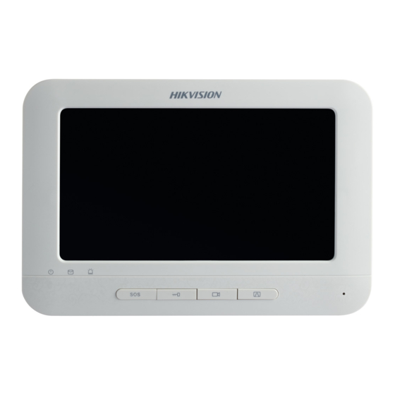
Page 14: Appearance Of Ds-Kh6310-W/Ds-Kh6310
Video Intercom Indoor Station·User Manual 2.3 Appearance of DS-KH6310-W/DS-KH6310 Figure 2-5 Front Panel Figure 2-6 Rear Panel Table 2-3 Descriptions Description Power Supply Indicator Information Indicator Alarm Indicator... -
Page 15: Appearance Of Ds-Kh6310-W(L)/Ds-Kh6210(L)
Terminals and Interfaces of Cables Loudspeaker Hold down the SOS key to trigger a SOS alarm and upload the alarm message to the management center (iVMS-4200 client software or the master station). 2.4 Appearance of DS-KH6310-W(L)/DS-KH6210(L) Figure 2-7 Front Panel... - Page 16 Video Intercom Indoor Station·User Manual Figure 2-8 Rear Panel of DS-KH6310-W(L)/DS-KH6210(L) Table 2-4 Descriptions of DS-KH6310-W(L) Description Power Supply Indicator Information Indicator Alarm Indicator SOS Key Unlock Key Live View Key Management Center Key Microphone DC 12V Power Supply Network Interface...
- Page 17 Video Intercom Indoor Station·User Manual Table 2-5 Descriptions of DS-KH6210(L) Description Power Supply Indicator Information Indicator Alarm Indicator SOS Key (hold down) Return key (press) Direction keys▲and◄ Unlock Key (hold down) (press) Direction keys▼and► Live View Key (hold down) (press) Management Center Key Confirm key (press) (hold down)
-
Page 18: Typical Application
Video Intercom Indoor Station·User Manual 3 Typical Application Building Client Software Indoor Indoor Extension 1 Extension 2 Resident 1 Resident 2 Video/Audio Distributor Center Master Station (Master Station) Resident 1 Resident 2 Switch Resident 2 Resident 1 Estate LAN Master Station in Guard's Room Video/Audio Resident 1... -
Page 19: Terminals And Interfaces
Video Intercom Indoor Station·User Manual 4 Terminals and Interfaces 4.1 Terminals and Interfaces of DS-KH8501-WT/ DS-KH8500-T Figure 4-1 Rear Panel of DS-KH8501-WT/DS-KH8500-T Table 4-1 Descriptions of Terminals and Interfaces Name Interface Description TF Card Slot TF Card Slot Mechanical Mechanical Switch of Built-in Camera Switch +12V DC 12V Power Supply + Input... -
Page 20: Terminals And Interfaces Of Ds-Kh8301-Wt/ Ds-Kh8300-T
Video Intercom Indoor Station·User Manual Name Interface Description Grounding Grounding Grounding COM1 Alarm Relay Output Terminal 1 (Dry Contact) ALARM OUT (Alarm Output) COM2 Alarm Relay Output Terminal 2 (Dry Contact) JIN8 Zone Detector Input Terminal 8 JIN7 Zone Detector Input Terminal 7 JIN6 Zone Detector Input Terminal 6 JIN5... - Page 21 Video Intercom Indoor Station·User Manual Table 4-2 Descriptions of Terminals and Interfaces Name Interface Description TF Card Slot TF Card Slot Mechanical Mechanical Switch of Built-in Camera Switch +12V DC 12V Power Supply + Input Power Supply DC 12V GND - Input Network Network Interface (Support Private POE) Interface...
-
Page 22: Terminals And Interfaces Of Ds-Kh6310-W/ Ds-Kh6310
Video Intercom Indoor Station·User Manual 4.3 Terminals and Interfaces of DS-KH6310-W/ DS-KH6310 Figure 4-3 Rear Panel of DS-KH6310-W/DS-KH6310 Table 4-3 Descriptions of Terminals and Interfaces Name Interface Description +12V DC 12V Power Supply + Input Power Supply DC 12V GND - Input... -
Page 23: Terminals And Interfaces Of Ds-Kh6310-W(L)/ Ds-Kh6210(L)
Zone Detector Input Terminal 3 AIN2 Zone Detector Input Terminal 2 AIN1 Zone Detector Input Terminal 1 RS485+ Reserved 4.4 Terminals and Interfaces of DS-KH6310-W(L)/ DS-KH6210(L) Figure 4-4 Rear Panel of DS-KH6310-W(L)/DS-KH6210(L) Table 4-4 Descriptions of Terminals and Interfaces Name Interface Description... - Page 24 Video Intercom Indoor Station·User Manual Name Interface Description AIN2 Zone Detector Input Terminal 2 Grounding...
-
Page 25: Installation And Wiring
Video Intercom Indoor Station·User Manual 5 Installation and Wiring 5.1 Indoor Station Installation To install the indoor station onto the wall, an installation plate and a gang box are required. The gang box of 8-series and 6-series indoor stations is the same. 5.1.1 Installation Plate Hollow Area Figure 5-1 Dimensions of Installation Plate... - Page 26 Video Intercom Indoor Station·User Manual 2. Chisel a hole in the wall for inserting the gang box. The size of the hole should be 76 (width) × 76 (length) × 50 (depth) mm. 3. Insert the gang box into the hole. Figure 5-2 Insert the Gang Box 4.
- Page 27 Video Intercom Indoor Station·User Manual 6. After installing the installation plate, install the indoor station onto the installation plate according to the direction of the arrow, as shown in the figure below. Figure 5-4 Install the Indoor Station 7. Pull the device downwards to hook the indoor station with the installation plate after inserting the indoor station into the gang box.
-
Page 28: Indoor Station Wiring
Video Intercom Indoor Station·User Manual 5.2 Indoor Station Wiring 5.2.1 Wiring of DS-KH8501-WT/DS-KH8500-T/DS-KH8301-WT/ DS-KH8300-T Figure 5-6 Wiring of DS-KH8301-WT/DS-KH8300-T Indoor Station... - Page 29 Video Intercom Indoor Station·User Manual Figure 5-7 Wiring of DS-KH8501-WT/DS-KH8500-T Indoor Station...
- Page 30 Video Intercom Indoor Station·User Manual Table 5-1 Description of Indoor Station Interfaces Interface Description ALARM IN Connect alarm device, with one end of the device connecting to JINx and the other end connecting to GND (x indicates number between 1~8). ALARM OUT Connect alarm output devices.
-
Page 31: Wiring Of Ds-Kh6310-W/Ds-Kh6310
Video Intercom Indoor Station·User Manual 5.2.2 Wiring of DS-KH6310-W/DS-KH6310 Figure 5-8 Wiring of DS-KH6310-W/DS-KH6310 Indoor Station... -
Page 32: Wiring Of Ds-Kh6310-W(L)/Ds-Kh6210(L)
Video Intercom Indoor Station·User Manual 5.2.3 Wiring of DS-KH6310-W(L)/DS-KH6210(L) Figure 5-9 Wiring of DS-KH6310-W(L)/DS-KH6210(L) Indoor Station... -
Page 33: Before You Start
Video Intercom Indoor Station·User Manual 6 Before You Start For the first time use of the device, you are required to activate the device and set the device password. You can activate the device on the UI, via internet with Batch Configuration Tool, or with iVMS-4200 client software. -
Page 34: Video Intercom Device Set-Up Tool
Video Intercom Indoor Station·User Manual 7 Video Intercom Device Set-up Tool Purpose: You can assign the device to the community, active and set the device by using the video intercom device set-up tool. 7.1 Setting a Community Structure Purpose: You can set a community structure, based on the real community situation, on the video intercom device set-up tool, and then assign devices to the community accordingly. -
Page 35: Setting Community
Video Intercom Indoor Station·User Manual Figure 7-2 Project Settings 3. Click the Apply button to enable the settings. The default amount of project is 1 if the amount is not set in the textbox. 7.1.2 Setting Community Steps: 1. Check the checkbox of a certain project from the community structure. 2. -
Page 36: Setting Building
Video Intercom Indoor Station·User Manual If you check the checkbox of All, then all projects in the community structure will be selected, and will be added the same amount of community. 7.1.3 Setting Building Steps: 1. Check the checkbox of a certain community from the community structure. 2. -
Page 37: Setting Room
Video Intercom Indoor Station·User Manual Figure 7-5 Floor Settings 3. Click the Apply button to enable the settings. If you check the checkbox of All, then all buildings in the community structure will be added the same amount of floor. ... -
Page 38: Activating And Setting Indoor Station
Video Intercom Indoor Station·User Manual If you check the checkbox of All, then all floors in the community structure will be selected, and will be added the same amount of room. If you check the checkbox of a certain project, then all floors in the selected project will be added the same amount of floor. - Page 39 Video Intercom Indoor Station·User Manual 7. Click the Set button to accomplish the settings of indoor station. Figure 7-8 Indoor Station Settings Interface You can select one project or multiple projects; one community or multiple communities; one building or multiple buildings. ...
-
Page 40: Batch Configuration Tool
Video Intercom Indoor Station·User Manual 8 Batch Configuration Tool 8.1 Activating Device Remotely Purpose: The device cannot be operated until it is activated. You can remotely activate the device via Batch Configuration Tool or via iVMS-4200 client. Here take the Batch Configuration Tool as example, and for further information, please refer to the user manual in the disk. -
Page 41: Editing Network Parameters
Video Intercom Indoor Station·User Manual When the device is not activated, the basic operation and remote operation of device cannot be performed. 8.2 Editing Network Parameters Purpose: You can edit the network parameters of online devices. Steps: 1. Select an online device in the online devices list in the lower part of the batch configuration software interface. -
Page 42: Adding Device
Video Intercom Indoor Station·User Manual 8.3 Adding Device The software provides 4 ways for adding the devices. You can add the active online devices within your subnet, add devices by IP address, add devices by IP segment or add devices by device port No. range. 8.3.1 Adding Online Devices Steps: 1. -
Page 43: Adding By Ip Address, Ip Segment Or Port No
Video Intercom Indoor Station·User Manual Figure 8-6 Login Dialog Box 4. Enter the user name and password. 5. Click the OK button to save the settings. Only the devices that are successfully logged in will be added to the device list for configuration. - Page 44 Video Intercom Indoor Station·User Manual 3. Click the OK button to add the device to the device list. Adding by IP Segment Purpose: You can add many devices at once whose IP addresses are among the IP segment. Steps: 1.
-
Page 45: Remote Configuration
Video Intercom Indoor Station·User Manual 5. Click the OK button to search and add the devices of which port numbers are within the defined port No. range to the device list. You cannot add the device(s) to the device list if the user name and password are not identical. - Page 46 Video Intercom Indoor Station·User Manual General Click the General button to enter device general parameters settings interface. You can view and edit the device name and device ID. Figure 8-13 Device General Parameters Settings Interface Time Steps: 1. Click the Time button to enter the device time settings interface. Figure 8-14 Time Settings Interface 2.
- Page 47 Video Intercom Indoor Station·User Manual You can operate the system management and remote upgrading on the system maintenance interface. Steps: 1. Click the System Maintenance button to enter the system maintenance interface. 2. Select System Management or Remote Upgrade. System Management •...
- Page 48 Video Intercom Indoor Station·User Manual Click the Yes button to restore all parameters of device and reset the device to inactive status. • Import Configuration File Click the Import Configuration File button to pop up the import file window. Figure 8-18 Import Configuration File Window Select the path of remote configuration files.
- Page 49 Video Intercom Indoor Station·User Manual Select the save path of remote configuration files. Click the Save button to export the configuration file, and pop up an information box for exporting. Figure 8-21 Information Box for Exporting Remote Upgrade • Reboot Click the button to pop up the window for opening upgrade file.
- Page 50 Video Intercom Indoor Station·User Manual Figure 8-24 User Information Editing Interface 2. Select the user to edit and click the Modify button to enter the user parameter interface. Figure 8-25 User Parameter Interface 3. Enter the new password, and confirm it. 4.
-
Page 51: Video Intercom
Video Intercom Indoor Station·User Manual Figure 8-26 RS485 Parameters The DS-KH6210(L) and DS-KH6310-W(L) indoor stations do not support RS485 settings. 8.4.2 Video Intercom Click the Video Intercom button on the remote configuration interface to enter the video intercom parameters settings: Device Number Configuration, Time Parameters, Password, Zone Configuration, IP Camera Information, and Volume Input and Output Configuration. - Page 52 Video Intercom Indoor Station·User Manual Figure 8-28 Device Number Configuration Interface (Indoor Extension) 2. Select the device type: Indoor Station or Station Extension. Indoor Station: Enter the Room No.. Station Extension: Enter the serial No.. 3. Select Yes or No from the drop-down list menu of auto login. 4.
- Page 53 Video Intercom Indoor Station·User Manual For indoor station, maximum ring duration is the maximum duration of indoor station when it is called without being received. The range of maximum ring duration varies from 30s~60s. For indoor station, maximum live view time is the maximum time of playing live view of the indoor station.
- Page 54 The exit delay is the time between you enable the arming mode and the arming takes effect. The DS-KH6201(L) and DS-KH6310-W(L) only support 2 zones. IP Camera Information Purpose: You can add, delete and modify network IP cameras with two ways of getting stream:...
- Page 55 Video Intercom Indoor Station·User Manual Indoor extension does not support the IP Camera Information settings. The DS-KH6210(L) does not support the IP Camera Information settings. Steps: 1. Click the IP Camera Information button to enter IP camera information interface. Adding Network IP Camera Figure 8-33 IP Camera Information Interface Click the Add button on the IP camera information interface to pop up the...
-
Page 56: Network
Video Intercom Indoor Station·User Manual Figure 8-35 IP Camera Adding by URL • Set a device name. • Enter the URL address 2. Click the OK button. 8.4.3 Network Click the Network button on the remote configuration interface to set network configurations: Local Network Configuration, and Linked Network Configuration. - Page 57 Video Intercom Indoor Station·User Manual After editing the local network parameters of device, you should add the devices to the device list again. Linked Devices Network Configuration Purpose: In the linked devices network configuration interface, you can configure the network parameters of master stations, SIP servers and management centers of the same LAN.
- Page 58 Video Intercom Indoor Station·User Manual For indoor station, the linkage between indoor station and master station can be realized after adding master station IP Address, For indoor station, the video intercom among indoor stations of same building can be realized after adding the door station IP Address, ...
-
Page 59: Setting The Door Station Via Ivms-4200
Video Intercom Indoor Station·User Manual 9 Setting the Door Station via iVMS-4200 9.1 System Configuration After running the iVMS-4200, enter Control Panel -> Maintenance and Management -> System Configuration -> Video Intercom to configure the video intercom parameters accordingly. You can configure the ringtone, Max. ring duration, Max. speaking time with indoor station and Max. -
Page 60: Adding Group
Video Intercom Indoor Station·User Manual Indoor extension does not support the Group Management settings. 9.3.1 Adding Group 1. Click the Group Management tab to enter the group management interface. Figure 9-2 Group Management Interface 2. Click the button on the right group list to pop-up group adding dialog box. 3. -
Page 61: Assigning Devices To Group
Video Intercom Indoor Station·User Manual Figure 9-4 Group Adding Interface (Outer Door Station) 1) Check the checkbox of outer door station. 2) Enter the project No.. Selecting Other as Group Type Figure 9-5 Group Adding Interface (Other) 1) Check the checkbox of other. 2) Enter the name. -
Page 62: Modifying Device Information
Video Intercom Indoor Station·User Manual Figure 9-6 Resident Adding Interface 2. Check the checkbox of device and enter the Room No. of indoor stations to assign the device to the community. 3. Click the OK button to save the settings. 9.3.3 Modifying Device Information 1. -
Page 63: Card Management
Video Intercom Indoor Station·User Manual 9.4 Card Management Purpose: You can add unauthorized cards to the community and then you can assign the cards to the corresponding indoor station and outdoor stations. For example, if there are 3 residents living in Room 401, you can assign 3 cards to No. 401 indoor Station. For each indoor station, you can assign many cards, and you can assign these cards to the door station from same building. - Page 64 Video Intercom Indoor Station·User Manual Figure 9-1 Adding in Batch Figure 9-2 Adding by Single or Card Reader 5. Click the OK button to save the settings. Two card types are recommended. Resident card is used by residents living in the community, and other card is used by visitors (guest, serviceman, etc.) in the community.
- Page 65 Video Intercom Indoor Station·User Manual 1) Select Community on the left and the indoor stations of the community will be listed in the resident list. Figure 9-4 Resident Card Issuing Interface 2) Click the button to pop up card selection interface for selecting unauthorized cards to be issued to the indoor station.
- Page 66 Video Intercom Indoor Station·User Manual Figure 9-6 Other Card Issuing Interface Click the button to pop up card selection interface for selecting unauthorized cards to be issued to the indoor station. Figure 9-7 Other Card Selection Interface 3) Check the checkboxes of the cards that need issuing to the indoor station, and check the checkbox of door stations, doorphones and outer door stations (only resident cards can be assigned to indoor stations).
- Page 67 Video Intercom Indoor Station·User Manual 2) Click the Delete Card button to pop up unauthorized card deleting box. Figure 9-8 Card Deleting Information Box 3) Click the OK button to delete the card(s). Deleting Issued Card 1) On the resident/other card issuing interface, select a community group or an Other group.
- Page 68 Video Intercom Indoor Station·User Manual Figure 9-10 Template File Exporting Interface 3. Fill in the template of the batch import file and click the Save button to save it. 4. Click the button to select the batch import file. Figure 9-11 Batch Import File Opening Interface 5.
-
Page 69: Normal Card Management
Video Intercom Indoor Station·User Manual Figure 9-12 Batch Export Interface 2. Select the saving file path and click the Save button. 3. Generate an excel file in the saving directory after exporting unauthorized cards in batch. 9.4.2 Normal Card Management On card management interface, click the normal card button to enter the normal card interface for listing normal cards including resident card and other card. -
Page 70: Notice Management
Video Intercom Indoor Station·User Manual After issuing each card via iVMS-4200, the device plays the voice prompt: Issuing card finished. 9.5 Notice Management Indoor extension does not support the Notice Management settings. 9.5.1 Creating Notice Information Purpose: You can create notice information and send it to residents. Steps: 1. -
Page 71: Querying Notice Information
Video Intercom Indoor Station·User Manual Figure 9-2 Resident Select 3. Select the resident to send the notice information, and click the OK button. 4. Input the subject, select the info type and add the picture (optional). 5. Input the information and click the Send button to send the notice. ... -
Page 72: Querying Call Logs
Video Intercom Indoor Station·User Manual 3. Click the Query button to search the notice information. 4. Click the Details button to view the detailed information of selected notice. You can resend the notice information failed to be received or unread by residents. Figure 9-4 Information Details 5. -
Page 73: Querying Unlocking Log
Video Intercom Indoor Station·User Manual 9.5.4 Querying Unlocking Log Steps: 1. Click the Query Unlocking Logs button to enter query unlocking logs interface. 2. Select the unlocking type, device type, and set the start time and end time. Figure 9-6 Query Unlocking Logs 3. - Page 74 Video Intercom Indoor Station·User Manual Figure 9-8 Device Arming Control Figure 9-9 Alarm Events After adding the device to the client software, it will be armed automatically.
-
Page 75: Local Operation
Video Intercom Indoor Station·User Manual 9 Local Operation Here the local operation of indoor stations with touch screen is taken as example. The DS-KH6201(L) should be operated with physical keys. The SOS key works as a return key; the Unlock key works as direction keys ▲and◄ to turn up and left; the Live View key works as direction keys ▼and►... -
Page 76: User Interface Description
Video Intercom Indoor Station·User Manual You must create a password to activate the indoor station for your first time usage and when it is not activated. Only after activating the indoor station, you can operation it locally and remotely. ... -
Page 77: User Interface Of Indoor Extension
Video Intercom Indoor Station·User Manual Only DS-KH8501-WT/DS-KH8500-T/DS-KH8301-WT/DS-KH8300-T indoor stations support TF card. DS-KH6210(L) only has one interface page. Figure 9-4 User Interface of DS-KH6210(L) 10.2.2 User Interface of Indoor Extension Figure 9-5 User Interface of Indoor Extension Only DS-KH8501-WT/DS-KH8500-T/ DS-KH8301-WT/DS-KH8300-T indoor extensions support TF card. - Page 78 Video Intercom Indoor Station·User Manual Table 10-1 Description of Status Icons Icon Definition Description The communication between indoor station, door station and master station is normal. Normal Status. And the communication between indoor station and indoor extension is normal. The indoor Please check the network cable or Wi-Fi station is offline.
-
Page 79: Indoor Extension Status
Video Intercom Indoor Station·User Manual Icon Definition Description No TF card is inserted in the indoor station. 10.2.4 Indoor Extension Status Table 10-2 Description of Status Icons Icon Definition Description The communication between indoor station Normal Status. and indoor extension is normal. The indoor Please check the network cable or Wi-Fi extension is... -
Page 80: Arming Status
Video Intercom Indoor Station·User Manual 10.2.5 Arming Status Purpose: Arming status displays the arming situation of your room from 4 types: sleeping, custom, outdoor, and indoor. You can arm/disarm the room manually, and when the arming status is enabled, the arming status will display on the main interface. Steps: 1. -
Page 81: Password Settings
Video Intercom Indoor Station·User Manual 10.3.1 Password Settings Purpose: You can edit the admin password (configuration password), duress code, unlock password and arm/disarm password of the indoor station. You can edit the admin password (configuration password) and arm/disarm password of the indoor extension. -
Page 82: Sound Settings
Video Intercom Indoor Station·User Manual Figure 9-9 Password Changing Interface 4. Enter the old password to change it. 5. Enter the new password and confirm it. 6. Press the tab to save the settings. The default admin password (configuration password) is 888999; ... -
Page 83: No Disturbing Settings
Video Intercom Indoor Station·User Manual Figure 9-10 Sound Settings Interface (Indoor Station) 2. Select the ringtone for the device. 3. Set the ring duration, and call forwarding for the device. 4. Set the microphone volume, and loudspeaker volume. 5. Switch to enable the touch sound and auto-answer function. -
Page 84: Arming Mode Settings
Video Intercom Indoor Station·User Manual Figure 9-12 No Disturbing Settings Interface 2. Select no disturbing mode: All Day or Scheduled. All Day: Switch to enable no disturbing mode. Scheduled: Switch to enable no disturbing mode. Set the start time and the end time. ... -
Page 85: Zone Settings
Arm mode settings should be configured with the settings of arming status on the the user interface of the device. The DS-KH6201(L) and DS-KH6310-W(L) indoor stations only support 2 zones. 10.3.5 Zone Settings Purpose: You can set the zone type, alarm type and delay time and other parameters of 8 zones. -
Page 86: System Maintenance
Set the alarm type as delay alarm, and you can set the enter delay duration and exit delay duration. For Gas Detector and Smoke Detector, the alarm type is set as default 24h alarm. The DS-KH6201(L) and DS-KH6310-W(L) indoor stations only support 2 zones. 10.3.6 System Maintenance Purpose: You can format TF card, clear the screen, view the version information of the indoor station and restore the system on the system maintenance interface. -
Page 87: Configuration Settings
Figure 9-16 System Maintenance Interface Only DS-KH8500-T/DS-KH8501-WT/DS-KH8300-T/DS-KH8301-WT models indoor stations support TF card function. Only DS-KH8501-WT/DS-KH8301-WT/DS-KH6310-W/DS-KH6310-W(T) models indoor stations have the Upgrade tab on the system maintenance interface. After clearing the screen, you can press and hold to exit clear screen mode. - Page 88 Video Intercom Indoor Station·User Manual The maximum live view duration varies from 10 seconds to 60 seconds. Figure 9-17 Local Information Settings (Indoor Station) Figure 9-18 Local Information Settings (Indoor Extension) Setting Network Purpose: Network connection is mandatory for the use of the indoor station. Steps: 1.
- Page 89 Video Intercom Indoor Station·User Manual Enable DHCP function to obtain an IP address automatically. Please enable Same LAN function if the indoor stations and indoor extensions are in the same local area network with other video intercom devices in a community, or the indoor extensions will not work normally.
- Page 90 Video Intercom Indoor Station·User Manual The DS-KH6201(L) indoor station does not support adding IP camera, DVR/DVS/NVR, or doorphone. Connecting Main Door Station Steps: 1. Press the Settings tab on the touch screen. 2. Press the Configuration tab and enter the admin password (configuration password). 3.
- Page 91 Video Intercom Indoor Station·User Manual 5. Press the IP Camera tab, DVR/DVS/NVR tab, or Doorphone tab to pop up corresponding adding dialogue box. Figure 9-22 IP Camera Adding Interface Figure 9-23 DVR/DVS/NVR Adding Interface Figure 9-24 Doorphone Adding Interface 6. Enter the corresponding information. 7.
- Page 92 Video Intercom Indoor Station·User Manual When the IP camera added successfully, you can get the live view of main door station on the live view interface. The indoor station can add 8 doorphones at most, and add 16 cameras and DVR/DVS/NVR channels in total.
- Page 93 Video Intercom Indoor Station·User Manual Figure 9-26 SCP Adding Interface 5. Enter the IP address and port No. of the security control panel. 6. Press the tab on the upper left corner of the dialogue box. Indoor extension does not support connecting to the security control panel. Synchronizing Time Steps: 1.
-
Page 94: Call Settings
Video Intercom Indoor Station·User Manual Restoring Default Settings Steps: 1. Press the Settings tab on the touch screen. 2. Press the Configuration tab and enter the admin password (configuration password). 3. Press the Restore tab to enter the default settings restoring interface. 4. -
Page 95: Calling Resident
Video Intercom Indoor Station·User Manual Hold down an added contact to open the contact handling menu. Press the Call tab to start the video call with the contact. Press the Edit tab to modify the contact information. ... -
Page 96: Receiving Call
Video Intercom Indoor Station·User Manual Figure 9-30 Call Resident Interface 10.4.3 Receiving Call Indoor extension does not support this function. Purpose: You can call the indoor station from the door station, the master station, or iVMS-4200 client. Figure 9-31 Calling from Center (Master Station or iVMS-4200) Figure 9-32 Calling from Door Station ... -
Page 97: Viewing Call Logs
Video Intercom Indoor Station·User Manual Press the tab to capture the live view picture when speaking with the door station. And prompts “Captured” will display on the screen. 10.4.4 Viewing Call Logs Steps: 1. Press the tab on the touch screen to enter the call log interface. Figure 9-33 Call Logs Interface 2. -
Page 98: Calling Management Center And Calling Elevator
Video Intercom Indoor Station·User Manual 10.4.5 Calling Management Center and Calling Elevator Purpose: You can call elevator and call management center from the indoor station/extension. Calling Management Center Steps: 1. Press the tab to enter the contact list interface, or press the tab to enter the live view interface. -
Page 99: Information Management
Video Intercom Indoor Station·User Manual If calling elevator when it is not in the video intercom with door station, the elevator will not arrive at the floor of the resident. If calling elevator during the video intercom with door station, the elevator will arrive at the floor of the door station. - Page 100 Video Intercom Indoor Station·User Manual Figure 9-36 Alarm Logs Interface (Indoor Station) Figure 9-37 Alarm Logs Interface (Indoor Extension) 5. Press the Capture Log tab to view capture logs. Figure 9-38 Capture Logs Interface (Indoor Station) Figure 9-39 Capture Logs Interface (Indoor Extension)
-
Page 101: Live View
For DS-KH8501-WT/DS-KH8500-T/DS-KH8301-WT/DS-KH8300-T models, it requires TF card for saving visitor messages and capture logs of the indoor stations. For DS-KH6310/DS-KH6310-W/DS-KH6310-W(L)/DS-KH6210(L) models, it is the internal memory of the indoor station that saves the visitor messages and capture logs. - Page 102 Video Intercom Indoor Station·User Manual 2. Press the Door Station tab to enter the live view interface of door station. Figure 9-41 Live View of Door Station 3. Press the IP Camera tab to enter the live view interface of IP cameras. Figure 9-42 Live View of IP Camera On the door station live view interface, press the Unlock tab to open the unit door.
-
Page 103: Appendix
Video Intercom Indoor Station·User Manual Appendix Installation Notice While installing the indoor station, please make sure that the distance between any two devices is far as possible to avoid the howling and echo. The distance between two devices is recommended to be more than 10 meters. Here the devices refer to indoor station, outdoor station and master station. - Page 104 Video Intercom Indoor Station·User Manual Switch Video Compression H.264 Standard Resolution 640 × 480 Video Frame Rate PAL: 25 fps, NTSC: 30 fps Display Parameters Display Screen 10-Inch Colorful TFT LCD Resolution 1024 × 600 Operation Method Capacitive Touch Screen, Touch Key Operation Interface Flattened UI Operation Interface Audio Parameters...
-
Page 105: Specification Of Ds-Kh8301-Wt/Ds-Kh8300-T
Video Intercom Indoor Station·User Manual Working Temperature -10° C to +55° C (14° F to 131° F) Working Humidity 10% to 90% Dimension 260 mm × 180 mm × 18 mm (10.2" × 7.1" × 0.7") (L x W x H) Certification FCC, IC, CE, C-TICK, ROHS, REACH, WEEE Specification of DS-KH8301-WT/DS-KH8300-T... -
Page 106: Specification Of Ds-Kh6310-W/Ds-Kh6310
10% to 90% Dimension 217 mm × 142 mm × 26 mm (8.5" × 5.6" × 1.0") (L x W x H) Certification FCC, IC, CE, C-TICK, ROHS, REACH, WEEE Specification of DS-KH6310-W/DS-KH6310 Model DS-KH6310-W DS-KH6310 Parameters System Parameters Processor... -
Page 107: Specification Of Ds-Kh6310-W(L)/Ds-Kh6210(L)
10% to 90% 195.8 mm × 132.8 mm × 17.5 mm (7.7" × 5.2" Dimension (L x W x H) ×0.7") Certification FCC, IC, CE, C-TICK, ROHS, REACH, WEEE Specification of DS-KH6310-W(L)/DS-KH6210(L) Model DS-KH6310-W(L) DS-KH6210(L) Parameters System Parameters Processor High-Performance Embedded SOC Processor... - Page 108 Video Intercom Indoor Station·User Manual Physical Button Capacitive Touch Operation Method Screen, Physical Button Operation Interface Flattened UI Operation Interface Audio Parameters Audio Input Build-in Omnidirectional Microphone Audio Output Build-in Loudspeaker Audio Compression G.711 U Standard Audio Compression 64 Kbps Rate Audio Quality Noise Suppression and Echo Cancellation...
- Page 109 Video Intercom Indoor Station·User Manual...
Need help?
Do you have a question about the DS-KH6310-W and is the answer not in the manual?
Questions and answers