Memmert HCP Operating Manual
Humidity chamber
Hide thumbs
Also See for HCP:
- Quick start manual (56 pages) ,
- Quick start manual (40 pages) ,
- Quick start manual (45 pages)
Table of Contents
Advertisement
Quick Links
Advertisement
Table of Contents

Related Manuals for Memmert HCP


Summary of Contents for Memmert HCP
- Page 1 Operating manual Humidity chamber HCP www.memmert.com...
-
Page 2: Table Of Contents
Table of Contents Table of Contents 1. About this Manual 2. Safety 2.1 Terms and Symbols Used ............................2.1.1 Terms Used..............................2.1.2 Symbols Used .............................. 2.2 Product Safety and Dangers............................2.3 Requirements to be met by Operating Personnel......................2.4 Responsibility of the Owner ............................2.5 Product Use ................................ - Page 3 Table of Contents 4.6.2 Anti-tilt bracket ............................20 4.6.3 Adjusting the Doors............................20 5. Putting into Operation 5.1 Putting into Operation for the First Time........................22 5.2 Connecting the Unit to the Power Supply ........................22 5.3 Water specifications ..............................22 5.4 Connecting and Filling the Water Tank........................
- Page 4 Table of Contents 8.3 Setup..................................43 8.3.1 Overview..............................43 8.3.2 IP Address and Subnet Mask ........................44 8.3.3 Unit ................................45 8.3.4 Temperature Monitoring ..........................45 8.3.5 Timer Mode ..............................45 8.3.6 Remote Control ............................45 8.3.7 Gateway............................... 46 8.4 Date and Time................................46 8.5 Calibrate..................................
-
Page 5: About This Manual
Purpose and target audience This manual describes the design, function, transport, operation and maintenance of the product series Humidity chambers HCP. It is intended for use by trained personnel employed by the owner who are tasked with operating and/or maintaining the unit. - Page 6 E-mail: sales@memmert.com www.memmert.com International After Sales Memmert GmbH + Co. KG Willi-Memmert-Straße 90-96 | D-91186 Büchenbach | Germany Tel. +49 9171 9792 911 E-mail: service@memmert.com www.memmert.com If you have any queries, please always quote the product number on the nameplate.
-
Page 7: Safety
Safety Safety Terms and Symbols Used In this manual and on the unit itself, certain recurring terms and symbols are used to warn you of hazards or give you information that is important in order to prevent injury or damage. To avoid accidents and damage, observe and follow these instructions. These terms and symbols are explained below. - Page 8 Safety DANGER Live parts When covers are removed, live parts are exposed and contact with these parts may result in electric shock. Electric shock can have serious health consequences including death. – Only authorised persons may carry out electrical installation work. –...
-
Page 9: Requirements To Be Met By Operating Personnel
Product Use 2.5.1 Intended Use Humidity chambers HCP must only be used for temperature and climate testing of materials and substances in the context of the procedures and specifications described in this manual. 2.5.2 Improper Use Any other use is improper and may result in danger and damage. -
Page 10: Behaviour In Case Of Malfunctions And Irregularities
Safety The manufacturer is not liable for any damage, danger or injuries that emanating from unauthorised changes or alterations, or from non-compliance with the provisions in this manual. Behaviour in case of Malfunctions and Irregularities The unit must only be used in a flawless condition. If you, as the operator, notice irregularities, malfunctions or damage, immediately turn off the unit and inform your line manager. -
Page 11: Construction And Description
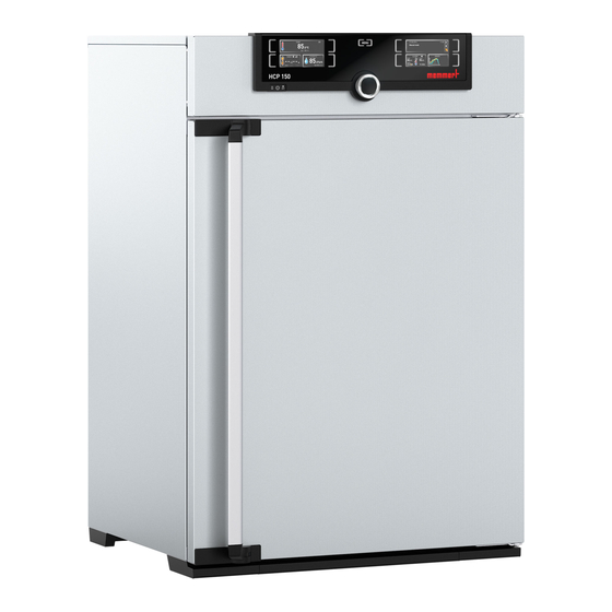
Construction and Description Construction and Description Design 1 ControlCOCKPIT with capacitive 2 Main switch function keys and LCD displays 3 Interior fan 4 Stainless steel perforated shelf 5 Inner glass door 6 Nameplate Description of Function Air is heated inside the appliance from all sides by means of large-area heating. The chamber is humidified by a hot steam generator on the back of the appliance which allows water to evaporate from a tank at a set rate. -
Page 12: Materials
Materials For the outer housing, MEMMERT processes stainless steel (Mat. No. 1.4016 – ASTM 430) for the chamber, stainless steel (Mat. No. 1.4301 – ASTM 304) is used, which stands out through its high stability, optimal hygienic properties and corrosion-resistance to many (but not all) chemical compounds (caution must be exercised with chlorine compounds, for example). -
Page 13: Connections And Interfaces
Construction and Description Connections and Interfaces 3.6.1 Electrical Connection This unit is designed for operation on an electrical power system with a maximum system impedance Z at the point of transfer (service line) of 0.292 Ohm. The operator must ensure that the unit is only operated on an electrical power system that meets these requirements. -
Page 14: Technical Data
Construction and Description 1 Type designation 2 Operating voltage 3 Applicable standard 4 Degree of protection 5 CE conformity 6 Manufacturer's address 7 Information regarding disposal 8 Temperature range 9 Connected loads / power ratings 10 Appliance number See also 2 Design [} 11] Technical Data Appliance size... -
Page 15: Applied Directives And Standards
We confirm that we always draw the attention of our suppliers to the legal restrictions on materials in accordance with our Company Standard for Material Compliance of Memmert GmbH + Co KG to ensure they take the original publications by the legislative authority into consideration at all times. -
Page 16: Ambient Conditions
3.9.2.1 REACH information of Memmert GmbH + Co. KG acc. to Regulation (EG) No. 1907/2006, Art. 33 Based on current knowledge, we confirm that products or sub-products containing substances of very high concern (SVHC in the specified components) in the Candidate List with concentrations higher than 0.1 mass % are installed in the appliances we supply:... -
Page 17: Optional Accessories
Construction and Description ■ Operating manual ■ Safety data sheet Calibration certificate ■ ■ Separately packaged fastening material for wall mounting (see }4.6.2 Anti-tilt bracket). See also 2 Anti-tilt bracket [} 20] 3.12 Optional Accessories With an Ethernet to USB converter it is possible to connect the Ethernet connection of the appliance to the USB port of a computer/laptop. -
Page 18: Delivery, Transport And Setting Up
Delivery, Transport and Setting Up Delivery, Transport and Setting Up Safety CAUTION Lifting the appliance incorrectly The appliance is heavy. The appliance is heavy, so you could injure yourself if you try to lift it on your own. – Make sure that a sufficient number of people are on hand to lift and carry the appliance. -
Page 19: Unpacking
– Always attach the appliance to a wall with the anti-tilt bracket. – In case there is not enough space to fasten the appliance to a wall, do not put the appliance into operation and do not open the door. – Contact Memmert service. 4.6.1 Preconditions ü... -
Page 20: Anti-Tilt Bracket
There are two adjusting screws on each door for this purpose; one at the top and one at the bottom. First, adjust the setting at the top of the door and, if this is not sufficient, adjust the bottom. A service video which explains how to adjust the door is available: www.memmert.com/de/downloads/media/service-videos/ D39303 02/2024... - Page 21 Delivery, Transport and Setting Up 1. Open the door. 2. Loosen the screws. 3. Adjust the position of the door. 4. Tighten the screws again. 5. Check the position of the door. 6. Readjust if required. D39303 02/2024...
-
Page 22: Putting Into Operation
2 Nameplate [} 13] 2 Technical Data [} 14] Water specifications Only water with the following specifications may be used in Memmert units: ■ Demineralised water and distilled water (a variety of terms are used commercially for this) that is residue-free when it evaporates, according to regulation VDE 0510 and DIN 43530... -
Page 23: Connecting And Filling The Water Tank
Putting into Operation ■ Conductivity of approx. > 1; < 10 µS/cm ■ neutral pH value (between 5 and 7) Chlorine-free ■ The use of double-distilled water / ultrapure water / other highly purified water (a variety of terms are also commonly used) with an electrical conductance below about < 1 µS/cm must be avoided. -
Page 24: Operation And Control
Operation and Control Operation and Control WARNING Hot surfaces Depending on the operating situation, the unit and the load may be hot. Contact with hot surfaces may have serious health consequences due to burns! – Allow the unit to cool down. –... -
Page 25: Loading The Appliance
Operation and Control 2. To close the door, push the door closed and push the door handle to the side. If the door stays open for a certain amount of time during operation, an alarm will sound. It can be stopped by pressing the confirmation key. Loading the Appliance WARNING Poisonous or explosive vapours and gases... -
Page 26: Operating The Appliance
Operation and Control See also 2 Materials [} 12] 2 Technical Data [} 14] Operating the Appliance 6.4.1 ControlCOCKPIT In manual operation, the desired parameters are entered at the ControlCOCKPIT on the front of the appliance. You can also make basic settings here (menu mode). Warning messages are also displayed, e.g. -
Page 27: Basic Operation
Operation and Control 13 Activation key for setting the temperature and humidity 14 Display of the temperature and humidity monitoring monitoring 15 Graphic representation of setpoint and actual values 16 Activation key for graphic representation 6.4.2 Basic Operation In general, all settings are made as follows: Activate the desired parameter (e.g. -
Page 28: Manual Mode
Operation and Control Programme Mode The appliance automatically runs programme sequences which have been defined using AtmoCONTROL software at a computer / laptop and then transferred to the appliance from a USB stick or via Ethernet. }6.5.3 Programme Mode ■ Remote control mode Via remote control ■... -
Page 29: Digital Backwards Counter
Operation and Control When the appliance heats up, the humidity is dynamically adjusted to the setpoint depending on the dew point of the chamber temperature. Humidity Setting range, see }3.8 Technical Data Humidification is indicated by the symbol. Dehumidification is indicated by the symbol. -
Page 30: Programme Mode
Operation and Control Once the timer has elapsed, the display shows 00h:00m. ■ All functions are switched off. ■ In addition, an alarm sounds, and can be turned off by pressing the confirmation key. 5. To switch off the timer, press the activation key again to display the timer. 6. - Page 31 Operation and Control 3. To start the programme, press the confirmation key. ð The programme is executed. The display shows: ■ the programme name ■ the name of the first programme segment ■ the current cycle (in case of loops) You cannot change any parameters at the appliance while a programme is running.
-
Page 32: Monitoring Function
Operation and Control Monitoring Function 6.6.1 Temperature Monitoring The appliance is equipped with multiple overtemperature protection in accordance with DIN 12880. This is designed to prevent damage to the chamber load and/or appliance in case of a malfunction: ■ electronic temperature monitoring (TWW/TWB) automatic temperature monitor (ASF) ■... -
Page 33: Temperature Selector Limiter (Twb)
Operation and Control 6.6.3 Temperature Selector Limiter (TWB) In programme mode, the current programme is resumed for TWB alarms of up to 15 minutes. If the alarm is active for more than 15 minutes, the programme is cancelled. 6.6.4 Automatic Temperature Monitor (ASF) ASF is a monitoring device that automatically follows the set temperature setpoint within an adjustable tolerance band. -
Page 34: Adjusting The Temperature Monitoring
Operation and Control 6.6.6 Adjusting the Temperature Monitoring 1. Press the activation key to the left of the ALARM display. ð The temperature monitoring setting is automatically activated . 2. By turning the turn control, adjust the desired lower alarm limit. The lower alarm limit cannot be higher than the upper alarm limit. -
Page 35: Humidity Monitoring
Operation and Control 9. Press the confirmation key to confirm. ð Temperature monitoring is now active. In menu mode you can set, whether an alarm should be accompanied by an acoustic signal (see }8.7 Acoustic Signals). See also 2 Acoustic Signals [} 51] 6.6.7 Humidity Monitoring If humidity monitoring has been triggered, this is indicated by the humidity display: the... -
Page 36: Graph
Operation and Control 7. Press the confirmation key to confirm. 8. Press the activation key on the side to exit the Alarm display. ð Humidity monitoring is now active. See also 2 Acoustic Signals [} 51] 2 Malfunctions, Warning and Error Messages [} 38] Graph The GRAPH display provides an overview of the chronological sequence of the set values and the actual values as a curve. -
Page 37: Ending Operation
Operation and Control 4. Press the confirmation key to confirm. ð The humidity profile is displayed. You can displace the display range and also zoom in/out as described in 6.7.1 Temperature Curve. See also 2 Temperature Curve [} 36] Ending Operation WARNING Hot surfaces Depending on the operating situation, the unit and the load may be hot. -
Page 38: Malfunctions, Warning And Error Messages
– Follow the measures listed in the event of a malfunction. – Contact Memmert International After Sales. Do not try to rectify appliance errors yourself; instead you should contact Memmert International After Sales or an authorised customer service point. In case of enquiries, please always state the model and appliance number on the nameplate (see }3.7 Nameplate). -
Page 39: Humidity Monitoring
Malfunctions, Warning and Error Messages Description Cause Action Temperature alarm and TWB is displayed Temperature selector limiter (TWB) has Switch off the alarm by pressing the ■ switched off the heating permanently. confirmation button ■ Increase the difference between the monitoring temperature and the set point temperature –... -
Page 40: Power Failure
Malfunctions, Warning and Error Messages Error description Cause of errors Rectifying errors Error message T:E-3 in the temperature Temperature working sensor faulty. The appliance can continue to be ■ display Monitoring sensor performs the measuring operated for a short time function. - Page 41 Malfunctions, Warning and Error Messages In remote control mode The previous values are restored. If a programme has been initiated via remote control, it is continued. D39303 02/2024...
-
Page 42: Menu Mode
Menu Mode Menu Mode In menu mode, you can make basic settings, load programmes and export protocols, as well as adjust the appliance. Before changing the menu settings, read the description of the respective functions on the following pages to avoid possible damage to the appliance and/or chamber load. ▶... -
Page 43: Setup
Menu Mode If no new values are entered or confirmed for approx. 30 seconds, the appliance automatically restores the former values. Activate the desired setting (in this example the language): 1. To do so, press the activation key to the left or right of the respective display. ð... -
Page 44: Ip Address And Subnet Mask
Menu Mode If the Setup menu contains more entries than can be displayed, this is indicated by the display “1/2”. This means that there is a second “page” of entries. To display the hidden entries, use the turn control to scroll beyond the lowest entry. The page display then changes to “2/2”. -
Page 45: Unit
Menu Mode 5. After setting the last three digits, confirm the new IP address by pressing the confirmation key. ð The overview is displayed once again. ð The subnet mask can be set in the same way. 8.3.3 Unit Here, you can choose whether the temperature is displayed in °C or °F. 8.3.4 Temperature Monitoring Here, you can choose which temperature protection class in accordance with... -
Page 46: Gateway
Menu Mode ■ Write + Alarm When the appliance is in remote control mode, the symbol appears in the temperature display. In the settings Write + Read and Write + Alarm, the appliance cannot be controlled at the ControlCOCKPIT until the remote control has been switched off (Off setting) or set to Read Only. -
Page 47: Calibrate
Menu Mode 7. Confirm the selection by pressing the confirmation key. ð The adjustment options are highlighted. 8. Set summertime to off (✕) or on (✓) with the turn control – in this case on (✓). 9. Save the setting by pressing the confirmation key. The changeover between summer and winter time does not take place automatically. - Page 48 Menu Mode Example: Temperature deviation should be corrected 1. Press the activation key to the right of the CALIB display. ð The display is enlarged and the temperature adjustment option is automatically highlighted. 2. Press the confirmation key repeatedly, until the calibration temperature Cal2 is highlighted.
-
Page 49: Humidity Calibration
Menu Mode If all calibration correction values are set to 0.0 K, the factory calibration settings are restored. 8.5.2 Humidity Calibration Closed-loop humidity control can be adjusted according to customer requirements by means of three freely selectable calibration points. For each selected calibration point, a positive or negative calibration correction value between –10% and +10% can be set. -
Page 50: Programme
Menu Mode 6. Set the calibration correction value to 0.0%. 7. Save the setting by pressing the confirmation key. 8. Position the sensor of the calibrated reference instrument centrally in the working chamber of the appliance. 9. Close the door. 10. -
Page 51: Acoustic Signals
Menu Mode 4. With the turn control, select the programme you want to use. 5. Confirm the selection by pressing the confirmation key. ð The programme is now loaded, as indicated by the progress display. As soon as the programme is ready, Select is highlighted once again. To start the programme: 6. -
Page 52: Log
Menu Mode 2. Confirm the selection by pressing the confirmation key. ð The adjustment options are automatically highlighted. 3. With the turn control, select the desired setting – in this example OFF (✕). 4. Save the setting by pressing the confirmation key. If an acoustic signal sounds, it can be turned off by pressing the confirmation key. -
Page 53: User Id
Menu Mode 4. Apply the selection by pressing the confirmation key. ð The transfer starts ð and the status bar indicates the progress. As soon as the transfer is complete, a check mark appears in front of the period selected. ■... - Page 54 Menu Mode 3. Confirm the activation by pressing the confirmation key. ð The new USER ID data are transferred from the USB storage medium and activated. ð As soon as activation is complete, a check mark appears in front of the corresponding entry.
-
Page 55: Maintenance And Servicing
Maintenance and Servicing Maintenance and Servicing DANGER Live parts When covers are removed, live parts are exposed and contact with these parts may result in electric shock. Electric shock can have serious health consequences including death. – Only authorised persons may carry out electrical installation work. –... -
Page 56: Repairs And Service
Maintenance and Servicing Repairs and Service Repairs and service work may only be carried out by specialist Memmert personnel and qualified service providers. NOTICE Repairs and service work are described in a separate service manual. D39303 02/2024... -
Page 57: Storage, Transport And Disposal
Storage, Transport and Disposal Storage, Transport and Disposal 10.1 Storage and Transport The appliance may only be stored and transported under the following conditions: ■ in a dry enclosed, dust-free room ■ disconnected from the power supply Before storage, remove water tube and empty the water tank (see }5.4 Connecting and Filling the Water Tank). - Page 58 Notes D39303 02/2024...
- Page 59 D39303 02/2024...
- Page 60 Operating manual Humidity chamber HCP D39303 Effective 02/2024 English...
Need help?
Do you have a question about the HCP and is the answer not in the manual?
Questions and answers