Table of Contents
Advertisement
Quick Links
Advertisement
Table of Contents

Related Manuals for IEI Technology WAFER-LUKE


Summary of Contents for IEI Technology WAFER-LUKE
- Page 1 WAFER-LUKE...
- Page 2 WAFER-LUKE REVISION HISTORY Title WAFER-LUKE 3.5” Motherboad Revision Number Description Date of Issue Initial release September 2006 COPYRIGHT NOTICE The information in this document is subject to change without prior notice in order to improve reliability, design and function and does not represent a commitment on the part of the manufacturer.
-
Page 3: Table Of Contents
WAFER-LUKE Table of Contents INTRODUCTION....................15 1.1 WAFER-LUKE O ..................16 VERVIEW 1.1.1 WAFER-LUKE Models ..................16 1.1.2 WAFER-LUKE Applications ................16 1.1.3 WAFER-LUKE Benefits ................... 17 1.1.4 WAFER-LUKE Features .................. 17 1.2 WAFER-LUKE O ..................18 VERVIEW 1.2.1 WAFER-LUKE Connectors................19 1.3 T... - Page 4 2.20.2 Optional Accessory Items................34 CONNECTORS ...................... 35 3.1 P ..............36 ERIPHERAL NTERFACE ONNECTORS 3.1.1 WAFER-LUKE Layout ..................36 3.1.2 Peripheral Interface Connectors ..............37 3.1.3 External Interface Panel Connectors............... 38 3.1.4 On-board Jumpers ................... 39 3.2 I ..............40 NTERNAL...
- Page 5 4.2.1 Installation Notices ..................68 4.3 U ......................69 NPACKING 4.3.1 Unpacking Precautions..................69 4.3.2 Checklist......................70 4.4 WAFER-LUKE M ............. 70 OTHERBOARD NSTALLATION 4.4.1 Preinstalled Components ................. 71 4.4.2 Components to Install ..................71 4.4.3 DIMM Module Installation ................71 4.4.3.1 Purchasing the Memory Module...............
- Page 6 WAFER-LUKE 5.1 I ......................84 NTRODUCTION 5.1.1 Starting Setup....................84 5.1.2 Using Setup ...................... 84 5.1.3 Getting Help..................... 85 5.1.4 Unable to Reboot After Configuration Changes..........85 5.1.5 BIOS Menu Bar....................85 5.2 M ........................86 5.3 A ....................... 87 DVANCED 5.3.1 CPU Configuration..................
- Page 7 WAFER-LUKE 6.3 4- -1 D ................146 RIVER NSTALLATION 6.4 R ............... 155 UDIO RIVER NSTALLATION 6.5 LAN D ................. 164 RIVER NSTALLATION BIOS CONFIGURATION OPTIONS ..............175 A.1 BIOS C ................176 ONFIGURATION PTIONS WATCHDOG TIMER ..................179 ADDRESS MAPPING..................183 C.1 IO A...
- Page 8 Figure 3-18: RS-232/422/485 Serial Port Connector Location ........60 Figure 3-19: SATA Drive Connector Locations............61 Figure 3-20: USB Connector Pinout Locations............62 Figure 3-21: WAFER-LUKE CP Rear Panel...............63 Figure 3-22: VGA Connector ..................63 Figure 3-23: COM1 Serial Port Connector ..............64 Figure 3-24: RJ-45 Ethernet Connector ..............66 Figure 4-3: SO-DIMM Module Installation ..............72...
- Page 9 Figure 4-7: LCD Voltage Setup Jumper Pinout Locations ........79 Figure 4-8: COM2 Setup Jumper Pinout Locations ..........80 Figure 4-10: COM2 Voltage Setup Jumper Pinout Locations.........81 Figure 6-1: Access the WAFER-LUKE Drivers ............147 Figure 6-2: Setup Utility Icon .................. 148 Figure 6-3: 4 in 1 Icon ....................149 Figure 6-4: VIA Chipset Driver Installation Welcome Screen ......
- Page 10 WAFER-LUKE Figure 6-29: LAN Driver Installation ............... 172 Figure 6-30: Exit LAN Driver Setup ................ 173 ® OIEI Technology, Corp. 0-10...
- Page 11 WAFER-LUKE List of Tables Table 1-1: Technical Specifications ................22 Table 2-1: Power Consumption 1 ................33 Table 2-2: Power Consumption 2 ................33 Table 3-1: Peripheral Interface Connectors..............38 Table 3-2: External peripheral interface connectors ..........39 Table 3-3: On-board Jumpers ..................39 Table 3-4: +5VSB PS_ON Connector Pinouts ............40 Table 3-5: –12V Power Connector Pinouts...............41...
- Page 12 Table 4-3: Clear CMOS Jumper Settings ..............76 Table 4-4: CF Card Setup Jumper Settings ..............77 Table 4-5: LCD Voltage Setup Jumper Settings............78 Table 3-19: WAFER-LUKE COM2 Serial Port Setup (JP3)........79 Table 3-20: WAFER-LUKE COM2 Serial Port Setup (JP4)........80 Table 4-8: COM2 Voltage Setup Jumper Settings............81 Table 5-1: BIOS Navigation Keys................85...
- Page 13 WAFER-LUKE List of BIOS Menus BIOS Menu 1: Main ....................86 BIOS Menu 2: Advanced.....................88 BIOS Menu 3: CPU Configuration................89 BIOS Menu 4: IDE Configuration ................90 BIOS Menu 5: IDE Master and IDE Slave Configuration..........92 BIOS Menu 6: Super IO Configuration ..............98 BIOS Menu 7: Hardware Health Configuration............
- Page 14 WAFER-LUKE Glossary AC ’97 Audio Codec 97 Hard Disk Drive ACPI Advanced Configuration and Integrated Data Electronics Power Interface Input/Output Advanced Power Management ICH4 I/O Controller Hub 4 ARMD ATAPI Removable Media Device L1 Cache Level 1 Cache ASKIR Shift Keyed Infrared...
-
Page 15: Introduction
WAFER-LUKE Chapter Introduction Page 15... -
Page 16: Wafer-Luke Overview
WAFER-LUKE 1.1 WAFER-LUKE Overview The 3.5” WAFER-LUKE VIA LUKE low power single board computer (SBC) is fully equipped with advanced multi-mode I/Os. The WAFER-LUKE is designed for system manufacturers, integrators, and VARs that want performance, reliability, and quality at a reasonable price. -
Page 17: Wafer-Luke Benefits
Easy I/O expansion with PCI-104 socket Easily integrated into compact chassis Reduced maintenance costs 1.1.4 WAFER-LUKE Features Some of the WAFER-LUKE features are listed below: 3.5” form factor RoHS compliant Embedded 1GHz or 533MHz VIA LUKE processor Dual-independent display functionality... -
Page 18: Wafer-Luke Overview
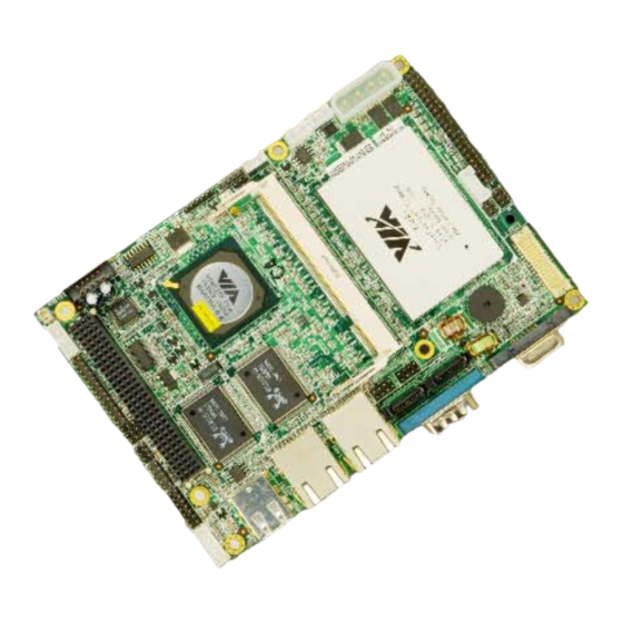
WAFER-LUKE 1.2 WAFER-LUKE Overview Figure 1-1: WAFER-LUKE Overview Page 18 IEI ® Technology, Corp. -
Page 19: Wafer-Luke Connectors
WAFER-LUKE Figure 1-2: WAFER-LUKE Solder Side 1.2.1 WAFER-LUKE Connectors The WAFER-LUKE has the following connectors on-board: 1 x +5VSB and power on connector 1 x –12V power connector 1 x 4-pin ATX power connector 1 x Audio connector 1 x CompactFlash connector... - Page 20 1 x RS-232 or RS-485 serial connector 2 x SATA connectors 2 x USB connectors for four USB 2.0 devices The WAFER-LUKE has the following connectors on the board rear panel: 2 x Ethernet connectors 1 x Serial port connector...
-
Page 21: Technical Specifications
WAFER-LUKE 1.3 Technical Specifications 1.3.1 WAFER-LUKE Specifications WAFER-LUKE technical specifications are listed in Table 1-1. Detailed descriptions of each specification can be found in Chapter 2 Detailed Specifications. Specification WAFER-LUKE Form Factor 3.5” form factor Embedded 1GHz VIA LUKE Embedded 533MHz VIA LUKE... -
Page 22: Table 1-1: Technical Specifications
WAFER-LUKE Watchdog Timer Software programmable 1-255 sec. by supper I/O Digital I/O 8-bit digital I/O, 4-bit input/4-bit output Expansion One PCI-104 Power Supply +5V or +12V AT or ATX power support Temperature 0ºC - 60ºC Humidity (operating) 5%~95% non-condensing Dimensions... -
Page 23: Detailed Specifications
WAFER-LUKE Chapter Detailed Specifications Page 23... -
Page 24: Overview
102 mm 2.3 CPU Support The WAFER-LUKE CPU card comes with a preinstalled 1GHz or 533MHz, ultra low voltage (ULV) VIA® Luke processor. The new VIA 'Luke' CoreFusion Processing Platform integrates the latest generation VIA Eden-N™ processor with the VIA CN400 Northbridge in a single, low power package. -
Page 25: System Chipset
ATA devices and the SATAlite™ interface expands support for two additional SATA devices. 2.4 System Chipset The WAFER-LUKE CPU card has a VIA VT8237R Plus Southbridge onboard. A summary of the available Southbridge features is listed below. For more information on this chipset please visit the VIA website. -
Page 26: Data Flow
WAFER-LUKE V-MAP Architecture Ultra V-Link High throughput 1GB/s South Bridge/North Bridge interconnect Supports new generation VIA North Bridges across all processor platforms 8X V-Link High speed 533MB/s South Bridge/North Bridge interconnect Supports current generation VIA North Bridges across all processor platforms... -
Page 27: Graphics Support
WAFER-LUKE 2.6 Graphics Support The LUKE processor comes with a S3 Chromotion graphics engine. The features listed below are compatible with S3 Graphics' Chrome S20 Series processors: Chromotion Video Acceleration:- WMV9 Motion Compensation H/W Acceleration – Reduces CPU utilization when decoding Windows Media Video 9 (WMV9) files. -
Page 28: Memory Support
WAFER-LUKE 2.7 Memory Support The WAFER-LUKE has one 200-pin SO-DIMM socket and supports one DDR SO-DIMM module with the following specifications: Maximum RAM: 1GB DIMM Transfer Rates: 400MHz or 333MHz 2.8 PCI Bus Interface Support The PCI bus on the WAFER-LUKE CPU card has the following features: 33MHz Revision 2.2 is implemented... -
Page 29: Drive Interfaces
2 x IDE devices 1 x CF Type I or CF Type II card 2.10.1 SATA Drives The WAFER-LUKE supports two, first generation SATA drives with transfer rates of up to 150Mb/sec. 2.10.2 IDE HDD Interfaces The WAFER-LUKE chipset IDE controller supports up to four HDDs with the following... -
Page 30: Compactflash Card Support
66MB/sec and capacities up to 137GB are supported. 2.11 Serial Ports The WAFER-LUKE has two high-speed UART serial ports. One of the serial ports is RS-232 compliant and one serial port can be configured as RS-232, RS-422, or RS-485. -
Page 31: Usb Interfaces
The WAFER-LUKE supports six USB 2.0 or USB 1.1 devices. Two are connected externally and the remaining four internally. 2.16 BIOS The WAFER-LUKE uses a licensed copy of AMI BIOS. The features of the flash BIOS used are listed below: SMIBIOS (DMI) compliant... - Page 32 WAFER-LUKE 12.288MHz BITCLK input Integrated PCBEEP generator to save buzzer Interrupt capability Three analog line-level stereo inputs with 5-bit volume control, LINE_IN, CD, High-quality differential CD input Two analog line-level mono inputs: PCBEEP, PHONE-IN Two software selectable MIC inputs Dedicated Front-MIC input for front panel applications (software selectable) Boost preamplifier for MIC input LINE input shared with surround output;...
-
Page 33: Power Consumption
WAFER-LUKE 2.19 Power Consumption Table 2-1 shows the power consumption parameters for the WAFER-LUKE-1G-R10 when a 1GHz VIA LUKE processor is mounted on the board and 1GB of 333MHz DDR SDRAM is used. Voltage Current 4.67A +12V 0.04A +5VSB 0.02A... -
Page 34: Optional Accessory Items
WAFER-LUKE 1 x RS-232/422/485 cable 1 x KB/MS cable 1 x Audio cable 1 x Mini jumper pack 1 x Utility CD 1x Quick Installation Guide 2.20.2 Optional Accessory Items The items shown in the list below are optional accessory items are purchased separately. -
Page 35: Connectors
WAFER-LUKE Chapter Connectors Page 35... -
Page 36: Peripheral Interface Connectors
3.1 Peripheral Interface Connectors Section 3.1.2 shows peripheral interface connector locations. Section 3.1.2 lists all the peripheral interface connectors seen in Section 3.1.2. 3.1.1 WAFER-LUKE Layout Figure 3-1 shows the on-board peripheral connectors, rear panel peripheral connectors and on-board jumpers. -
Page 37: Peripheral Interface Connectors
Figure 3-2: Connector and Jumper Locations (Solder Side) 3.1.2 Peripheral Interface Connectors Table 3-1 shows a list of the peripheral interface connectors on the WAFER-LUKE. Detailed descriptions of these connectors can be found in Section 3.2 on page 40. Connector... -
Page 38: External Interface Panel Connectors
8-pin header JUSB3 Table 3-1: Peripheral Interface Connectors 3.1.3 External Interface Panel Connectors Table 3-2 lists the external peripheral interface connectors on the WAFER-LUKE. Detailed descriptions of these connectors can be found in Section 0 on page 63. Connector Type... -
Page 39: On-Board Jumpers
WAFER-LUKE VGA port connector 15-pin female VGA1 Table 3-2: External peripheral interface connectors 3.1.4 On-board Jumpers NOTE: A jumper is a metal bridge that is used to close an electrical circuit. It consists of two metal pins and a small metal clip (often protected by a plastic cover) that slides over the pins to connect them. -
Page 40: Internal Peripheral Connectors
3.2 Internal Peripheral Connectors Internal peripheral connectors are found on the motherboard and are only accessible when the motherboard is outside of the chassis. This section has complete descriptions of all the internal, peripheral connectors on the WAFER-LUKE. 3.2.1 +5VSB PS_ON CN Label:... -
Page 41: 12V Power Connector
WAFER-LUKE 3.2.2 –12V Power Connector CN Label: CN Type: 3-pin header (1x3) CN Location: See Figure 3-4 CN Pinouts: See Table 3-5 The –12V power connector connects to an ATX power supply. Figure 3-4:–12V Power Connector Location PIN NO. DESCRIPTION... -
Page 42: Audio Connector
WAFER-LUKE CN Pinouts: See Table 3-6 The AT power connector is connected to an ATX power source that powers the system. Figure 3-5: AT Power Connector Location PIN NO. DESCRIPTION +12V Table 3-6: AT Power Connector Pinouts 3.2.4 Audio Connector... -
Page 43: Compactflash Connector
WAFER-LUKE Figure 3-6: Audio Connector Pinouts PIN NO. DESCRIPTION PIN NO. DESCRIPTION Line out R Line in R Line out L Line in L MIC in Table 3-7: Audio Connector Pinouts 3.2.5 CompactFlash Connector CN Label: CN Type: 50-pin header (2x25) -
Page 44: Figure 3-6: Compactflash Connector Location (Solder Side)
WAFER-LUKE Figure 3-7: CompactFlash Connector Location (Solder Side) Page 44 IEI ® Technology, Corp. -
Page 45: Table 3-8: Compactflash Connector Pinouts
WAFER-LUKE PIN NO. DESCRIPTION PIN NO. DESCRIPTION GROUND VCC-IN CHECK1 DATA 3 DATA 11 DATA 4 DATA 12 DATA 5 DATA 13 DATA 6 DATA 14 DATA 7 DATA 15 HDC_CS0# HDC_CS1 GROUND IOR# IOW# VCC_COM IRQ15 VCC_COM VCC_COM CSEL... -
Page 46: Fan Connector
WAFER-LUKE 3.2.6 Fan Connector CN Label: FAN1 CN Type: 3-pin header CN Location: See Figure 3-8 CN Pinouts: See Table 3-9 The CPU cooling fan connector provides a +5V, 500mA current to a CPU cooling fan. The connector has a "rotation" pin to get rotation signals from fans and notify the system so the system BIOS can recognize the fan speed. -
Page 47: Gpio Connector
WAFER-LUKE CN Type: 6-pin header (1x6) CN Location: See Figure 3-9 CN Pinouts: See Table 3-10 The front panel connector (CN1) connects to several external indicators to monitor the motherboard and peripheral devices. These indicators and switches include: Power LED... -
Page 48: Ide Connector
CN Type: CN Location: See Figure 3-11 CN Pinouts: See Table 3-12 One 44-pin IDE device connector on the WAFER-LUKE motherboard supports connectivity to Ultra ATA/33/66/100 IDE devices with data transfer rates up to 133MB/s. Page 48 IEI ® Technology, Corp. -
Page 49: Figure 3-10: Ide Device Connector Location
WAFER-LUKE Figure 3-11: IDE Device Connector Location PIN NO. DESCRIPTION PIN NO. DESCRIPTION RESET# GROUND DATA 7 DATA 8 DATA 6 DATA 9 DATA 5 DATA 10 DATA 4 DATA 11 DATA 3 DATA 12 DATA 2 DATA 13 Page 49... -
Page 50: Ir Interface Connector (5-Pin)
WAFER-LUKE DATA 1 DATA 14 DATA 0 DATA 15 GROUND IDE DRQ GROUND IOW# GROUND IOR# GROUND IDE CHRDY GROUND IDE DACK GROUND–DEFAULT INTERRUPT HDC CS0# HDC CS1# HDD ACTIVE# GROUND GROUND Table 3-12: Secondary IDE Connector Pinouts 3.2.10 IR Interface Connector (5-pin) -
Page 51: Inverter Power Connector
WAFER-LUKE Figure 3-12: IR Connector Pinout Locations PIN NO. DESCRIPTION CIRRX IRRX IRTX Table 3-13: IR Connector Pinouts 3.2.11 Inverter Power Connector CN Label: INV1 CN Type: 5-pin header (1x5) CN Location: See Figure 3-13 CN Pinouts: See Table 3-14 The inverter connector is connected to the LCD backlight. -
Page 52: Lcd Lvds Connector
WAFER-LUKE Figure 3-13: Inverter Connector Location PIN NO. DESCRIPTION +12V ENBLT Table 3-14: Inverter Power Connector Pinouts 3.2.12 LCD LVDS Connector CN Label: LVDS1 CN Type: 30-pin header (2x15) CN Location: See Figure 3-14 CN Pinouts: See Figure 3-14 The LVDS LCD connector (LVDS1) connects to a one or two channel (18-bit) LVDS panel. -
Page 53: Figure 3-13: Lvds Connector Locations
WAFER-LUKE Figure 3-14: LVDS Connector Locations DESCRIPTION DESCRIPTION CLK1P CLK1M CLK2P CLK2M Page 53... -
Page 54: Parallel Port Connector
WAFER-LUKE LCD_VDD LCD_VDD LCD_VDD LCD_VDD Table 3-15: LCD LVDS Connector Pinouts 3.2.13 Parallel Port Connector CN Label: LPT1 CN Type: 26-pin pin header CN Location: See Figure 3-15 CN Pinouts: See Table 3-16 The 26-pin pin header connects to a parallel port connector interface or some other parallel port device such as a printer. -
Page 55: Slot
WAFER-LUKE DATA 5 GROUND DATA 6 GROUND DATA 7 GROUND ACKNOWLEDGE GROUND BUSY GROUND PAPER EMPTY GROUND PRINTER SELECT Table 3-16: Parallel Port Connector Pinouts 3.2.14 PCI-104 Slot CN Label: PCI1 CN Type: 120-pin PCI-104 slot CN Location: See Figure 3-16... -
Page 56: Figure 3-15: Pci-104 Slot Location
WAFER-LUKE Figure 3-16: PCI-104 Slot Location Page 56 IEI ® Technology, Corp. -
Page 57: Table 3-17: Pci-104 Slot Connector Pinouts
WAFER-LUKE Pin No. Column A Column B Column C Column D GND/5V TBD1 AD00 VI/O1 AD02 AD01 AD05 AD04 AD03 C/BE0# AD07 AD06 AD09 AD08 AD11 VI/O2 AD10 M66EN AD14 AD13 AD12 +3.3V C/BE1# AD15 +3.3V SERR# SB0# PERR# +3.3V... -
Page 58: Power Switch Connector
WAFER-LUKE 3.2.15 Power Switch Connector CN Label: CN Type: 2-pin header (1x2) CN Location: See Figure 3-17 CN Pinouts: See Table 3-18 The power switch connector is connected to the reset button on the external chassis. Figure 3-17: Power Switch Connector Locations PIN NO. -
Page 59: Rs-232/422/485 Serial Port Connector
WAFER-LUKE The reset button connector is connected to the reset button on the external chassis. Figure 3-18: Reset Button Connector Locations PIN NO. DESCRIPTION RESET Table 3-19: Reset Button Connector Pinouts 3.2.17 RS-232/422/485 Serial Port Connector CN Label: COM2 14-pin header (2x7) -
Page 60: Sata Drive Connectors
WAFER-LUKE Figure 3-19: RS-232/422/485 Serial Port Connector Location PIN NO. DESCRIPTION PIN NO. DESCRIPTION NDCD2 NDSR2 NRX2 NRTS2 NTX2 NCTS2 NDTR2 VRI2 TX2+ TX2- RX2+ RX2- Table 3-20: RS-232/RS-485 Serial Port Connector Pinouts 3.2.18 SATA Drive Connectors CN Label: SATA1, SATA2... -
Page 61: Figure 3-19: Sata Drive Connector Locations
WAFER-LUKE Figure 3-20: SATA Drive Connector Locations PIN NO. DESCRIPTION Table 3-21: SATA Drive Connector Pinouts Page 61... -
Page 62: Internal Usb Connectors
WAFER-LUKE 3.2.19 Internal USB Connectors CN Label: JUSB2 and JUSB3 CN Type: 8-pin header (2x4) CN Location: See Figure 3-21 CN Pinouts: See Table 3-22 The two 2x4 USB pin connectors provide connectivity to four USB 2.0 devices. The USB ports are used for I/O bus expansion. -
Page 63: External Peripheral Interface Connectors
WAFER-LUKE 3.3 External Peripheral Interface Connectors Figure 3-22 shows the WAFER-LUKE rear panel. The external peripheral interface connectors connect to devices externally when the WAFER-LUKE is installed in a chassis. The external peripheral interface connectors are: 2 x USB connectors... -
Page 64: Serial Port Connector
D-SUB Serial Port Connector CN Location: See Figure 3-22 CN Pinouts: See Table 3-24 and Figure 3-24 The WAFER-LUKE has an RS-232 serial port on the rear panel. Figure 3-24: COM1 Serial Port Connector Page 64 IEI ® Technology, Corp. -
Page 65: Lan Connector
CN Pinouts: See Table 3-25 (RJ-45) The WAFER-LUKE is equipped with two built-in GbE Ethernet controllers. The controllers can connect to the LAN through two RJ-45 LAN connectors. There are two LEDs on the connector indicating the status of LAN. The pin assignments are listed in the following... -
Page 66: Usb Connectors
CN Location: See Figure 3-22 CN Pinouts: See Table 3-27 The WAFER-LUKE has a four rear panel USB 2.0 ports. These ports connect to both USB 2.0 and USB 1.1 devices. PIN NO. DESCRIPTION PIN NO. DESCRIPTION USBV3L 5V USBP4N... -
Page 67: Installation And Configuration
WAFER-LUKE Chapter Installation and Configuration Page 67... -
Page 68: Anti-Static Precautions
4.1 Anti-static Precautions Electrostatic discharge (ESD) can cause serious damage to electronic components, including the WAFER-LUKE. (Dry climates are especially susceptible to ESD.) It is therefore critical that whenever the WAFER-LUKE (or any other electrical component) is handled, the following anti-static precautions are strictly adhered to. -
Page 69: Unpacking
PCB circuit, connector pins, or its components. 4.3 Unpacking NOTE: If any of the items listed below are missing when the WAFER-LUKE is unpacked, do not proceed with the installation and contact the reseller or vendor Motherboard was purchased from. 4.3.1 Unpacking Precautions Some components on WAFER-LUKE are very sensitive to static electricity and can be damaged by a sudden rush of power. -
Page 70: Checklist
Handle the WAFER-LUKE by its edges. Do not touch the IC chips, leads or circuitry unneccessarily. Do not place a PCB on top of an anti-static bag. Only the inside of the bag is safe from static discharge. -
Page 71: Preinstalled Components
4.4.1 Preinstalled Components The components listed below are preinstalled on the WAFER-LUKE. CPU heat sink 4.4.2 Components to Install To install the WAFER-LUKE, the following components must be installed or connected to the WAFER-LUKE DIMM modules Peripheral devices 4.4.3 DIMM Module Installation 4.4.3.1 Purchasing the Memory Module... -
Page 72: Dimm Module Installation
WAFER-LUKE The DIMM can be either single-sided or dual-sided. 4.4.3.2 DIMM Module Installation To install the SO-DIMM module please follow the steps below. Step 1: Locate the SO-DIMM module connector. Step 2: Push the SO-DIMM chip into the socket at an angle. (See Figure 4-1) -
Page 73: Ide Disk Drive Connector (Ide1)
Table 4-1: IEI Provided Cables 4.4.4.1 IDE Disk Drive Connector (IDE1) The cable used to connect the WAFER-LUKE to the IDE HDD is a standard 44-pin ATA33 flat cable. To connect an IDE device to the WAFER-LUKE follow the instructions below. -
Page 74: Parallel Port Connector (Lpt1)
12-pin-to-phone adapter kit is required. 4.4.4.5 COM Port Connectors [COM2] The WAFER-LUKE provides two serial ports, COM1 is accessed externally and COM2 is accessed on the board. The serial ports facilitate the connection to serial devices or a communications network, e.g., terminal console. -
Page 75: Clear Cmos Jumper
Jumper Location: See Figure 4-2 If the WAFER-LUKE fails to boot due to improper BIOS settings, use this connector to clear the CMOS data and reset the system BIOS information. To do this, use the jumper cap to close pins 2 and 3 for a few seconds then reinstall the jumper clip back to pins 1 and 2. -
Page 76: Cf Card Setup
WAFER-LUKE Enter the correct CMOS setting Load Optimal Defaults Load Failsafe Defaults. After having done one of the above, save the changes and exit the CMOS Setup menu. Clear CMOS DESCRIPTION Short 1 - 2 (Default) Keep CMOS Setup Short 2 - 3... -
Page 77: Lcd Voltage Setup Jumper
WAFER-LUKE Jumper Type: 3-pin header Jumper Settings: See Table 4-4 Jumper Location: See Figure 4-3 The CF Card Setup jumper sets the compact flash card as either the slave device or the master device. DESCRIPTION Short 1-2 (Default) Slave Short 2-3... -
Page 78: Table 4-5: Lcd Voltage Setup Jumper Settings
WAFER-LUKE WARNING: Making the wrong setting on this jumper may cause irreparable damage to both the motherboard and the LCD screen connected to the onboard connector. Jumper Label: 6-pin header Jumper Type: Jumper Settings: See Table 4-5 Jumper Location: See Figure 4-4 This jumper allows the user to set the voltage for the LCD panel. -
Page 79: Rs-232/485 Setup
Jumper Location: See Figure 4-5 The WAFER-LUKE has two COM2 serial port setup jumpers. The first jumper, JP3 selects whether the serial port is RS-232 or RS-422/485. If the RS-422/485 configuration is set, the second jumper, JP4, sets the serial port as RS-422 or RS-485. -
Page 80: Com2 Voltage Setup Jumper
RS-422 Default Short Pin 2 ~ Pin 3 RS-485 Table 4-7: WAFER-LUKE COM2 Serial Port Setup (JP4) The RS-232/422/485 Setup jumper locations are shown in Figure 4-5. Figure 4-5: COM2 Setup Jumper Pinout Locations 4.5.5 COM2 Voltage Setup Jumper Jumper Label:... -
Page 81: Chassis Installation
After the DIMM modules have been installed and after the internal peripheral connectors have been connected to the peripheral devices and the jumpers have been configured, the WAFER-LUKE can be mounted into chassis. To mount a board into a chassis, please refer to the chassis user guide that came with the product. -
Page 82: External Peripheral Interface Connectors
WAFER-LUKE 4.7 External Peripheral Interface Connectors 4.7.1 LCD Panel Connection The conventional CRT monitor connector, VGA1, is a 15-pin, female D-SUB connector. Pin assignments can be seen in that can be connected to external monitors. 4.7.2 Ethernet Connection The rear panel RJ-45 connectors can be connected to an external LAN and communicate with data transfer rates up to 1Gb/s. -
Page 83: Ami Bios Setup
WAFER-LUKE Chapter AMI BIOS Setup Page 83... -
Page 84: Introduction
WAFER-LUKE 5.1 Introduction A licensed copy of AMI BIOS is preprogrammed into the ROM BIOS. The BIOS setup program allows users to modify the basic system configuration. This chapter describes how to access the BIOS setup program and the configuration options that may be changed. -
Page 85: Getting Help
WAFER-LUKE F1 key General help, only for Status Page Setup Menu and Option Page Setup Menu F2 /F3 key Change color from total 16 colors. F2 to select color forward. F10 key Save all the CMOS changes, only for Main Menu Table 5-1: BIOS Navigation Keys 5.1.3 Getting Help... -
Page 86: Main
WAFER-LUKE 5.2 Main The Main BIOS menu (BIOS Menu 1) appears when the BIOS Setup program is entered. The Main menu gives an overview of the basic system information. BIOS Menu 1: Main System Overview The System Overview lists a brief summary of different system components. The fields in System Overview cannot be changed. -
Page 87: Advanced
WAFER-LUKE Type: Names the currently installed processor Speed: Lists the processor speed Count: The number of CPUs on the motherboard System Memory: Displays the auto-detected system memory. Size: Lists memory size The System Overview field also has two user configurable fields: System Time [xx:xx:xx] Use the System Time option to set the system time. -
Page 88: Cpu Configuration
WAFER-LUKE BIOS Menu 2: Advanced 5.3.1 CPU Configuration Use the CPU Configuration menu (BIOS Menu 3) to view detailed CPU specifications and configure the CPU. Page 88 IEI ® Technology, Corp. - Page 89 WAFER-LUKE BIOS Menu 3: CPU Configuration The CPU Configuration menu (BIOS Menu 3) lists the following CPU details: Manufacturer: Lists the name of the CPU manufacturer Brand String: Lists the brand name of the CPU being used Frequency: Lists the CPU processing speed...
-
Page 90: Ide Configuration
WAFER-LUKE 5.3.2 IDE Configuration Use the IDE Configuration menu (BIOS Menu 4) to change and/or set the configuration of the IDE devices installed in the system. BIOS Menu 4: IDE Configuration OnBoard PCI IDE Controller [Both] Use the OnBoard PCI IDE Controller BIOS option to specify the IDE channels used by the onboard PCI IDE controller. -
Page 91: Ide Master, Ide Slave
WAFER-LUKE Primary Only allows the system to detect the Primary IDE channel, including both the Primary Master and the Primary Slave Secondary Only allows the system to detect the Secondary IDE channel, including both the Secondary Master and Secondary Slave... - Page 92 WAFER-LUKE BIOS Menu 5: IDE Master and IDE Slave Configuration Auto-Detected Drive Parameters The “grayed-out” items in the left frame are IDE disk drive parameters automatically detected from the firmware of the selected IDE disk drive. The drive parameters are listed as follows: Device: Lists the device type (e.g.
- Page 93 WAFER-LUKE amount of data transferred. Only 512 bytes of data can be transferred per interrupt if block mode is not used. Block mode allows transfers of up to 64 KB per interrupt. PIO Mode: Indicates the PIO mode of the installed device.
- Page 94 WAFER-LUKE Use the LBA/Large Mode option to disable or enable BIOS to auto detects LBA (Logical Block Addressing). LBA is a method of addressing data on a disk drive. In LBA mode, the maximum drive capacity is 137 GB. Disabled BIOS is prevented from using the LBA mode control on the specified channel.
- Page 95 WAFER-LUKE PIO mode 2 selected with a maximum transfer rate of 8.3MBps PIO mode 3 selected with a maximum transfer rate of 11.1MBps PIO mode 4 selected with a maximum transfer rate of 16.6MBps (This setting generally works with all hard disk drives manufactured after 1999.
- Page 96 WAFER-LUKE rate of 25MBps UDMA2 Ultra DMA mode 2 selected with a maximum data transfer rate of 33.3MBps UDMA3 Ultra DMA mode 3 selected with a maximum data transfer rate of 44MBps (To use this mode, it is required that an 80-conductor ATA cable is used.)
-
Page 97: Super Io Configuration
WAFER-LUKE 32Bit Data Transfer [Enabled] Use the 32Bit Data Transfer BIOS option to enables or disable 32-bit data transfers. Disabled Prevents the BIOS from using 32-bit data transfers. Enabled Allows BIOS to use 32-bit data transfers on supported EFAULT hard disk drives. - Page 98 WAFER-LUKE BIOS Menu 6: Super IO Configuration Serial Port1 Address [3F8/IRQ4] Use the Serial Port1 Address option to select the Serial Port 1 base address. No base address is assigned to Serial Port 1 Disabled Serial Port 1 I/O port address is 3F8 and the interrupt...
- Page 99 WAFER-LUKE IrDA Serial Port 2 mode is IrDA ASK IR Serial Port 2 mode is ASK IR Parallel Port Address [Disabled] Use the Parallel Port Address option to select the parallel port base address. Disabled No base address is assigned to the Parallel Port...
- Page 100 WAFER-LUKE system and the parallel port device and the transmission rates between the two are much faster than the Normal mode The parallel port is also be compatible with EPP devices described above Parallel Port IRQ [IRQ7] Use the Parallel Port IRQ selection to set the parallel port interrupt address.
- Page 101 WAFER-LUKE Disabled No base address is assigned to serial port 4 Serial port 4 I/O port address is 3E8 (Default) Serial port 4 I/O port address is 2E8 Serial port 4 I/O port address is 2E0 Serial Port4 IRQ [10] Use the Serial Port4 IRQ selection to set the interrupt address for serial port 4.
-
Page 102: Hardware Health Configuration
WAFER-LUKE Serial Port5 IRQ [11] Use the Serial Port5 IRQ option to select the interrupt address for serial port 5. Serial port 5 IRQ address is 10 Serial port 5 IRQ address is 11 EFAULT Serial Port6 Address [2D8] Use the Serial Port6 IRQ option to select the interrupt address for serial port 6. - Page 103 WAFER-LUKE BIOS Menu 7: Hardware Health Configuration The following system parameters and values are shown. The system parameters that are monitored are: System Temperatures: The following system temperatures are monitored CPU Temperature System Temperature Fan Speeds: The CPU cooling fan speed is monitored.
-
Page 104: Acpi Configuration
WAFER-LUKE 5.3.5 ACPI Configuration The ACPI Configuration menu (BIOS Menu 8) configures the Advanced Configuration and Power Interface (ACPI) and Power Management (APM) options. BIOS Menu 8: ACPI Configuration Page 104 IEI ® Technology, Corp. -
Page 105: Advanced Acpi Configuration
WAFER-LUKE ACPI Aware O/S [Yes] Use the ACPI Aware O/S option to enable the system to configure ACPI power saving options. ACPI can only be implemented if the system OS complies with the ACPI standard. Windows 98, Windows 2000, and Windows XP all comply with ACPI. - Page 106 WAFER-LUKE BIOS Menu 9: Advanced ACPI Configuration ACPI 2.0 Features Use the ACPI 2.0 Features option to enable the ACPI (Advanced Configuration and Power Interface) features. By enabling this feature the system RSDP (Root System Description Pointer) is able to obtain physical addresses for other 64-bit fixed system description tables.
-
Page 107: Apm Configuration
WAFER-LUKE Disabled (Default) Pointers to the AMI OEMB table are not provided in the RSDT and the XSDT Pointers to the AMI OEMB table are provided in the Enabled RSDT and the XSDT Headless Mode [Disabled] Use the Headless Mode option to update the ACPI FACP (Fixed ACPI Description Table) to indicate headless operations, i.e. - Page 108 WAFER-LUKE BIOS Menu 10:Advanced Power Management Configuration Power Management/APM [Enabled] Use the Power Management/APM BIOS option to enable access to the advanced power management features. If this option is disabled, the only other option on the screen is the Power Button Mode.
- Page 109 WAFER-LUKE On/Off (Default) When the power button is pressed the system is either turned on or off When the power button is pressed the system goes into Suspend suspend mode Restore on AC Power Loss [Power Off] Use the Restore on AC Power Loss BIOS option to specify what state the system returns to if there is a sudden loss of power to the system.
-
Page 110: Usb Configuration
WAFER-LUKE IRQ3 IRQ4 IRQ5 IRQ7 IRQ9 IRQ10 IRQ11 IRQ13 IRQ14 IRQ15 Resume on Ring [Disabled] Use the Resume on Ring BIOS option to enable activity on the RI (ring in) modem line to rouse the system from a suspend or standby state. That is, the system will be roused by an incoming call on a modem. - Page 111 WAFER-LUKE BIOS Menu 11: USB Configuration USB Configuration The USB Configuration field shows the system USB configuration. The items listed are: Module Version: x.xxxxx.xxxxx USB Devices Enabled: Lists the USB devices that are enabled on the system USB 1.1 Ports Configuration [USB 8 Ports] Use the USB Ports Configuration BIOS option to specify how many of the USB ports are USB 1.1 compatible.
- Page 112 WAFER-LUKE Disabled None of the ports are USB 1.1 compatible USB 2 Ports Two ports are USB 1.1 compatible USB 4 ports Four ports are USB 1.1 compatible USB 6 ports Six ports are USB 1.1 compatible (Default) Eight ports are USB 1.1 compatible USB 8 ports USB 2.0 Controller [Enabled]...
-
Page 113: Pci/Pnp
WAFER-LUKE support for the USB keyboard and mouse. This option is useful for Microsoft Windows NT Operating System and for multi-language keyboards. Also this option provides the PS/2 functionalities like keyboard lock, password setting, scan code selection etc to USB keyboards. - Page 114 WAFER-LUKE Page 114 IEI ® Technology, Corp.
- Page 115 WAFER-LUKE BIOS Menu 12: PCI/PnP Configuration Clear NVRAM [No] Use the Clear NVRAM option to specify if the NVRAM (Non-Volatile RAM) is cleared when the power is turned off. System does not clear NVRAM during system boot EFAULT System clears NVRAM during system boot Plug &...
- Page 116 WAFER-LUKE specifications, this option allows the BIOS to configure all the devices in the system. This setting allows the operating system to change the interrupt, I/O, and DMA settings. Set this option if the system is running Plug and Play aware operating systems.
- Page 117 WAFER-LUKE snooping to be enabled, this option should be disabled. No/Enab PCI devices are informed that an ISA based Graphics device is installed in the system so the ISA based Graphics card functions correctly. This does not necessarily indicate a physical ISA adapter card. The graphics chipset can be mounted on a PCI card.
- Page 118 WAFER-LUKE PCI IDE adapter card. Only select this slot if the adapter card is installed in PCI Slot 3. PCI Slot 4 PCI Slot 4 is selected as the location of the OffBoard PCI IDE adapter card. Only select this slot if the adapter card is installed in PCI Slot 4.
- Page 119 WAFER-LUKE IRQ 15 DMA Channel# [Available] Use the DMA Channel# option to assign a specific DMA channel to a particular PCI/PnP device. Available The specified DMA is available to be used by EFAULT PCI/PnP devices Reserved The specified DMA is reserved for use by Legacy...
-
Page 120: Boot
WAFER-LUKE 5.5 Boot Use the Boot menu (BIOS Menu 13) to configure system boot options. BIOS Menu 13: Boot Page 120 IEI ® Technology, Corp. -
Page 121: Boot Settings Configuration
WAFER-LUKE 5.5.1 Boot Settings Configuration Use the Boot Settings Configuration menu (BIOS Menu 13) to configure advanced system boot options. BIOS Menu 14: Boot Settings Configuration Quick Boot [Enabled] Use the Quick Boot BIOS option to make the computer speed up the boot process. - Page 122 WAFER-LUKE Boot From LAN Support [Disabled] Use the BOOT From LAN Support option to enable the system to be booted from a remote system. Disabled (Default) Cannot be booted from a remote system through the Enabled (Default) Can be booted from a remote system through the Quiet Boot [Disabled] Use the Quiet Boot BIOS option to select the screen display when the system boots.
- Page 123 WAFER-LUKE use the 10-keys on the keyboard, press the Number Lock key located on the upper left-hand corner of the 10-key pad. The Number Lock LED on the keyboard lights up when the Number Lock is engaged. Allows the Number Lock on the keyboard to be enabled EFAULT automatically when the computer system boots up.
-
Page 124: Boot Device Priority
WAFER-LUKE Enabled If there is an error during boot up, the system waits for a EFAULT user to press “F1” and enter the BIOS to rectify the problem. The BIOS can then be adjusted to the correct settings. Hit ‘DEL’ Message Display [Enabled] Use the Hit “DEL”... - Page 125 WAFER-LUKE BIOS Menu 15: Boot Device Priority Settings Page 125...
-
Page 126: Hard Disk Drives
WAFER-LUKE 5.5.3 Hard Disk Drives Use the Hard Disk Drives menu to specify the boot sequence of the available HDDs. When the menu is opened, the HDDs connected to the system are listed as shown below: 1st Drive [HDD: PM-(part number)]... -
Page 127: Removable Drives
WAFER-LUKE BIOS Menu 16: Hard Disk Drives 5.5.4 Removable Drives Use the Removable Drives menu (BIOS Menu 17) to specify the boot sequence of the available FDDs. When the menu is opened, the FDDs connected to the system are listed... - Page 128 WAFER-LUKE NOTE: Only the drives connected to the system are shown. For example, if only one FDD is connected only “1st Drive” is listed. The boot sequence from the available devices is selected. If the “1st Drive” option is selected a list of available FDDs is shown. Select the first FDD the system boots from. If the “1st Drive”...
-
Page 129: Cd/Dvd Drives
WAFER-LUKE 5.5.5 CD/DVD Drives Use the CD/DVD Drives menu to specify the boot sequence of the available CD/DVD drives. When the menu is opened, the CD drives and DVD drives connected to the system are listed as shown below: 1st Drive... - Page 130 WAFER-LUKE BIOS Menu 18: CD/DVD Drives Page 130 IEI ® Technology, Corp.
-
Page 131: Security
WAFER-LUKE 5.6 Security Use the Security menu (BIOS Menu 19) to set system and user passwords. BIOS Menu 19: Security Change Supervisor Password Use the Change Supervisor Password to set or change a supervisor password. The default for this option is Not Installed. If a supervisor password must be installed, select this field and enter the password. -
Page 132: Chipset
WAFER-LUKE Change User Password Use the Change User Password to set or change a user password. The default for this option is Not Installed. If a user password must be installed, select this field and enter the password. After the password has been added, Install appears next to Change User Password. - Page 133 WAFER-LUKE BIOS Menu 20: Chipset Page 133...
-
Page 134: Northbridge Via Cn400 Configuration
WAFER-LUKE 5.7.1 Northbridge VIA CN400 Configuration The Northbridge VIA CN400 Configuration menu (BIOS Menu 20) configures the Northbridge chipset. BIOS Menu 21:Northbridge Chipset Configuration The Northbridge VIA CN400 Configuration BIOS menu has three submenus DRAM Clock/Timing Configuration AGP Features Configuration... -
Page 135: Dram Clock/Timing Configurations
WAFER-LUKE 5.7.1.1 DRAM Clock/Timing Configurations The DRAM Clock/Timing Configuration menu (BIOS Menu 20) configures the DRAM settings. BIOS Menu 22: DRAM Clock/Timing Configuration DRAM Frequency [Auto] The DRAM Frequency option specifies the DRAM frequency or allows the system to automatically detect the DRAM frequency. - Page 136 WAFER-LUKE 333MHz Sets the DRAM frequency to 333MHz Auto (Default) Automatically selects the DRAM frequency DRAM Timing by SPD [Auto by SPD] The Configure DRAM Timing by SPD determines if the system uses the SPD (Serial Presence Detect) EEPROM to configure the DRAM timing. The SPD EEPROM contains...
-
Page 137: Agp Features Configuration
WAFER-LUKE 1T Command 5.7.1.2 AGP Features Configuration The AGP Features Configuration menu (BIOS Menu 20) configures the AGP settings. BIOS Menu 23: AGP Features Configuration Primary Graphics Adapter [AGP] The Primary Graphics Adapter selects the graphics adapter the system uses. -
Page 138: V-Link Features Configuration
WAFER-LUKE VGA Frame Buffer Size [64MB] The VGA Frame Buffer Size BIOS option sets the memory buffer size for the VGA display. The following buffer sizes can be set: None 16MB 32MB 64MB Panel Type [07] The Panel Type option specifies the device the panel type. The user is prompted to enter number between 0 and 15. -
Page 139: Southbridge Configuration
WAFER-LUKE V-Link Mode Selection [Auto] The V-Link Mode Selection controls V-Link bus operation. The following options are available. Auto Mode 0 Mode 1 Mode 2 Mode 3 Mode 4 V-Link Data 8X Supported [Disabled] The V-Link Data 8X Support controls the data transmission speed between the Northbridge and Southbridge chipsets. - Page 140 WAFER-LUKE BIOS Menu 25:SouthBridge Chipset Configuration Onboard SATA-IDE Use the Onboard SATA-IDE option to set the onboard SATA controller The onboard SATA controller is disabled Disabled EFAULT Native Mode The SATA controller is set as an IDE device with an...
-
Page 141: Exit
WAFER-LUKE Disabled The onboard AC’97 is disabled Enabled (Default) The onboard AC’97 automatically detected and enabled Spread Spectrum [Disabled] Use the Spread Spectrum option to reduce the EMI. Excess EMI is generated when the system clock generator pulses have extreme values. Spreading the pulse spectrum modulates changes in the extreme values from spikes to flat curves, thus reducing the EMI. - Page 142 WAFER-LUKE Use the Exit menu (BIOS Menu 26) to load default BIOS values, optimal failsafe values and to save configuration changes. BIOS Menu 26:Exit Save Changes and Exit Use the Save Changes and Exit option to save the changes made to the BIOS options and to exit the BIOS configuration setup program.
- Page 143 WAFER-LUKE Use the Discard Changes option to discard the changes and remain in the BIOS configuration setup program. Load Optimal Defaults Use the Load Optimal Defaults option to load the optimal default values for each of the parameters on the Setup menus. F9 key can be used for this operation.
- Page 144 WAFER-LUKE THIS PAGE IS INTENTIONALLY LEFT BLANK Page 144 IEI ® Technology, Corp.
-
Page 145: Software Drivers
WAFER-LUKE Chapter Software Drivers Page 145... -
Page 146: Available Software Drivers
Visit the IEI website or contact technical support for the latest updates. The WAFER-LUKE board has a number of software drivers. All the drivers can be found on the CD that came with the WAFER-LUKE. To install the drivers please follow the instructions in the sections below 6.2 Connecting a CD Drive... -
Page 147: Figure 6-1: Access The Wafer-Luke Drivers
WAFER-LUKE Figure 6-1: Access the WAFER-LUKE Drivers Step 3: Select the “VIA 4 in 1” option shown in Figure 6-2. Page 147... -
Page 148: Figure 6-2: Setup Utility Icon
WAFER-LUKE Figure 6-2: Setup Utility Icon Step 4: Select the “4 in 1” icon shown in Figure 6-3. Page 148 IEI ® Technology, Corp. -
Page 149: Figure 6-3: 4 In 1 Icon
WAFER-LUKE Figure 6-3: 4 in 1 Icon Step 5: The installation program begins to initialize. After the initialization process a welcome screen shown in Figure 6-4 appears. Click “N ” to continue the installation. Page 149... -
Page 150: Figure 6-4: Via Chipset Driver Installation Welcome Screen
WAFER-LUKE Figure 6-4: VIA Chipset Driver Installation Welcome Screen Step 6: The “Readme” in Figure 6-5 appears. Click “N ” to continue the installation. Page 150 IEI ® Technology, Corp. -
Page 151: Figure 6-5: Readme Information
WAFER-LUKE Figure 6-5: Readme Information Step 7: The user is then prompted to select the installation type. A user can select “Normal Installation” or “Quick Installation.” (See Figure 6-6) Select the installation type and click “N ” to continue the installation. -
Page 152: Figure 6-6: Via Chipset Driver Installation Type
WAFER-LUKE Figure 6-6: VIA Chipset Driver Installation Type Step 8: The setup then prompts the user (see Figure 6-7) to select the drivers that must be installed on the system. There are three drivers: VIA PCI IDE Bus Driver AGP Driver (AGP3.0 Supported) VIA INF Driver 2.20A... -
Page 153: Figure 6-7: Driver Selection
WAFER-LUKE Figure 6-7: Driver Selection Step 9: The setup then prompts the user (see Figure 6-8) if the VIA PCI IDE Bus Driver must be installed on the system. Select install or uninstall. Click “N ” to continue the installation. -
Page 154: Figure 6-8: Via Pci Ide Bus Driver Selection
WAFER-LUKE Figure 6-8: VIA PCI IDE Bus Driver Selection Step 10: In a similar way users are prompted to select if the AGP driver and the IDE driver must be installed. If these drivers must be installed, then select the driver and click “Next.”... -
Page 155: Realtek Audio Driver Installation
Figure 6-9: Restart the Computer 6.4 RealTek Audio Driver Installation To install the RealTek LAN driver, please follow the steps below: Step 1: Insert the CD into the system that contains the WAFER-LUKE board. Step 2: Select “WAFER-LUKE”. (See Figure 6-22) Page 155... -
Page 156: Figure 6-10: Access The Wafer-Luke Drivers
WAFER-LUKE Figure 6-10: Access the WAFER-LUKE Drivers Step 3: Select the “LAN” option shown in Figure 6-11. Figure 6-11: Select Audio Step 4: Select the “RealTek” icon shown in Figure 6-12. Page 156 IEI ® Technology, Corp. -
Page 157: Figure 6-12: Realtek
WAFER-LUKE Figure 6-12: RealTek Step 5: Select the ALC655 Icon shown in Figure 6-13. Page 157... -
Page 158: Figure 6-13: Alc655 Icon
WAFER-LUKE Figure 6-13: ALC655 Icon Step 6: Select the WDM_A391 icon shown in Figure 6-14. Page 158 IEI ® Technology, Corp. -
Page 159: Figure 6-14: Audio Setup Icon
WAFER-LUKE Figure 6-14: Audio Setup Icon Step 7: Once the double click the Setup icon is clicked, the install shield wizard for the audio driver starts. See Figure 6-15. Figure 6-15: Audio Driver Install Shield Wizard Starting Step 8: The RealTek Audio Setup prepares the install shield to guide you through the rest of the setup process. -
Page 160: Figure 6-16: Audio Driver Setup Preparation
WAFER-LUKE Figure 6-16: Audio Driver Setup Preparation Step 9: After install shield is prepared, the welcome screen shown in Figure 6-17 appears. To continue the installation process, click the “N ” button. The install shield starts to configure the new software as shown in Figure 6-18. -
Page 161: Figure 6-17: Audio Driver Welcome Screen
WAFER-LUKE Figure 6-17: Audio Driver Welcome Screen Figure 6-18: Audio Driver Software Configuration Step 10: At this stage the “Digital Signal Not Found” screen shown in Figure 6-19 Page 161... -
Page 162: Figure 6-19: Audio Driver Digital Signal
WAFER-LUKE appears. To continue the installation process, click the “Y ” button. The installation notice shown below appears. Figure 6-19: Audio Driver Digital Signal Step 11: At this stage the clicking the “Y ” button in Figure 6-19 appears, the installation of the driver begins. -
Page 163: Figure 6-20: Audio Driver Installation Begins
WAFER-LUKE Figure 6-20: Audio Driver Installation Begins Step 12: After the driver installation process is complete, a confirmation screen shown in Figure 6-21 appears Page 163... -
Page 164: Lan Driver Installation
INISH 6.5 LAN Driver Installation To install the RealTek AC’97 Audio driver, please follow the steps below: Step 1: Insert the CD into the system that contains the WAFER-LUKE board. Step 2: Select “WAFER-LUKE”. (See Figure 6-10) Page 164 IEI ® Technology, Corp. -
Page 165: Figure 6-22: Access The Wafer-Luke Drivers
WAFER-LUKE Figure 6-22: Access the WAFER-LUKE Drivers Step 3: Select “LAN” in the driver selection screen. See Figure 6-23. Page 165... -
Page 166: Figure 6-23: Lan Driver Menu Option
WAFER-LUKE Figure 6-23: LAN Driver Menu Option Step 4: Select the icon for the OS used in the system. See Figure 6-24. Page 166 IEI ® Technology, Corp. -
Page 167: Figure 6-24: Os Icon
WAFER-LUKE Figure 6-24: OS Icon Step 5: Select the RealTek Setup Icon shown in Figure 6-25. Page 167... -
Page 168: Figure 6-25: Realtek Setup Icon
WAFER-LUKE Figure 6-25: RealTek Setup Icon Step 6: Select the Setup icon shown in Figure 6-26. Page 168 IEI ® Technology, Corp. -
Page 169: Figure 6-26: Lan Setup Icon
WAFER-LUKE Figure 6-26: LAN Setup Icon Step 7: The welcome screen appears. Click “Next” to continue. See Figure 6-27. Page 169... -
Page 170: Figure 6-27: Lan Welcome Screen
WAFER-LUKE Figure 6-27: LAN Welcome Screen Step 8: The program is initialized and the Install window appears. Click “Install” to continue the installation process. See Figure 6-28. Page 170 IEI ® Technology, Corp. -
Page 171: Figure 6-28: Install Lan
WAFER-LUKE Figure 6-28: Install LAN Step 9: The driver is installed. See Figure 6-29. Page 171... - Page 172 WAFER-LUKE Figure 6-29: LAN Driver Installation Step 10: The completed installation screen appears. Click “Finish” to exit the program. See Figure 6-30. Step 0: Page 172 IEI ® Technology, Corp.
- Page 173 WAFER-LUKE Figure 6-30: Exit LAN Driver Setup Page 173...
- Page 174 WAFER-LUKE THIS PAGE IS INTENTIONALLY LEFT BLANK Page 174 IEI ® Technology, Corp.
-
Page 175: Abios Configuration Options
WAFER-LUKE Appendix BIOS Configuration Options Page 175... -
Page 176: Bios Configuration Options
WAFER-LUKE A.1 BIOS Configuration Options Below is a list of BIOS configuration options described in Chapter 5. System Overview ....................86 System Time [xx:xx:xx] ..................87 System Date [xx/xx/xx] ..................87 OnBoard PCI IDE Controller [Both]..............90 IDE Master and IDE Slave ..................91 Auto-Detected Drive Parameters................92 Type [Auto] ....................93... - Page 177 WAFER-LUKE Serial Port6 IRQ [10] ................... 102 ACPI Aware O/S [Yes] ..................105 ACPI 2.0 Features ....................106 ACPI APIC Support [Enabled] ................106 AMI OEMB table [Enabled]................. 106 Headless Mode [Disabled] ................. 107 Power Management/APM [Enabled]..............108 Power Button Mode [On/Off] ................108 Restore on AC Power Loss [Power Off] ............
- Page 178 WAFER-LUKE Quiet Boot [Disabled] ..................122 AddOn ROM Display Mode [Force BIOS] ............122 Bootup Num-Lock [On] ..................122 PS/2 Mouse Support [Enabled] ................. 123 Wait For ‘F1’ If Error [Enabled]................123 Hit ‘DEL’ Message Display [Enabled] ............... 124 Interrupt 19 Capture [Disabled] ................. 124 Change Supervisor Password................
-
Page 179: Bwatchdog Timer
WAFER-LUKE Appendix Watchdog Timer Page 179... - Page 180 WAFER-LUKE NOTE: The following discussion applies to DOS environment. IEI support is contacted or the IEI website visited for specific drivers for more sophisticated operating systems, e.g., Windows and Linux. The Watchdog Timer is provided to ensure that standalone systems can always recover from catastrophic conditions that cause the CPU to crash.
- Page 181 WAFER-LUKE NOTE: When exiting a program it is necessary to disable the Watchdog Timer, otherwise the system resets. Example program: ; INITIAL TIMER PERIOD COUNTER W_LOOP: AX, 6F02H ;setting the time-out value BL, 30 ;time-out value is 48 seconds ; ADD THE APPLICATION PROGRAM HERE EXIT_AP, 1 ;is the application over?
- Page 182 WAFER-LUKE THIS PAGE IS INTENTIONALLY LEFT BLANK Page 182 IEI ® Technology, Corp.
-
Page 183: Caddress Mapping
WAFER-LUKE Appendix Address Mapping Page 183... -
Page 184: Io Address Map
WAFER-LUKE C.1 IO Address Map I/O address Description Range 000-01F DMA Controller 020-021 Interrupt Controller 040-043 System time 060-06F Keyboard Controller 070-07F System CMOS/Real time Clock 080-09F DMA Controller 0A0-0A1 Interrupt Controller 0C0-0DF DMA Controller 0F0-0FF Numeric data processor 1F0-1F7... -
Page 185: Irq Mapping Table
WAFER-LUKE C.3 IRQ Mapping Table IRQ0 System Timer IRQ8 RTC clock IRQ1 Keyboard IRQ9 ACPI IRQ2 Available IRQ10 IRQ3 COM2 IRQ11 LAN/USB2.0/SATA IRQ4 COM1 IRQ12 PS/2 mouse IRQ5 SMBus Controller IRQ13 IRQ6 IRQ14 Primary IDE IRQ7 Available IRQ15 Secondary IDE Table C-3: IRQ Mapping Table C.4 DMA Channel Assignments... - Page 186 WAFER-LUKE THIS PAGE IS INTENTIONALLY LEFT BLANK Page 186 IEI ® Technology, Corp.
-
Page 187: Dexternal Ac'97 Audio Codec
WAFER-LUKE Appendix External AC’97 Audio CODEC Page 187... -
Page 188: Introduction
WAFER-LUKE D.1 Introduction The motherboard comes with an on-board Realtek ALC655 CODEC. Realtek ALC655 is a 16-bit, full duplex AC’97 Rev. 2.3 compatible audio CODECwith a sampling rate of 48KHz. D.1.1 Accessing the AC’97 CODEC The CODEC is accessed through a connector on the WAFER-LUKEG motherboard. -
Page 189: Sound Effect Configuration
WAFER-LUKE D.2 Sound Effect Configuration D.2.1 Accessing the Sound Effects Manager To access the Sound Effects Manager, please do the following: Step 1: Install the audio CODEC driver. Step 2: Click either: The Sound Effect Manager icon in the Notification Area of the system task bar (see FigureeD-2), or The Sound Effect Manager icon in the Control Panel (FigureeD-3). -
Page 190: Sound Effect Manager Configuration Options
WAFER-LUKE FigureeD-4: Sound Effects Manager (ALC655) NOTE: The Sound Effect Manager shown is for the RealTek ALC655 audio CODEC. Different CODECs may have different sound manager appearances. The following section describes the different configuration options in the Sound Effect Manager. - Page 191 WAFER-LUKE NOTE: The Karaoke Mode is configured in the Sound Effect menu. To access Karaoke configuration settings, click on the Sound Effect menu tab. Sound Effect Karaoke Mode Equalizer Speaker Configuration Speaker Test S/PDIF-In S/PDIF-Out Connector Sensing HRTF Demo Microphone Effect...
- Page 192 WAFER-LUKE that fits a certain vocal range. Equalizer Selection:- Preset equalizer settings enable easy audio range settings. Ten frequency bands can be configured. Speaker Configuration:- Multi-channel speaker settings are configured in this menu. Configurable options include: Headphone Channel mode for stereo speaker output Channel mode for 4 speaker output Channel mode for 5.1 speaker output...
-
Page 193: Evia Raid
WAFER-LUKE Appendix VIA RAID Page 193... -
Page 194: Introduction
WAFER-LUKE E.1 Introduction The VIA SATA RAID can control serial ATA (SATA) disks. VIA RAID is cost-effective RAID functionality that can increase the data read/write speed and provide protection to data by distributing mirrored duplicates of data onto two disk drives (RAID 1). -
Page 195: Features And Benefits
WAFER-LUKE E.2 Features and Benefits Supports RAID levels 0, 1, and JBOD Supports connectivity to two disk drives Supported Operating Systems include: Windows 98/Me, Windows 2000 and Windows XP Windows-based software for RAID management E.3 Installing the RAID Controller To install the RAID controller using Windows or a later OS, please follow the steps below. -
Page 196: Raid Tool Access
WAFER-LUKE E.4 RAID Tool Access To understand how to use the RAID tool please access the RAID HTML help file from the CD drive that came with the system. Insert the CD into the system and access the following directory. -
Page 197: Findex
WAFER-LUKE Index Page 197... - Page 198 WAFER-LUKE COM2 voltage setup, 82 cooling fanconnector, 47 12V power connector, 19, 42 CPU cooling fan, 105 24-pin microATX power connector, 19 data flow, 26 dimensions, 24 DIMM module, 73 5.25” form factor, 17 DIMM modules, 73, 83 drive interfaces, 29 Dual-independent display, 17 AC’97 Audio signals, 76...
- Page 199 WAFER-LUKE IDE connector, 19 PCI-104 expansion slot, 20 IDE controller, 29 PCI-104 slot, 56 IDE device, 75 peripheral connectors, 36, 83 IDE device connector, 49 peripheral devices, 74, 83 infrared, 51 Peripheral devices, 73 infrared connector, 19 PIO IDE, 29...
- Page 200 WAFER-LUKE SO-DIMM, 74 ULV, 24 SO-DIMM module, 74 Unpacking, 71 SO-DIMM socket, 28 USB 1.1, 31 software drivers, 148 USB 2.0, 17, 31 USB CD drive, 148 USB connectors, 20, 64, 84 technical specifications, 21 USB pin connectors, 63 UART serial ports, 30...
Need help?
Do you have a question about the WAFER-LUKE and is the answer not in the manual?
Questions and answers