Sign In
Upload
Manuals
Brands
IEI Technology Manuals
Motherboard
WAFER-LUKE
IEI Technology WAFER-LUKE Manuals
Manuals and User Guides for IEI Technology WAFER-LUKE. We have
1
IEI Technology WAFER-LUKE manual available for free PDF download: User Manual
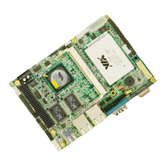
IEI Technology WAFER-LUKE User Manual (200 pages)
VIA LUKE LVDS 3.5" Low Power/Thermal Motherboard With Dual SATA, CF II RAID Support and PCI-104
Brand:
IEI Technology
| Category:
Motherboard
| Size: 9.8 MB
Table of Contents
Table of Contents
3
1 Introduction
15
Wafer-Luke Overview
16
WAFER-LUKE Models
16
WAFER-LUKE Applications
16
WAFER-LUKE Benefits
17
WAFER-LUKE Features
17
Wafer-Luke Overview
18
Figure 1-1: WAFER-LUKE Overview
18
Figure 1-1: WAFER-LUKE Solder Side
19
WAFER-LUKE Connectors
19
Technical Specifications
21
WAFER-LUKE Specifications
21
Table 1-1: Technical Specifications
22
2 Detailed Specifications
23
Overview
24
Dimensions
24
Cpu Support
24
System Chipset
25
Data Flow
26
Figure 2-1: Data Flow Block Diagram
26
Graphics Support
27
Memory Support
28
Pci Bus Interface Support
28
Ethernet Controller Specifications
28
Ethernet Controller Overview
28
Features
28
Drive Interfaces
29
SATA Drives
29
IDE HDD Interfaces
29
Compactflash Card Support
30
Serial Ports
30
Real Time Clock
30
System Monitoring
30
Infrared Data Association (Irda) Interface
30
Usb Interfaces
31
Bios
31
Control
31
Audio Codec
31
Power Consumption
33
Packaged Contents and Optional Accessory Items
33
Package Contents
33
Table 2-1: Power Consumption 1
33
Table 2-2: Power Consumption 2
33
Optional Accessory Items
34
3 Connectors
35
Peripheral Interface Connectors
36
WAFER-LUKE Layout
36
Figure 3-1: Connector and Jumper Locations
36
Peripheral Interface Connectors
37
Figure 3-1: Connector and Jumper Locations (Solder Side)
37
External Interface Panel Connectors
38
Table 3-1: Peripheral Interface Connectors
38
On-Board Jumpers
39
Table 3-2: External Peripheral Interface Connectors
39
Table 3-3: On-Board Jumpers
39
Internal Peripheral Connectors
40
5Vsb Ps_On
40
Figure 3-2: +5VSB PS_ON Connector Location
40
Table 3-4: +5VSB PS_ON Connector Pinouts
40
12V Power Connector
41
AT Power Connector
41
Figure 3-3:-12V Power Connector Location
41
Table 3-5: -12V Power Connector Pinouts
41
Audio Connector
42
Figure 3-4: at Power Connector Location
42
Table 3-6: at Power Connector Pinouts
42
Compactflash Connector
43
Figure 3-5: Audio Connector Pinouts
43
Table 3-7: Audio Connector Pinouts
43
Figure 3-6: Compactflash Connector Location (Solder Side)
44
Table 3-8: Compactflash Connector Pinouts
45
Fan Connector
46
Front Panel Connector (6-Pin)
46
Figure 3-7: Fan Connector Location
46
Table 3-9: Fan Connector Pinouts
46
GPIO Connector
47
Figure 3-8: Front Panel Connector Pinout Locations
47
Table 3-10: Front Panel Connector Pinouts
47
IDE Connector
48
Figure 3-9: GPIO Connector Location
48
Table 3-11: GPIO Connector Pinouts
48
Figure 3-10: IDE Device Connector Location
49
IR Interface Connector (5-Pin)
50
Table 3-12: Secondary IDE Connector Pinouts
50
Inverter Power Connector
51
Figure 3-11: IR Connector Pinout Locations
51
Table 3-13: IR Connector Pinouts
51
LCD LVDS Connector
52
Figure 3-12: Inverter Connector Location
52
Table 3-14: Inverter Power Connector Pinouts
52
Figure 3-13: LVDS Connector Locations
53
Parallel Port Connector
54
Figure 3-14: Parallel Port Connector Location
54
Table 3-15: LCD LVDS Connector Pinouts
54
Slot
55
Table 3-16: Parallel Port Connector Pinouts
55
Figure 3-15: PCI-104 Slot Location
56
Table 3-17: PCI-104 Slot Connector Pinouts
57
Power Switch Connector
58
Reset Button Connector
58
Figure 3-16: Power Switch Connector Locations
58
Table 3-18: Power Switch Connector Pinouts
58
RS-232/422/485 Serial Port Connector
59
Figure 3-17: Reset Button Connector Locations
59
Table 3-19: Reset Button Connector Pinouts
59
SATA Drive Connectors
60
Figure 3-18: RS-232/422/485 Serial Port Connector Location
60
Table 3-20: RS-232/RS-485 Serial Port Connector Pinouts
60
Figure 3-19: SATA Drive Connector Locations
61
Table 3-21: SATA Drive Connector Pinouts
61
Internal USB Connectors
62
Figure 3-20: USB Connector Pinout Locations
62
Table 3-22: USB Port Connector Pinouts
62
External Peripheral Interface Connectors
63
VGA Connector
63
Figure 3-21: WAFER-LUKE CP Rear Panel
63
Figure 3-22: VGA Connector
63
Serial Port Connector
64
Figure 3-23: COM1 Serial Port Connector
64
Table 3-23: VGA Connector Pinouts
64
LAN Connector
65
Table 3-24: COM1 Pinouts
65
Table 3-25: LAN Pinouts
65
USB Connectors
66
Figure 3-24: RJ-45 Ethernet Connector
66
Table 3-26: RJ-45 Ethernet Connector Leds
66
Table 3-27: USB Port Pinouts
66
4 Installation and Configuration
67
Anti-Static Precautions
68
Installation Considerations
68
Installation Notices
68
Unpacking
69
Unpacking Precautions
69
Checklist
70
Wafer-Luke Motherboard Installation
70
Preinstalled Components
71
Components to Install
71
DIMM Module Installation
71
Purchasing the Memory Module
71
DIMM Module Installation
72
Peripheral Device Connection
72
Figure 4-3: SO-DIMM Module Installation
72
Compactflash Connector
73
IDE Disk Drive Connector (IDE1)
73
Table 4-1: IEI Provided Cables
73
Audio Interface
74
COM Port Connectors [COM2]
74
Parallel Port Connector (LPT1)
74
Jumper Settings
74
Clear CMOS Jumper
75
Table 4-2: Jumpers
75
CF Card Setup
76
Figure 4-5: Clear CMOS Jumper
76
Table 4-3: Clear CMOS Jumper Settings
76
LCD Voltage Setup Jumper
77
Figure 4-6: CF Card Setup Jumper Pinout Locations
77
Table 4-4: CF Card Setup Jumper Settings
77
Table 4-5: LCD Voltage Setup Jumper Settings
78
RS-232/485 Setup
79
Figure 4-7: LCD Voltage Setup Jumper Pinout Locations
79
Table 3-19: WAFER-LUKE COM2 Serial Port Setup (JP3)
79
COM2 Voltage Setup Jumper
80
Figure 4-8: COM2 Setup Jumper Pinout Locations
80
Table 3-20: WAFER-LUKE COM2 Serial Port Setup (JP4)
80
Chassis Installation
81
Figure 4-10: COM2 Voltage Setup Jumper Pinout Locations
81
Table 4-8: COM2 Voltage Setup Jumper Settings
81
External Peripheral Interface Connectors
82
LCD Panel Connection
82
Ethernet Connection
82
USB Connection
82
Serial Connection
82
5 Ami Bios Setup
83
Introduction
84
Starting Setup
84
Using Setup
84
Getting Help
85
Unable to Reboot after Configuration Changes
85
BIOS Menu Bar
85
Table 5-1: BIOS Navigation Keys
85
Main
86
Advanced
87
CPU Configuration
88
IDE Configuration
90
IDE Master, IDE Slave
91
Super IO Configuration
97
Hardware Health Configuration
102
ACPI Configuration
104
Advanced ACPI Configuration
105
APM Configuration
107
USB Configuration
110
Pci/Pnp
113
Boot
120
Boot Settings Configuration
121
Boot Device Priority
124
Hard Disk Drives
126
Removable Drives
127
CD/DVD Drives
129
Security
131
Chipset
132
Northbridge VIA CN400 Configuration
134
DRAM Clock/Timing Configurations
135
AGP Features Configuration
137
V-Link Features Configuration
138
Southbridge Configuration
139
Exit
141
6 Software Drivers
145
Available Software Drivers
146
Connecting Acd Drive
146
4-In-1 Driver Installation
146
Figure 6-1: Access the WAFER-LUKE Drivers
147
Figure 6-2: Setup Utility Icon
148
Figure 6-3: 4 in 1 Icon
149
Figure 6-4: VIA Chipset Driver Installation Welcome Screen
150
Figure 6-5: Readme Information
151
Figure 6-6: VIA Chipset Driver Installation Type
152
Figure 6-7: Driver Selection
153
Figure 6-8: VIA PCI IDE Bus Driver Selection
154
Realtek Audio Driver Installation
155
Figure 6-9: Restart the Computer
155
Figure 6-10: Access the WAFER-LUKE Drivers
156
Figure 6-11: Select Audio
156
Figure 6-12: Realtek
157
Figure 6-13: ALC655 Icon
158
Figure 6-14: Audio Setup Icon
159
Figure 6-15: Audio Driver Install Shield Wizard Starting
159
Figure 6-16: Audio Driver Setup Preparation
160
Figure 6-17: Audio Driver Welcome Screen
161
Figure 6-18: Audio Driver Software Configuration
161
Figure 6-19: Audio Driver Digital Signal
162
Figure 6-20: Audio Driver Installation Begins
163
Lan Driver Installation
164
Figure 6-21: Audio Driver Installation Complete
164
Figure 6-22: Access the WAFER-LUKE Drivers
165
Figure 6-23: LAN Driver Menu Option
166
Figure 6-24: os Icon
167
Figure 6-25: Realtek Setup Icon
168
Figure 6-26: LAN Setup Icon
169
Figure 6-27: LAN Welcome Screen
170
Figure 6-28: Install LAN
171
Abios Configuration Options
175
Bios Configuration Options
176
Bwatchdog Timer
179
Caddress Mapping
183
Io Address Map
184
St Mb Memory Address Map
184
Irq Mapping Table
185
Dma Channel
185
Dexternal Ac'97 Audio Codec
187
Introduction
188
Accessing the AC'97 CODEC
188
Driver Installation
188
Sound Effect Configuration
189
Accessing the Sound Effects Manager
189
Sound Effect Manager Configuration Options
190
Evia Raid
193
Introduction
194
Precautions
194
Features and Benefits
195
Installing the Raid Controller
195
Raid Tool Access
196
Findex
197
Advertisement
Advertisement
Related Products
IEI Technology WAFER-LX
IEI Technology WAFER-LX3
IEI Technology WAFER-LX2-800
IEI Technology WAFER-LX-800-R12
IEI Technology WAFER-LX-WINXPE
IEI Technology WAFER-LX-CENET050
IEI Technology WAFER-LX-CLIENT-XPE
IEI Technology WAFER-LX-800-R10
IEI Technology WAFER-LX Series
IEI Technology WAFER-LX3-800
IEI Technology Categories
Motherboard
Touch Panel
Computer Hardware
Single board computers
Desktop
More IEI Technology Manuals
Login
Sign In
OR
Sign in with Facebook
Sign in with Google
Upload manual
Upload from disk
Upload from URL