Advertisement
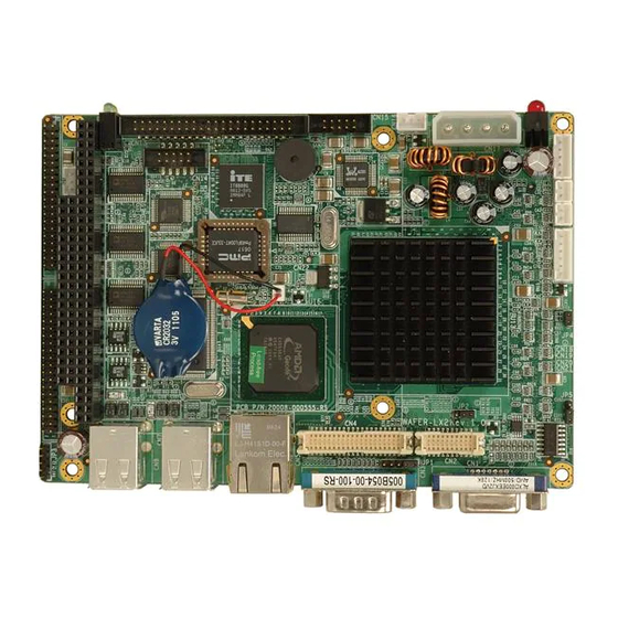
3.5" SBC with AMD Geode™ LX800 onboard Processor, 8
COM, DDR 400MHz, VGA/LCD/LVDS display, 4 x USB2.0
Quick Installation Guide
Package Contents
WAFER-LX2-800 package includes the following items:
1 x WAFER-LX2-800 Single Board Computer
1 x Audio Cable
1 x IDE Flat Cable 44p/44p
2 x 4 RS-232 Adapter Cable
1 x Mini Jumper Pack
1 x Utility CD
1 x QIG (Quick Installation Guide)
WAFER-LX2-800
Version 1.1
June. 02, 2008
©2006 Copyright by IEI Technology corp.
All rights reserved.
1
Advertisement
Table of Contents

Subscribe to Our Youtube Channel
Related Manuals for IEI Technology WAFER-LX2-800


Summary of Contents for IEI Technology WAFER-LX2-800
- Page 1 WAFER-LX2-800 Quick Installation Guide Version 1.1 June. 02, 2008 Package Contents WAFER-LX2-800 package includes the following items: 1 x WAFER-LX2-800 Single Board Computer 1 x Audio Cable 1 x IDE Flat Cable 44p/44p 2 x 4 RS-232 Adapter Cable 1 x Mini Jumper Pack...
-
Page 2: Specifications
Specifications CPU: On board AMD Geode™ LX800 500MHz processor System Chipset: AMD Geode™ LX800 + CS5536 BIOS: Award BIOS System Memory: 1 x 200-pin 400/333MHz DDR SDRAM SO-DIMM Supported (System max. 1GB) Ethernet: 10/100Mbps Single Realtek RTL8100C Ethernet chipsets I/O Interface: 4 x USB 2.0 7 x RS-232 1 x RS-232/422/485... -
Page 3: Ordering Information
Ordering Information WAFER-LX2-800-R11 3.5” SBC with AMD Geode™ LX800 onboard Processor, 8 COM, DDR 400MHz, VGA/LCD/LVDS display, 4 x USB2.0 IO-KIT-4COM-R10 4 COM Ports Adapter Board WAFER-LX2-XPE Windows® XP Embedded Image & SLD S/W CD, Licensed Sticker (w/o CPU board) - Page 4 CN2: TFT LCD LVDS Output Connector (DF14 20pin) Description Description CLK- CLK+ LCD_VCC LCD_VCC LCD_VCC LCD_VCC CN4: TFT LCD TTL Output Connector (DF13 40pin) Description Description LCD_VCC LCD_VCC LCD_VCC LCD_VCC VSYNC HSYNC LCD_EN DISP_EN CN14: DIO (GPIO) Connector (Pin-Header 5x2 2.0mm) Description Description...
- Page 5 CN15: Audio Connector (Box-Header 5x2 2.0mm) Description Description LINE_OUT-R LINE_IN-R LINE_OUT-L LINE_IN-L MIC-IN CN9: COM2 – COM4 40pin 2.0mm Connector (Box-Header 40pin 2.0mm) COM2 is multi-function port, support RS232, RS422, RS485 Selected by JP3 Description Description TXD485- TXD485+ RXD485+ RXD485- DCD2# DSR2# RXD2...
- Page 6 CN18: LCD Invert Connector CN20: Reset Button (Wafer 5pin 2.0mm) Connector (Wafer 2pin 2.0mm) Description Description BL_ADJ (Def: GND) RESET# +12V BL_EN CN13: IDE 44pin 2.0mm Connector (Box-header 44pin 2.0mm) Pin Description Pin Description CN17: Main Power Input RESET# Connector (Wafer 4pin 5.08mm) Description +12V...
- Page 7 CN11: COM5 – COM8 40pin 2.0mm Connector (Box-Header 40pin 2.0mm) Description Description DCD5# DSR5# RXD5 RTS5# TXD5 CTS5# DTR5# RI5# DCD6# DSR6# RXD6 RTS6# TXD6 CTS6# DTR6# RI6# DCD7# DSR7# RXD7 RTS7# TXD7 CTS7# DTR7# RI7# DCD8# DSR8# RXD8 RTS8# TXD8 CTS8# DTR8#...
- Page 8 CN10: PC/104 (64 pin ISA bus) Connector PIN DESCRIPTION PIN DESCRIPTION PIN DESCRIPTION PIN DESCRIPTION -IOCHK SA14 -DACK1 SA13 RSTDRV DRQ1 SA12 -REFRESH SA11 IRQ9 BCLK SA10 IRQ7 DRQ2 IRQ6 IRQ5 -NOWS IRQ4 +12V IRQ3 IOCHRDY -DACK2 -SMEMW SA19 -SMEMR BALE SA18 -IOW...
-
Page 9: Board Layout: Jumper And Connector Locations
Board Layout: Jumper and Connector Locations...
Need help?
Do you have a question about the WAFER-LX2-800 and is the answer not in the manual?
Questions and answers