
Subscribe to Our Youtube Channel
Related Manuals for AMF S-4002 ISBH+I


Summary of Contents for AMF S-4002 ISBH+I
- Page 1 S-4002 ISBH+I MODEL ELECTRONIC BUTTON STITCHER MACHINE PARTS AND SERVICE MANUAL MACHINE SERIAL No: 97.2486.5.001 PART NUMBER 10 / 2020...
- Page 3 However, the satisfaction and goodwill of our customers are of pri- mary concern to AMF Reece, Inc. In the event that a warranty matter is not handled to your satisfaction, please contact AMF Reece office: AMF Reece - Cars s.r.o.
-
Page 5: Table Of Contents
S-4002 ISBH+I TABLE OF CONTENTS A - INTRODUCTION 1. BASIC INFORMATION ........................1-1 2. SAFETY DEVICE AND LABELS ..................... 1-2 3. GENERAL MACHINE PARTS DESCRIPTIONS ................1-3 4. TECHNICAL CONDITIONS ......................1-4 5. INSTRUCTIONS FOR OPERATOR SAFETY AND MAINTENANCE ........... 1-5 6. - Page 6 S-4002 ISBH+I TABLE OF CONTENTS 7. THREAD TENSION ........................1-35 7.1. Adjustment of the Tension Discs Opening ....................7.2. The Correct Position of the Tension Mechanism ..................7.3. Regulation of the Tension Discs Opening ....................8. THREAD TRIMMING ........................1-37 9.
-
Page 7: Basic Information
NOTICE! Breaking procedures may cause functional problems of the machine. We recommend that servicemen from AMF Reece supervise the installation of the machines and initial training of your mechanics and operators. The most effective method ensuring safety of operators working on the machine is a strict safety program including instructions for safety operation. -
Page 8: Safety Device And Labels
S-4002 ISBH+I A - INTRODUCTION 2. SAFETY DEVICE AND LABELS S 4002 YEAR OF PRODUCTION VOLTAGE POWER OUTPUT CURRENT AMF REECE, a.s. CZECH REPUBLIC Warning Air pressure regulator Covers removed, possible injury Manometer with pressure sensor Warning when opening cover eyes injury danger Label TÜV SÜD... -
Page 9: General Machine Parts Descriptions
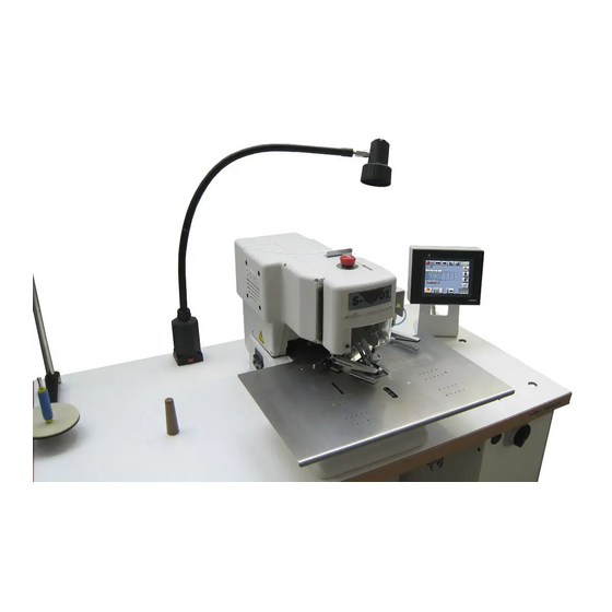
S-4002 ISBH+I A - INTRODUCTION 3. GENERAL MACHINE PARTS DESCRIPTIONS Eye guard Control panel Stand Table top Foot pedal Main Switch Halogen lamp Button Control box Emergency Stop Button Indexer Machine head Released: 10/2020 E-mail: info@amfreece-cars.cz... -
Page 10: Technical Conditions
S-4002 ISBH+I A - INTRODUCTION 4. TECHNICAL CONDITIONS Machine type S-4002 ISBH+I Electronic controller chain-stitch straight buttonhole machine for sewing imitation buttonholes on jacket sleeve. With the automatic indexer, preset programs Description automatically control the sewing of multiple buttonholes either straight or on an angle. -
Page 11: Instructions For Operator Safety And Maintenance
S-4002 ISBH+I A - INTRODUCTION 5. INSTRUCTIONS FOR OPERATOR SAFETY AND MAINTENANCE When installing the machine we recommend the minimum clearances noted above around the machine. Read all of the instructions that follow. DO NOT PUT THE MACHINE INTO OPERATION UNTIL YOU ARE COMPLETELY FAMILIAR WITH ALL INSTALLATION AND OPERATING INSTRUCTIONS. - Page 12 S-4002 ISBH+I A - INTRODUCTION CAUTION: LASER RADIATION DO NOT VIEW DIRECTLY WITH OPTICAL INSTRUMENTS Read carefully the supplemental rules described below before setting up laser system. C.C. E.A. laser product has been designed and manufactured specifically for the work place and for use in working, conditions.
-
Page 13: Special Accessories
S-4002 ISBH+I A - INTRODUCTION 6. SPECIAL ACCESSORIES - machine device, which is not included in the standard equipment of the machine and a customer can order it Needles 750 SC 80/12, 70/10 • the manufacturer recommends to use these needles when sewing the thin materials •... -
Page 14: B - Machine Installation
S-4002 ISBH+I B - MACHINE INSTALLATION 1. CONTENT OF THE SHIPPING BOX 1. The shipment contains one box. 2. There is a carton with accessories, service manual with parts section and thread stand in the box. 3. During unpacking the shipment, follow the labels which are on a cover. -
Page 15: Power And Air Connection
S-4002 ISBH+I B - MACHINE INSTALLATION 3. POWER AND AIR CONNECTION 1. The machine is equipped with a hand valve . If a customer needs to use a quick coupler , he must order connector A variety of connectors can be used separately or in combination to adapt to the available input supply hose. -
Page 16: Thread Stand Installation
S-4002 ISBH+I B - MACHINE INSTALLATION 4. THREAD STAND INSTALLATION 1. P u t t h e t h r e a d s t a n d t o g e t h e r according to the drawing. -
Page 17: C - Correct Usage
S-4002 ISBH+I C - CORRECT USAGE 1. POWER UP / HOME POSITION 1. Turn the main power switch on by turning clockwise to the I position. 2. The machine is ready for operation when the control panel display lights, the Ready message appears on the display. -
Page 18: Needle Installation
S-4002 ISBH+I C - CORRECT USAGE 2. NEEDLE INSTALLATION WARNING! Before performing this adjustment, switch the main machine power off to prevent accidental starting of the machine. Disconnect the air supply and dissipate any stored energy. Use needles ordering number 02.0750.2.110 (750SC 90/14) only - see accessories. -
Page 19: Threading
S-4002 ISBH+I C - CORRECT USAGE 3. THREADING WARNING! Switch the main machine power off to prevent accidental starting of the machine. Disconnect the air supply and dissipate any stored energy. When threading, see the pictures below. Change the thread tension by nut according to the sewing conditions. -
Page 20: D - Machine Controls
S-4002 ISBH+I D - MACHINE CONTROLS 1. BUTTONHOLE SEWING PROCEDURE 1. Bring the machine to the home position according to the section C1. After this setting, the machine will sew with the indexer according to the parameters set in the program. - Page 21 S-4002 ISBH+I D - MACHINE CONTROLS 6. a) Sewing without indexer Machine can be stopped in any place of the cycle by pressing the Emergency Stop button b) Sewing with indexer If it is necessary to interrupt the cycle during the sewing with indexer (example: needle breakage, thread...
-
Page 22: Operator Control Panel Push Buttons And Switches
S-4002 ISBH+I D - MACHINE CONTROLS 2. OPERATOR CONTROL PANEL PUSH BUTTONS AND SWITCHES Buttonhole programs selected in the indexer Step forward / backward in the indexer sequence sequence Daily counter signalization. Press the button to switch Graphic illustration of the adjusted sequence of to the Counter Screen. - Page 23 S-4002 ISBH+I D - MACHINE CONTROLS By pressing the button you switch to the Counter Screen: Total counter of buttonholes sewn on the machine Daily buttonhole counter Daily counter counting direction (ascending or descending) Daily counter reset Released: 02/2022 1-17...
-
Page 24: Buttonhole Parameters Screen
S-4002 ISBH+I D - MACHINE CONTROLS 3. BUTTONHOLE PARAMETERS SCREEN Buttonhole program number selection / indication Buttonhole name Initial slow sewing speed Number of stitches being sewn at initial slow sewing speed Sewing speed Position of the buttonhole (shifts buttonhole closer / further from the sleeve edge) -
Page 25: Indexer Parameters Screen
S-4002 ISBH+I D - MACHINE CONTROLS 4. INDEXER PARAMETERS SCREEN Selection of buttonhole program numbers in the indexer sequence This symbol indicates indexer cycle interruption at the particular buttonhole. Press the buttonhole icon to activate cycle interruption at that buttonhole. This feature is mainly useful for thread color exchange. -
Page 26: Service Menu
S-4002 ISBH+I D - MACHINE CONTROLS 5. SERVICE MENU Switch to Program Copy Screen (refer to Chapter D5.2) Switch to Software Information Screen (refer to Chapter D5.3) Password Entering (refer to Chapter D5.1) Switch to Buttonhole Step-by-Step Sewing Screen (refer to Chapter D5.4) Switch to Machine Parameters Screen (refer to Chapter D5.5) -
Page 27: Password Submitting Screen
S-4002 ISBH+I D - MACHINE CONTROLS 5.1. Password Submitting Screen All the buttonhole parameters are protected by the password of level II. Consequently, the buttonhole parameters can be viewed but cannot be changed. Level II password is requested for the change. -
Page 28: Program Copy Screen
S-4002 ISBH+I D - MACHINE CONTROLS 5.2. Program Copy Screen Copying of a buttonhole program Copying of an indexer cycle program 5.3. Software Information Screen Software version numbers 5.4. Buttonhole Step-by-Step Sewing Screen Activation of buttonhole step-by-step sewing mode Proceed to next stitch... -
Page 29: Machine Parameters Screen
S-4002 ISBH+I D - MACHINE CONTROLS 5.5. Machine Parameters Screen Language selection Mechanical bite adjustment – this value must be set according to the adjusted mechanical bite of the sewing head Buttonhole angle setting mode Foot-pedal control setting – clamps control when pedal pressed to first position Foot-pedal control setting –... -
Page 30: Sensors Test Screen
S-4002 ISBH+I D - MACHINE CONTROLS 5.6. Sensors Test Screen 5.7. Valves Test Screen 5.8. X-Y Motors Adjustment Screen Axis home position sensor Axis current position Axis movement test Axis home position establishment Axis home position electronic correction Axis X row... -
Page 31: Sewing Motor Adjustment Screen
S-4002 ISBH+I D - MACHINE CONTROLS 5.9. Sewing Motor Adjustment Screen Sewing motor movement test Sewing motor home position establishment Sewing motor home position electronic correction Sewing motor home position sensor status Sewing motor continual run Sewing motor enable / disable 5.10. -
Page 32: Automatic Home Position
S-4002 ISBH+I D - MACHINE CONTROLS 5.11. Automatic Home Position This machine is equipped with automatic home position of stepper motor axes. This operation is factory set to 200 buttonholes. Master reset (factory set) Machine cycling (testing, running - in) -
Page 33: E - Standard Machine Adjustment
S-4002 ISBH+I E - STANDARD MACHINE ADJUSTMENT 1. MACHINE HOME POSITION 1. The needle bar is in the upper position. The needle descends to the right side of the throat plate slot during the first stitch. The marks on the handwheel and cover casting are aligned. -
Page 34: Needle Bar
S-4002 ISBH+I E - STANDARD MACHINE ADJUSTMENT 3. NEEDLE BAR 3.1. Needle Bar Crank Position Turn the hand wheel until the mark is at 12 o‘clock. The needle bar need to be in the top position. If the needle bar is... -
Page 35: Bite
S-4002 ISBH+I E - STANDARD MACHINE ADJUSTMENT 4. BITE Before the bite adjustment, remove the pulley cover the head cover 4.1. Bite Cam Adjustment 1. Check if the machine is in the home position. 2. Tilt the machine on the rest wood pin . -
Page 36: Bite Width Adjustment
S-4002 ISBH+I E - STANDARD MACHINE ADJUSTMENT 4.2. Bite Width Adjustment To adjust the bite width, first remove the head cover. The S-4002 is fitted with a regular bite throat plate , that allows a bite range of 1.5 mm (1/16“) to 2.3 mm (3-32“). -
Page 37: Looper Adjustment
S-4002 ISBH+I E - STANDARD MACHINE ADJUSTMENT 5. LOOPER ADJUSTMENT Before making the loopers adjustment, follow the below described points: 1. Turn the hand wheel and observe the position of the connecting link at both ends of the looper link arm travel . - Page 38 S-4002 ISBH+I E - STANDARD MACHINE ADJUSTMENT The first looper adjustment 1. Bring the machine to the home position and loosen the screws of the looper cam adjust the looper cam to the lowest position. 2. Loosen the looper set screw...
- Page 39 S-4002 ISBH+I E - STANDARD MACHINE ADJUSTMENT The second looper adjustment 10. Insert the second looper on the looper shaft. 11. Loosen the looper holder screw and move the holder so that the needle passes the center of the looper recess. There must be clearance 0,4 mm between the needle and the looper recess.
-
Page 40: Thread Draw-Off
S-4002 ISBH+I E - STANDARD MACHINE ADJUSTMENT 6. THREAD DRAW-OFF 6.1. Adjustment of the Draw-Off Lever Position The correct adjustment ensures a long enough thread tail for starting the sewing of the next buttonhole. Remove the covers because this mechanism adjustment is performed in the rear of the head. Air supply is necessary for this adjustment. -
Page 41: Thread Tension
S-4002 ISBH+I E - STANDARD MACHINE ADJUSTMENT 7. THREAD TENSION The thread tension influences the appearance of the buttonhole. A thread tension change may be needed if the thread and fabric change. Check to be certain all parts, which contact the thread, are smooth and polished with no burrs or sharp edges. -
Page 42: The Correct Position Of The Tension Mechanism
S-4002 ISBH+I E - STANDARD MACHINE ADJUSTMENT 7.2. The Correct Position of the Tension Mechanism 1. Remove the tension assembly from the shaft 2. Check if the distance between the stud slot edge and the pin is 3.5 mm If incorrect, it is necessary to adjust the position on the pin. -
Page 43: Thread Trimming
S-4002 ISBH+I E - STANDARD MACHINE ADJUSTMENT 8. THREAD TRIMMING Trimming mechanism ensures the correct thread trimming after sewing the last stitch. The trimming hook moves in the direction of arrow, both thread loop legs A and B are pulled forward. -
Page 44: Machine Head Clamp-Feet Adjustment
S-4002 ISBH+I E - STANDARD MACHINE ADJUSTMENT 9. MACHINE HEAD CLAMP-FEET ADJUSTMENT 9.1. Clamp Height Adjustment Make sure the air-supply is switched on and the clamp-feet are in up position. If the clamp-feet are not in up position, push the button from the machine touch-screen panel. -
Page 45: Clamp-Feet Pressure Adjustment
S-4002 ISBH+I E - STANDARD MACHINE ADJUSTMENT 9.3. Clamp-Feet Pressure Adjustment The whole length of the clamp-feet must hold the garment evenly with same pressure; if this is not the case, it is necessary to readjust the correct pressure of clamp-feet... -
Page 46: Changing The Drive Belt
S-4002 ISBH+I E - STANDARD MACHINE ADJUSTMENT 10. CHANGING THE DRIVE BELT 1. Remove the pulley cover after loosing the M4 screws 2. By turning the handwheel adjust the position of the shaft so that the screw on the pulley... -
Page 47: Stepper - Motors Home Position Adjustment
S-4002 ISBH+I E - STANDARD MACHINE ADJUSTMENT 11. STEPPER - MOTORS HOME POSITION ADJUSTMENT 11.1. Bedplate Y-Axis 1. Remove the cover-plate. 2. Press Y-axis home button – now check that the bedplate front inner edge is in one line with the throat- plate front edge as per the picture –... -
Page 48: Sewing-Motor Home Position Adjustment
S-4002 ISBH+I E - STANDARD MACHINE ADJUSTMENT 11.3. Sewing-Motor Home Position Adjustment 1. Check the distance of the sensor from the machine case edge to be 22 mm – refer to the picture below. For adjustment loosen the screw ; maintain the distance 0.3 – 0.5 mm between the sensor and ring 2. -
Page 49: F - Indexer
S-4002 ISBH+I F - INDEXER 1. INTRODUCTION Indexer is a device capable of automatic sewing of a batch of imitation buttonholes on jacket sleeve with defined number of buttonholes, their spacing and angle. Indexer is composed of the clamping mechanism, Y-axis drive, thread pick-up and covers. -
Page 50: Indexer Function
S-4002 ISBH+I F - INDEXER 3. INDEXER FUNCTION Indexer allows sewing of buttonholes with straight or angle clamp-feet movement. All indexer parameters are adjustable from the touch-screen control panel. Angle Angle can be set common for all buttonholes at once or individually for each buttonhole. -
Page 51: Home Position Adjustment
S-4002 ISBH+I F - INDEXER 4. HOME POSITION ADJUSTMENT 4.1. Indexer Clamp-feet Adjustment – Axis Y 1. Activate the indexer from the touch-screen panel by pressing the button 2. By pressing the buttons move the indexer clamp-feet to the rightmost position (left indexer foot is close to the sewing head clamp-feet), adjust the angle to 0°. -
Page 52: The Indexer Clamping Feed Pressure Adjustment
S-4002 ISBH+I F - INDEXER 5. THE INDEXER CLAMPING FEED PRESSURE ADJUSTMENT 1. First place the material under the left clamping feed. 2. Press the button on display. Pull the clamped material and check if the material is held well. -
Page 53: Thread Pick-Up Adjustment
S-4002 ISBH+I F - INDEXER 6. THREAD PICK-UP ADJUSTMENT If the thread is not caught and held after trimming it is necessary to adjust the thread pick-up. 1. The machine must be in the home position. 2. Disconnect the air tubes of the thread puller. -
Page 54: G - Maintenance
S-4002 ISBH+I G - MAINTENANCE Warning: • Check for damage to electrical cables • Check safety covers for damage and replace if needed immediately • Keep your hands out of the sewing area • Do not modify the machine in any way, which could eliminate safety parts •... - Page 55 S-4002 ISBH+I G - MAINTENANCE 6. Remove the filter cover with cleaning pad . Remove the dust from the cleaning pad or in case of considerable dirt, wash it using a mild detergent. Perform the same cleaning on the rear fan.
-
Page 56: Periodic Maintenance
S-4002 ISBH+I G - MAINTENANCE 2. PERIODIC MAINTENANCE once a day (8 hours of operation) - cleaning of the sewing mechanism area and inner frame of the machine - lubrication of mechanisms - see section G4. once a week (40 hours of operation) -
Page 57: Machine Lubrication
S-4002 ISBH+I G - MAINTENANCE 4. MACHINE LUBRICATION 1. It is necessary to lubricate the places shown below before the machine is switched on for the first time or after a long idle period. Use oil ESSO TERESSO 32 or similar quality. - Page 58 S-4002 ISBH+I G - MAINTENANCE 5. Tilt the machine head on the rest pin and lubricate the places shown in the picture. looper shafts looper cam surfaces bite cam surfaces Tilt the sewing head back into the sewing position. 6. After lubrication it is important to sew minimum 10 buttonholes on scrap fabric to dispel any excess oil. Wipe all visible excess oil from the mechanism in the work area.
-
Page 59: Machine Disposal
S-4002 ISBH+I G - MAINTENANCE 5. MACHINE DISPOSAL 1. To ensure machine ecological disposal, it is necessary to remove nonmetallic parts from the machine. To take these parts out, it is necessary to perform the partial dismantling of the machine, remove covers, dismantle the machine arm and remove the frame. -
Page 60: H - Pneumatic Diagram
S-4002 ISBH+I H - PNEUMATIC DIAGRAM Released: 10/2020 1-54 E-mail: info@amfreece-cars.cz... - Page 61 S-4002 ISBH+I H - PNEUMATIC DIAGRAM Released: 10/2020 1-55 E-mail: info@amfreece-cars.cz...
-
Page 62: I - Electrical Diagram
S-4002 ISBH+I I - ELECTRICAL DIAGRAM Released: 04/2023 1-56 E-mail: info@amfreece-cars.cz... - Page 63 S-4002 ISBH+I TROUBLESHOOTING 1. MECHANICAL FAULTS..........................2. INDEXER FAULTS............................ 3. ELECTRICAL FAULTS..........................4. ERROR MESSAGES OF THE CONTROL PANEL................... 5. ERROR MESSAGES OF THE SERVO....................6. MOTOR INTERFACE..........................2-10 Revised: 10/2020 E-mail: info@amfreece-cars.cz...
- Page 64 S-4002 ISBH+I TROUBLESHOOTING 1. MECHANICAL FAULTS FAULT POSSIBLE CAUSE PROBABLE SOLUTION Needle, looper, throat plate damaged Change damaged parts Thread breakage Incorrect needle sewing Check the adjustment of the mechanism adjustment mechanisms Thread tension is too tight Adjust correct tension Incorrect threading See section C3 for checking.
- Page 65 S-4002 ISBH+I TROUBLESHOOTING FAULT POSSIBLE CAUSE PROBABLE SOLUTION Trimming knife damaged Replace knife Thread Wrong adjustment of pulling hook See section E8 trimmed at the Throttle valve regulating tension disc See section E7 end of the cycle is too loose.
- Page 66 S-4002 ISBH+I TROUBLESHOOTING 2. INDEXER FAULTS FAULT POSSIBLE CAUSE PROBABLE SOLUTION Thread pick Thread puller position adjusted incorrectly See section F6 for adjustment does not catch the Change Thread Pick-up delay parameter Thread Pick-up delay set incorrectly thread breaks in indexer menu...
- Page 67 Sensor BQ10 failure Replace the sensor 12.0008.4.181 To set the servo amplifier - call AMF Reece Check the servo amplifier and servo service, alternatively replace motor (page 2-9) and servo amplifier (page 2-9) When sewing operation...
- Page 68 S-4002 ISBH+I TROUBLESHOOTING FAULT POSSIBLE CAUSE PROBABLE SOLUTION Axis X motor not establishes Axis X motor failure Test motor Axis X - refer to chapter D5.8 home position Sensor BQ1 failure Test sensor BQ1 Axis Y motor not establishes Axis Y motor failure Test motor Axis Y - refer to chapter D5.8...
- Page 69 S-4002 ISBH+I TROUBLESHOOTING 4. ERROR MESSAGES OF THE CONTROL PANEL Error Nr. DESCRIPTION Machine is not in home position. Error 01 Press home button to bring the machine to the home position. Low air pressure. Error 04 Air pressure is bellow 4.0 bar. Check the air supply.
- Page 70 The following messages can be seen on the servo, which is placed inside the control box. In order to eliminate these messages, switch off the machine for 1 minute. Then switch the machine on again. The error message should not appear on the display. If the message appears - call AMF Reece service. PWR - Power supply indication:...
- Page 71 S-4002 ISBH+I TROUBLESHOOTING Alarm Alarm reset Error detection function Detection details and cause of error code possible Power supply The DC voltage of the main circuit fell beloww the specificed value while undervoltage the RUN Command Input was ON Overvoltage The DC voltage of the main circuit is abnormally high Overcurrent flowed to the IGBT.
- Page 72 S-4002 ISBH+I TROUBLESHOOTING 6. MOTOR INTERFACE The following interface is in between the PLC and individual motor drivers: Axis indexer Y Axis indexer X Axis Y Axis X Sewing servo-motor Revised: 10/2020 2-10 E-mail: info@amfreece-cars.cz...
- Page 73 S-4002 ISBH+I TABLE OF CONTENTS NEEDLE BAR ....................3-2 CLAMPING ....................3-4 THREAD TRIMMER ..................3-6 FEED MECHANISM ..................3-8 LOOPER MECHANISM ................3-10 BITE MECHANISM ................... 3-12 BASE ....................3-14 BEDPLATE TOP ..................3-16 BEDPLATE BOTTOM ................3-18 THREAD DRAW-OFF ................3-20 HEAD ....................
-
Page 74: Needle Bar
S-4002 ISBH+I NEEDLE BAR * SILK VERSION Revised: 04/2023 E-mail: info@amfreece-cars.cz... - Page 75 S-4002 ISBH+I NEEDLE BAR PART NUMBER DESCRIPTION QTY. 01.2193.0.000 SCREW-SET 01.6551.0.000 O-RING 01.7447.1.000 GUIDE 01.7804.0.000 BEARING 01.7805.0.000 BEARING 01.7809.0.000 RETAINING RING 02.0750.2.110 NEEDLE 08.6000.5.016 SCREW M5-16 08.6000.6.016 SCREW M6-16 08.6400.3.005 SCREW M3-5 08.6400.4.004 SCREW M4-4 08.6400.5.005 SCREW M5-5 12.0010.4.013 CABEL BINDER 12.1045.2.001...
-
Page 76: Clamping
S-4002 ISBH+I CLAMPING Revised: 04/2023 E-mail: info@amfreece-cars.cz... - Page 77 S-4002 ISBH+I CLAMPING PART NUMBER DESCRIPTION QTY. 01.2376.0.000 SCREW-FLAT HEAD 07.6045.0.046 PIN 4-10 08.6002.3.006 SCREW M3-6 08.6002.3.008 SCREW M3-8 08.6002.4.022 SCREW M4-22 08.6002.6.012 SCREW M6-12 08.6100.5.012 SCREW M5-12 08.6202.5.016 SCREW M5-16 08.6402.3.006 SCREW M3-6 08.6712.3.000 NUT M3 08.6712.6.000 NUT M6 08.6852.5.000...
-
Page 78: Thread Trimmer
S-4002 ISBH+I THREAD TRIMMER Revised: 04/2023 E-mail: info@amfreece-cars.cz... - Page 79 S-4002 ISBH+I THREAD TRIMMER PART NUMBER DESCRIPTION QTY. 08.6002.4.012 SCREW M4-12 08.6102.4.008 SCREW M4-8 08.6312.3.018 SCREW 08.6402.3.004 SCREW M3-4 08.6712.5.000 NUT M5 08.6802.3.000 SPRING WASHER M3 08.6802.4.000 SPRING WASHER M4 08.6852.3.000 WASHER M3 08.6852.4.000 WASHER M4 12.0008.3.416 AIR TUBE- J3B 12.0008.3.804...
-
Page 80: Feed Mechanism
S-4002 ISBH+I FEED MECHANISM Revised: 04/2023 E-mail: info@amfreece-cars.cz... - Page 81 S-4002 ISBH+I FEED MECHANISM PART NUMBER DESCRIPTION QTY. 24.0203.0.000 SME MOTOR “X” AXIS 24.0204.0.000 SME MOTOR “Y” AXIS 07.6045.0.037 PIN 3-16 07.6321.0.001 BEARING PLATE 07.6440.0.033 SPRING 08.6000.5.010 SCREW M5-10 08.6002.3.008 SCREW M3-8 08.6002.4.016 SCREW M4-16 08.6002.5.022 SCREW M5-22 08.6102.3.008 SCREW M3-8 08.6400.6.006...
-
Page 82: Looper Mechanism
S-4002 ISBH+I LOOPER MECHANISM * SILK VERSION Revised: 04/2023 3-10 E-mail: info@amfreece-cars.cz... - Page 83 S-4002 ISBH+I LOOPER MECHANISM PART NUMBER DESCRIPTION QTY. 01.1382.0.000 SCREW 6-40x4 01.1397.0.000 SCREW 6-40x4,8 24.0197.0.000 SCREW 6-40x4 08.6000.3.010 SCREW M3-10 08.6000.4.014 SCREW M4-14 08.6100.5.020 SCREW M5-20 08.6700.8.000 NUT M8 08.6710.5.000 NUT M5 08.6800.4.000 WASHER 4 08.6850.8.000 WASHER 8 12.2010.1.002 BEARING LR 12.3010.0.037...
-
Page 84: Bite Mechanism
S-4002 ISBH+I BITE MECHANISM Revised: 04/2023 3-12 E-mail: info@amfreece-cars.cz... - Page 85 S-4002 ISBH+I BITE MECHANISM PART NUMBER DESCRIPTION QTY. 07.6321.0.025 BEARING 07.6440.0.028 SPRING 08.6000.3.010 SCREW M3-10 08.6000.4.014 SCREW M4-14 08.6000.6.025 SCREW M6-25 08.6100.3.008 SCREW M3-8 08.6200.4.008 SCREW M4-8 08.6400.4.004 SCREW M4-4 08.6700.5.000 NUT M5 08.6850.4.000 WASHER M4 12.0008.4.280 CLAMP CABLE 12.0008.6.800 O-RING 10x2 17.0019.1.062...
-
Page 86: Base
S-4002 ISBH+I BASE Revised: 04/2023 3-14 E-mail: info@amfreece-cars.cz... - Page 87 08.6200.5.020 SCREW M5-20 08.6700.5.000 NUT M5 08.6832.4.000 WASHER M4 12.0008.4.052 LABEL GROUND 12.0008.4.197 CLAMP 12.1016.0.002 NAIL 1.86x6.35 12.8000.1.047 LABEL - AMF REECE 12.8000.1.074 LABEL CE 22.1010.0.000 HINGE 24.0038.1.000 BASE GASKET 24.0111.1.000 BASE SOUND DEADENER 24.0191.0.000 FELT 24.6005.2.000 BASE S-4002 Revised: 04/2023 3-15 E-mail: info@amfreece-cars.cz...
-
Page 88: Bedplate Top
S-4002 ISBH+I BEDPLATE TOP Revised: 04/2023 3-16 E-mail: info@amfreece-cars.cz... - Page 89 S-4002 ISBH+I BEDPLATE TOP PART NUMBER DESCRIPTION QTY. 01.2084.0.000 SCREW 08.6002.6.022 SCREW M6-20 08.6112.3.008 SCREW M3-8 08.6112.3.016 SCREW M3-16 08.6733.3.000 NUT M3 08.6802.6.000 SPRING WASHER M6 08.6852.3.000 WASHER M3 08.6892.6.000 WASHER M6 22.3034.0.000 THROAT PLATE 22.3068.2.000 SCREW 24.3055.7.000 COVER PLATE 24.3099.0.000...
-
Page 90: Bedplate Bottom
S-4002 ISBH+I BEDPLATE BOTTOM Revised: 04/2023 3-18 E-mail: info@amfreece-cars.cz... - Page 91 S-4002 ISBH+I BEDPLATE BOTTOM PART NUMBER DESCRIPTION QTY. 01.7805.0.000 BEARING 08.6000.3.006 SCREW M3-6 08.6000.4.006 SCREW M4-6 08.6000.5.016 SCREW M5-16 08.6000.6.016 SCREW M6-16 08.6002.4.008 SCREW M4-8 08.6002.4.010 SCREW M4-10 08.6002.4.012 SCREW M4-12 08.6100.3.008 SCREW M3-8 08.6100.6.035 SCREW M6-35 08.6400.5.005 SCREW M5-5 08.6400.5.010...
-
Page 92: Thread Draw-Off
S-4002 ISBH+I THREAD DRAW-OFF Revised: 04/2023 3-20 E-mail: info@amfreece-cars.cz... - Page 93 S-4002 ISBH+I THREAD DRAW-OFF PART NUMBER DESCRIPTION QTY. 01.6551.0.000 O-RING 1,78x2.57 01.7447.1.000 GUIDE 07.6045.0.053 PIN 6m6X20 08.6000.3.006 SCREW M3-6 08.6000.4.010 SCREW M4-10 08.6000.4.016 SCREW M4-16 08.6000.5.016 SCREW M5-16 08.6200.4.016 SCREW M4-16 08.6400.4.004 SCREW M4-4 08.6400.5.010 SCREW M5-10 08.6710.6.000 NUT M6 08.6800.4.000...
-
Page 94: Head
S-4002 ISBH+I HEAD * SILK VERSION Revised: 04/2023 3-22 E-mail: info@amfreece-cars.cz... - Page 95 S-4002 ISBH+I HEAD PART NUMBER DESCRIPTION QTY. 01.7806.0.000 BUSHING 07.6045.0.037 PIN 3-16 07.6440.0.051 SPRING 08.6000.4.005 SCREW M4-5 08.6000.4.016 SCREW M4-16 08.6000.6.025 SCREW M6-25 08.6000.8.025 SCREW M8-25 08.6000.8.040 SCREW M8-40 08.6002.5.040 SCREW M5-40 08.6100.5.020 SCREW M5-20 08.6102.3.008 SCREW M3-8 08.6200.5.008 SCREW M5-8 08.6400.5.005...
-
Page 96: Covers
S-4002 ISBH+I COVERS Revised: 04/2023 3-24 E-mail: info@amfreece-cars.cz... - Page 97 S-4002 ISBH+I COVERS PART NUMBER DESCRIPTION QTY. 05.1394.0.000 LABEL 08.6000.3.008 SCREW M3-8 08.6000.3.016 SCREW M3-16 08.6000.3.040 SCREW M3-40 08.6000.4.006 SCREW M4-6 08.6000.4.070 SCREW M4-70 08.6100.4.008 SCREW M4-8 08.6100.5.016 SCREW M5-16 08.6200.4.008 SCREW M4-8 08.6850.5.000 WASHER 5,3 12.1016.0.002 NAIL 12.8000.0.438 LABEL - GUALITY 12.8000.1.061...
-
Page 98: Lubrication
S-4002 ISBH+I LUBRICATION Revised: 04/2023 3-26 E-mail: info@amfreece-cars.cz... - Page 99 S-4002 ISBH+I LUBRICATION PART NUMBER DESCRIPTION QTY. 08.6000.4.006 SCREW M4-6 08.6002.5.008 SCREW M5-8 08.6852.5.000 WASHER 5,3 12.0008.3.023 TY-WRAP 12.0008.4.225 CLAMP 17.0095.1.329 OIL INDICATOR 22.0104.0.000 OIL GAUGE RESERVOIR 22.0108.0.000 WICK HOLDER 22.0120.0.000 HOLDER 22.0229.0.000 STRAIGHT FITTING 24.0139.1.000 LUBRICATING WICK KIT 24.0141.1.000...
-
Page 100: Indexer Clamping Bracket
S-4002 ISBH+I INDEXER CLAMPING BRACKET Revised: 04/2023 3-28 E-mail: info@amfreece-cars.cz... - Page 101 S-4002 ISBH+I INDEXER CLAMPING BRACKET PART NUMBER DESCRIPTION QTY. 08.6100.5.008 SCREW M5-8 08.6733.8.000 NUT M8 12.2050.0.007 NEEDLE BEARING 12.2060.0.006 AXIAL BEARING 12.2099.5.002 AXIAL RING 24.4109.0.000 INDEXER CLAMPING BRACKET Revised: 04/2023 3-29 E-mail: info@amfreece-cars.cz...
-
Page 102: Indexer Clamping 30
S-4002 ISBH+I INDEXER CLAMPING 30° 48 49 Revised: 04/2023 3-30 E-mail: info@amfreece-cars.cz... - Page 103 S-4002 ISBH+I INDEXER CLAMPING 30° PART NUMBER DESCRIPTION QTY. 06.2400.0.653 STEPPERMOTOR SM3 ASSY. 08.6002.3.005 SCREW M3-5 08.6002.3.006 SCREW M3-6 08.6002.3.010 SCREW M3-10 08.6002.4.006 SCREW M4-6 08.6002.5.012 SCREW M5-12 08.6002.5.014 SCREW M5-14 08.6102.5.008 SCREW M5-8 08.6102.5.012 SCREW M5-12 08.6132.3.008 SCREW M3-8 08.6202.4.010...
- Page 104 S-4002 ISBH+I INDEXER CLAMPING 30° 48 49 Revised: 04/2023 3-32 E-mail: info@amfreece-cars.cz...
- Page 105 S-4002 ISBH+I INDEXER CLAMPING 30° PART NUMBER DESCRIPTION QTY. 24.4123.1.000 SENSOR BRACKET 24.4124.0.000 MOTOR HOLDER 24.4126.0.000 COVER GEAR 24.4127.0.000 MOTOR GEAR 10z-20° RIGHT 24.4143.0.000 BRACKET 24.4148.0.000 SENSOR BRACKET Revised: 04/2023 3-33 E-mail: info@amfreece-cars.cz...
-
Page 106: Y - Axis Indexer
S-4002 ISBH+I Y - AXIS INDEXER Revised: 04/2023 3-34 E-mail: info@amfreece-cars.cz... - Page 107 S-4002 ISBH+I Y - AXIS INDEXER PART NUMBER DESCRIPTION QTY. 06.2400.2.958 MOTOR - INDEXER 08.6002.3.005 SCREW M3-5 08.6002.4.008 SCREW M4-8 08.6002.4.012 SCREW M4-12 08.6002.5.010 SCREW M5-10 08.6002.5.012 SCREW M5-12 08.6002.5.016 SCREW M5-16 08.6002.5.018 SCREW M5-18 08.6002.5.020 SCREW M5-20 08.6402.5.005 SCREW M5-5 08.6702.5.000...
-
Page 108: Indexer Cover
S-4002 ISBH+I INDEXER COVER Revised: 04/2023 3-36 E-mail: info@amfreece-cars.cz... - Page 109 S-4002 ISBH+I INDEXER COVER PART NUMBER DESCRIPTION QTY. 08.6002.5.010 SCREW M5-10 08.6002.5.012 SCREW M5-12 08.6002.5.016 SCREW M5-16 08.6002.6.020 SCREW M6-20 08.6102.5.012 SCREW M5-12 08.6712.4.000 NUT M4 08.6712.5.000 NUT M5 08.6802.5.000 SPRING WASHER M5 08.6802.6.000 SPRING WASHER M6 08.6842.5.000 WASHER 5 08.6892.6.000...
-
Page 110: Thread Pick-Up
S-4002 ISBH+I THREAD PICK-UP Revised: 04/2023 3-38 E-mail: info@amfreece-cars.cz... - Page 111 S-4002 ISBH+I THREAD PICK-UP PART NUMBER DESCRIPTION QTY. 08.6102.5.016 SCREW M5-16 08.6702.3.000 NUT M3 12.0008.3.416 AIR TUBE- J11B ‐ 12.0008.3.499 CYLINDER 12.0010.3.027 CONNECTOR 12.0010.3.028 CONNECTOR 12.0010.3.029 SPEED VALVE 12.0010.3.080 AIR TUBE- J11A ‐ 24.4001.0.050 CYLINDER HOLDER ASSEMBLY 24.4002.0.000 PICK-UP 24.4003.0.000 SUPPORT 24.4004.0.000...
-
Page 112: Electrical
S-4002 ISBH+I ELECTRICAL Revised: 04/2023 3-40 E-mail: info@amfreece-cars.cz... - Page 113 S-4002 ISBH+I ELECTRICAL PART NUMBER DESCRIPTION QTY. 12.0010.4.200 MAIN POWER SWITCH (QS1) 12.0010.4.285 INTERFACE OB1 (OB1) 12.0008.4.665 FUSE - T2A (F1,F2) 12.0008.4.664 FUSE - T10A (F3,F4) 12.0008.4.050 BRIDGE GND 12.0010.4.385 BOARD TERMINAL (TB1) 12.0010.4.251 FILTER R7A (Z1) 06.8024.0.605 SERVODRIVE 400W (U10) 12.0010.4.168...
-
Page 114: Panel Kit
S-4002 ISBH+I PANEL KIT Revised: 04/2023 3-42 E-mail: info@amfreece-cars.cz... - Page 115 S-4002 ISBH+I PANEL KIT PART NUMBER DESCRIPTION QTY. 06.2400.0.619 CABLE DISPLAY POWER 06.2400.0.620 CABLE DISPLAY 08.6032.4.010 SCREW M4-10 08.6662.3.006 SCREW 08.6663.5.025 SCREW 4,8-25 12.0010.4.300 DISPLAY 19.0014.7.003 SCREW-PANEL 24.0168.0.000 DISPLAY HOLDER 24.0174.0.000 DISPLAY STAND 68.0358.0.800 PANEL COVER Revised: 04/2023 3-43 E-mail: info@amfreece-cars.cz...
-
Page 116: Table
S-4002 ISBH+I TABLE 30 31 16 20 16 20 16 19 SILK Revised: 04/2023 3-44 E-mail: info@amfreece-cars.cz... - Page 117 S-4002 ISBH+I TABLE PART NUMBER DESCRIPTION QTY. 04.1416.1.003 LABEL 04.9024.0.362 BASE STOP 04.9024.0.363 SUPPORTING CONSOLE 04.9024.0.364 UPPER CONSOLE 04.9024.0.907 TABLE TOP CROSSWISE 04.9024.1.000 FRAME KIT ASSY. 04.9024.1.345 BASE ASSY. 08.6002.4.010 SCREW M4-10 08.6002.5.016 SCREW M5-16 08.6312.8.020 SCREW M8-20 08.6312.8.022 SCREW M8-22 08.6312.8.035...
-
Page 118: Filter Regulator
S-4002 ISBH+I FILTER REGULATOR Revised: 04/2023 3-46 E-mail: info@amfreece-cars.cz... - Page 119 S-4002 ISBH+I FILTER REGULATOR PART NUMBER DESCRIPTION QTY. 06.7300.0.027 PRESSURE GAUGE 08.6202.5.012 SCREW M5x12 08.6702.5.000 NUT M5 08.6802.5.000 SPRING WASHER M5 08.6852.5.000 WASHER 5,3 12.0008.3.415 AIR TUBE ‐ 12.0008.3.463 HAND VALVE 12.0010.3.137 FILTER REGULATOR 12.0010.3.138 REGULATOR BRACKET 12.0010.3.141 CONNECTOR Revised: 04/2023 3-47 E-mail: info@amfreece-cars.cz...
-
Page 120: Valve Block
S-4002 ISBH+I VALVE BLOCK Revised: 04/2023 3-48 E-mail: info@amfreece-cars.cz... - Page 121 S-4002 ISBH+I VALVE BLOCK PART NUMBER DESCRIPTION QTY. 06.2400.0.640 CABLE ASSY. X4 08.6663.4.038 SCREW 4,2-38 12.0008.3.426 PLUG 12.0008.3.790 BLANKING PLATE 12.0010.3.099 SILENCER 12.0010.3.105 5/2 VALVE 12.0010.3.106 CONNECTOR 12.0010.3.107 MANIFOLD PLATE 12.8000.0.446 LABELS - VALVES 1-30 Revised: 04/2023 3-49 E-mail: info@amfreece-cars.cz...
-
Page 122: Valve Block - Silk
S-4002 ISBH+I VALVE BLOCK - SILK Revised: 04/2023 3-50 E-mail: info@amfreece-cars.cz... - Page 123 S-4002 ISBH+I VALVE BLOCK - SILK PART NUMBER DESCRIPTION QTY. 06.2400.0.640 CABLE ASSY. X4 08.6663.4.038 SCREW 4,2-38 12.0008.3.426 PLUG 12.0010.3.099 SILENCER 12.0010.3.105 5/2 VALVE 12.0010.3.106 CONNECTOR 12.0010.3.107 MANIFOLD PLATE 12.8000.0.446 LABELS - VALVES Revised: 04/2023 3-51 E-mail: info@amfreece-cars.cz...
-
Page 124: Accessories
S-4002 ISBH+I ACCESSORIES * SILK VERSION Revised: 04/2023 3-52 E-mail: info@amfreece-cars.cz... - Page 125 S-4002 ISBH+I ACCESSORIES PART NUMBER DESCRIPTION QTY. 02.0750.2.110 NEEDLE 05.1322.0.000 OIL RESERVOIR 08.6000.4.005 SCREW M4-5 08.6850.4.000 WASHER M4 12.0008.6.001 SCREWDRIVER 2,5 -75 12.0008.6.100 ALLEN WRENCH 2 mm 12.0008.6.101 ALLEN WRENCH 3 12.0008.6.102 ALLEN WRENCH 4 12.0008.6.105 ALLEN WRENCH 1,5 mm 12.0008.6.112...
- Page 127 S-4002 ISBH+I INDEX PART NUMBER PAGE DET PART NUMBER PAGE DET PART NUMBER PAGE DET 22979047 3-53 07.6045.0.053 3-21 08.6002.4.010 3-45 27513603 3-25 07.6321.0.001 08.6002.4.012 01.1382.0.000 3-11 07.6321.0.025 3-13 08.6002.4.012 3-19 01.1397.0.000 3-11 07.6440.0.028 3-13 08.6002.4.012 3-35 01.2084.0.000 3-17 07.6440.0.033 08.6002.4.016...
- Page 128 S-4002 ISBH+I INDEX PART NUMBER PAGE DET PART NUMBER PAGE DET PART NUMBER PAGE DET 08.6132.3.008 3-31 08.6702.5.000 3-35 08.6852.4.000 08.6200.4.008 3-13 08.6702.5.000 3-47 08.6852.4.000 08.6200.4.008 3-25 08.6702.8.000 3-45 08.6852.4.000 3-19 08.6200.4.016 3-21 08.6710.5.000 3-11 08.6852.4.000 3-35 08.6200.5.008 3-23 08.6710.6.000 3-21 08.6852.4.000...
- Page 129 S-4002 ISBH+I INDEX PART NUMBER PAGE DET PART NUMBER PAGE DET PART NUMBER PAGE DET 12.0008.4.682 3-41 12.0010.4.013 12.8000.1.047 3-15 12.0008.4.833 3-41 12.0010.4.013 3-21 12.8000.1.061 3-25 12.0008.6.001 3-53 12.0010.4.067 3-41 12.8000.1.074 3-15 12.0008.6.100 3-53 12.0010.4.093 3-31 15.1431.0.100 3-31 12.0008.6.101 3-53 12.0010.4.093...
- Page 130 S-4002 ISBH+I INDEX PART NUMBER PAGE DET PART NUMBER PAGE DET PART NUMBER PAGE DET 22.0064.0.000 3-13 22.3068.2.000 3-17 24.0141.1.000 3-27 22.0091.0.000 3-21 22.3219.0.000 3-19 24.0148.0.000 3-23 22.0100.0.000 3-11 22.6002.0.000 3-23 24.0154.0.000 3-25 22.0100.0.000 3-13 23.2106.0.000 3-11 24.0168.0.000 3-43 22.0104.0.000 3-27 23.2107.0.000...
- Page 131 S-4002 ISBH+I INDEX PART NUMBER PAGE DET PART NUMBER PAGE DET PART NUMBER PAGE DET 24.3099.0.000 3-17 24.6001.4.000 3-25 24.3100.0.000 3-17 24.6003.0.000 3-25 24.3102.0.000 3-25 24.6004.2.001 3-25 24.3103.0.000 3-25 24.6005.2.000 3-15 24.4001.0.050 3-39 24.6100.5.000 3-17 24.4002.0.000 3-39 68.0024.0.990 3-45 24.4003.0.000 3-39 68.0358.0.800...
Need help?
Do you have a question about the S-4002 ISBH+I and is the answer not in the manual?
Questions and answers