
Subscribe to Our Youtube Channel
Related Manuals for AMF S-4000 TKF


Summary of Contents for AMF S-4000 TKF
- Page 1 S-4000 TKF, LS MODEL Omron TACKER AND LABEL SEWER PARTS AND SERVICE MANUAL MACHINE SERIAL No: 97.2441.4.001 PART NUMBER 01 / 2022...
- Page 3 However, the satisfaction and goodwill of our customers are of pri- mary concern to AMF Reece, Inc. In the event that a warranty matter is not handled to your satisfaction, please contact AMF Reece office: AMF Reece - Cars s.r.o.
-
Page 5: Table Of Contents
S-4000 TKF, LS Omron TABLE OF CONTENTS A - INTRODUCTION 1. BASIC INFORMATION ........................1 2. SAFETY DEVICE AND LABEL ......................2 3. GENERAL MA CHINE PAR TS DESCRIPTION................3 4. SPECIFICATIONS..........................4 5. TABLE TYPE ............................5 6. INSTRUCTIONS FOR OPERATOR SAFETY AND MAINTENANCE ..........6 7. - Page 6 S-4000 TKF, LS Omron TABLE OF CONTENTS 14. THREAD DRAW-OFF ........................37 14.1. Adjustment of the Draw-Off Lever Position ....................... 37 14.2. The thread end adjustment ..........................37 14.3. Locking the stitches ............................37 15. THREAD TENSION ........................... 38 15.1. Adjustment of the tension discs opening ......................38 15.2.
-
Page 7: Basic Information
A halogen work light is included with the S-4000 TKF and LS, to enhance operator safety and product quality. Special electronic and mechanical safety devices protect the operator and the machine. There is a special power lock out switch that permits the machine to be locked in the off position, so that it cannot be cycledacci dentally. -
Page 8: Safety Device And Label
S-4000 TKF, LS Omron A - INTRODUCTION 2. SAFETY DEVICE AND LABEL Warning Eye guard Covers removed, possible injury Head cover Grounding Fan cover Rotational direction Manometer with pressure sensor Standard Label Machine head Needle bar cover Table Frame Released: 01/2022... -
Page 9: General Ma Chine Par Ts Description
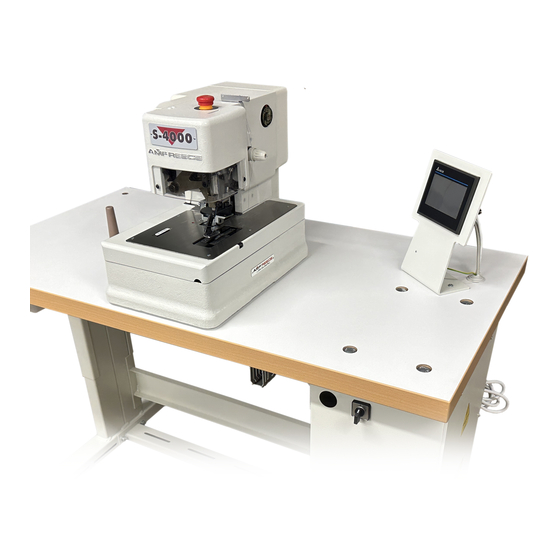
S-4000 TKF, LS Omron A - INTRODUCTION 3. GENERAL MA CHINE PAR TS DESCRIPTION Control box Main switch Hand wheel Foot pedal Emergency Stop Button Clamps Up/Down button Motor Air pressure regulator Table Top Air pressure adjustment knob Thread Stand... -
Page 10: Specifications
S-4000 TKF, LS Omron A - INTRODUCTION 4. SPECIFICATIONS Released: 01/2022 E-mail: info@amfreece-cars.cz... - Page 11 S-4000 TKF, LS Omron A - INTRODUCTION 5. TABLE TYPE Parallel Crosswise Crosswise embedded Universal - possible adjustable: parallel/crosswise Released: 01/2022 E-mail: info@amfreece-cars.cz...
-
Page 12: Instructions For Operator Safety And Maintenance
S-4000 TKF, LS Omron A - INTRODUCTION 6. INSTRUCTIONS FOR OPERATOR SAFETY AND MAINTENANCE When installing the machine we recommend the minimum clearances noted above around the machine. Read all of the instructions that follow. DO NOT PUT THE MACHINE INTO OPERATION UNTIL YOU ARE COMPLETELY FAMILIAR WITH ALL INSTALLATION AND OPERATING INSTRUCTIONS. -
Page 13: Special Accessories
S-4000 TKF, LS Omron A - INTRODUCTION CAUTION! - Perform all regular service as described in this manual. - If there is any problem with the power supply, turn off the main power switch. - Do not remove, paint over, damage or in any way change safety labels. If a safety label cannot be easily read, replace it. - Page 14 * To connect the tube with inner Ø12 and Ø16, it is also necessary to order Ø10 Needle guard and clamp foot 3/8“ a 3/4“ kit (for machine S-4000 TKF only) - to sew in range 6,3 - 9,5 mm, use needle guard 3/8“ and clamp foot 3/8“...
- Page 15 S-4000 TKF, LS Omron A - INTRODUCTION Clamping-bite 1,5 - 2 mm - possible to order, for TKF (order no. 03.5524.0.032) Clamping foot-bite 4 mm - possible to order, for TKF 24.3211.0.000 Clamp foot 1 1/2 24.3212.0.000 Clamp foot 3/4 24.3213.0.000 Clamp foot 3/8...
-
Page 16: Content Of The Shipping Box
A package of accessories is supplied with the machine, please refer to page 3-48 for detailed descriptions. The height of the working area is normaly set in range 830 - 850 mm from the manufacturer (and embedded) S-4000 TKF is in range 780 —... - Page 17 S-4000 TKF, LS Omron B - MACHINE INSTALLATION Remove the shipping strap after unpacking the machine, the use of this strap is recommended anytime the machine is transported. (This is valid for all types of tables - parallel, crosswise, universal).
-
Page 18: Power And Air Connection
S-4000 TKF, LS Omron B - MACHINE INSTALLATION 3. POWER AND AIR CONNECTION 1. The machine is equipped with a quick coupler required with connector for inner Ø of the tube 10. The connector for inner Ø of the tube 8 is not supplied with the machine, a customer has to order it. - Page 19 S-4000 TKF, LS Omron B - MACHINE INSTALLATION Head Pneumatic - thread draw-off, tension release - thread trim - clamp feet J0I1 - air input BQ2 - regulator with air pressure switch air distribution Tubes 0, 1, 2 — X => distribution from a regulator...
-
Page 20: Thread Stand Installation
S-4000 TKF, LS Omron B - MACHINE INSTALLATION 4. THREAD STAND INSTALLATION 1. Put the thread stand together according to the drawing. 2. Position of the locking ring allows assembly of the thread stand for various thickness of the table top. Threaded end of the... -
Page 21: C - Proper Application
S-4000 TKF, LS Omron C - PROPER APPLICATION 1. POWER UP / HOME POSITION 1. Turn the main power switch on by turning clockwise to the I position. 2. The machine is ready for operation when the control panel display lights, the Ready message appears on the display and the green LED lights on display. -
Page 22: Needle Installation
S-4000 TKF, LS Omron C - PROPER APPLICATION 2. NEEDLE INSTALLATION WARNING! Before performing this adjustment, switch the main machine power off to prevent accidental starting of the machine. Disconnect the air supply and dissipate any stored energy. Use needles ordering number 02.0750.2.110 (750SC 90/14) only - see accessories. -
Page 23: Threading
S-4000 TKF, LS Omron C - PROPER APPLICATION 3. THREADING WARNING! Switch the main machine power off to prevent accidental starting of the machine. Disconnect the air supply and dissipate any stored energy. When threading, see the pictures below. Change the thread tension by nut according to the sewing conditions. -
Page 24: D - Machine Controls
S-4000 TKF, LS Omron D - MACHINE CONTROLS 1. PROGRESS OF SEWING 1. Bring the machine to the home position according to the section C1. 2. Be certain that the machine is threaded correctly according to the section C3 and insert the work under the clamp feet. -
Page 25: Operator Control Panel Push Buttons And Switches
S-4000 TKF, LS Omron D - MACHINE CONTROLS 2. OPERATOR CONTROL PANEL PUSH BUTTONS AND SWITCHES Display Daily cycle messages counter Service menu Machine (test entry, counter model reset, program version) Stitcher head clamps The programming menu stitcher head Display messages: •... -
Page 26: The Programing Menu Stitching Head
S-4000 TKF, LS Omron D - MACHINE CONTROLS 3. THE PROGRAMING MENU STITCHING HEAD Enter the sewing head program menu by pressing button Parameters set 1 Parameters set 2 Released: 01/2022 1-20 E-mail: info@amfreece-cars.cz... - Page 27 S-4000 TKF, LS Omron D - MACHINE CONTROLS Setting the machine cycling. (On/Off). Setting the maximum sewing speed. If the button is backlit, the function is active. (Range 1000 - 3840 ppm) Setting the foot pedal position. (Possible setting 1step/2steps).
-
Page 28: Tests
S-4000 TKF, LS Omron D - MACHINE CONTROLS 4. TESTS W a r n i n g !!! The tests can be carried out by qualified service men only. Inputs BQ1 – The end position sensor BQ1. The symbol signalizes correct function of the sensor of the end position of the cam (HOME) BQ1. -
Page 29: Program Version
S-4000 TKF, LS Omron D - MACHINE CONTROLS 5. PROGRAM VERSION 6. COUNTER RESET Daily cycle counter Servis cycle counter (not reset) Daily cycle counter reset Released: 01/2022 1-23 E-mail: info@amfreece-cars.cz... -
Page 30: Parameter Checklist
S-4000 TKF, LS Omron D - MACHINE CONTROLS 7. PARAMETER CHECKLIST PARAMETER RANGE SETTING 1 step 2 steps 2 steps 1 repeat 2 repeat 1 repeat ½ repeat 0 - 3 500 - 1000 rpm 1000 1000 - 3840 rpm... -
Page 31: Ma Chine Home Position
S-4000 TKF, LS Omron E - STANDARD MACHINE ADJUSTMENT 1. MA CHINE HOME POSITION The needle bar is i n the upper position. The needle descends to the right side of the throat plate slot during the first stitch. The marks on the handwheel and cover casing are aligned. -
Page 32: Needle Bar
S-4000 TKF, LS Omron E - STANDARD MACHINE ADJUSTMENT 4. NEEDLE BAR 4.1. Needle bar crank position Turn the handwheel and loosen the screw in the needle bar crank . Turn the handwheel until the needle bar reaches the upper position. Pulley screw on the main shaft should be in the same line with screw . -
Page 33: Bite
S-4000 TKF, LS Omron E - STANDARD MACHINE ADJUSTMENT 5. BITE Before the bite adjustment, remove the pulley cover and the head cover 5.1. Bite cam a) Check if the machine is i n the home position. b) Tilt the machine onto the rest pin... -
Page 34: Bite Width Adjustment
S-4000 TKF, LS Omron E - STANDARD MACHINE ADJUSTMENT 5.2. Bite width adjustment To adjust the bite width, first remove the head cover for access to adjustments. The S-4000 is fitted with a regular bite throat plate , that allows a bite range of 1.5 mm (1/16“) to 2.3 mm (3/31“). -
Page 35: Feeding
S-4000 TKF, LS Omron E - STANDARD MACHINE ADJUSTMENT 6. FEEDING 1. Tilt the sewing head onto the rest pin. 2. Bevel Gear Adjustments Manually turn the handwheel counter clockwise until the drive spring in the main cam engages with a indent . The feeding lever is on the highest point of the feeding cam. -
Page 36: Slip Clutch
S-4000 TKF, LS Omron E - STANDARD MACHINE ADJUSTMENT 7. SLIP CLUTCH The slip clutch pressure is factory set and under normal conditions will not need adjusting. The correct clutch torque setting is 0.43 Nm (60 to 65 inch ounces). -
Page 37: Looper Adjustments
S-4000 TKF, LS Omron E - STANDARD MACHINE ADJUSTMENT 9. LOOPER ADJUSTMENTS Before making this adjustment, follow the points described below: • Turn the handwheel and observe the position of the connecting link at both ends of the looper link arm travel . - Page 38 S-4000 TKF, LS Omron E - STANDARD MACHINE ADJUSTMENT The first looper adjustment 1. Bring the machine to the home position and loosen the screws of the looper cam adjust the looper cam to the lowest position. 2. Loosen the looper set screw...
- Page 39 S-4000 TKF, LS Omron E - STANDARD MACHINE ADJUSTMENT The second looper adjustment 10. Insert the second looper on the looper shaft. 11. Loosen the looper holder screw and move the holder so that the needle passes the center of the looper recess.
-
Page 40: The Clamp Plate Home Position
S-4000 TKF, LS Omron E - STANDARD MACHINE ADJUSTMENT 10. THE CLAMP PLATE HOME POSITION 1. The home position of the clamp plate before sewing is: a) the bevel gears on the feed shaft are not engaged with the vertical bevel gear b) the clamp plate is positioned all the way to the right (to the head casting) 3. -
Page 41: Clamp Plate To The Center Of The Throat Plate Adjustment
S-4000 TKF, LS Omron E - STANDARD MACHINE ADJUSTMENT 11. CLAMP PLATE TO THE CENTER OF THE THROAT PLATE ADJUSTMENT 1. If the clamp plate is not adjusted to the center of the throat plate , tilt the sewing head against the rest pin. -
Page 42: Head Clamp Foot Adjustment
S-4000 TKF, LS Omron E - STANDARD MACHINE ADJUSTMENT 13. HEAD CLAMP FOOT ADJUSTMENT 13.1. Adjustment f or clamp height Be sure that air supply is switch on and the clamp foot is opened. If clamp foot is not opened, push the clamp Up / Down button. -
Page 43: Thread Draw-Off
S-4000 TKF, LS Omron E - STANDARD MACHINE ADJUSTMENT 14. THREAD DRAW-OFF 14.1. Adjustment of the Draw-Off Lever Position The correct adjustment ensures a long enough thread tail for starting the next sewing. Remove the covers because this mechanism adjustment is performed i n the rear of the head. Air supply is necessary for this adjustment. -
Page 44: Thread Tension
S-4000 TKF, LS Omron E - STANDARD MACHINE ADJUSTMENT 15. THREAD TENSION The thread tension influences the appearance of the sewing. A thread tension change may be needed if the thread and fabric change. Check to be certain all parts, which contact the thread, are smooth and polished with no burrs or sharp edges. -
Page 45: The Correct Position Of The Tension Mechanism
S-4000 TKF, LS Omron E - STANDARD MACHINE ADJUSTMENT 15.2. The correct position of the tension mechanism a) remove the tension assembly from the shaft b) check if the distance between the stud slot edge and the pin is 3.5 mm If incorrect, it is necessary to adjust the position on the pin. -
Page 46: Thread Trimming
S-4000 TKF, LS Omron E - STANDARD MACHINE ADJUSTMENT 16. THREAD TRIMMING The trimming mechanism ensures the correct thread trimming after sewing the last stitch. The trimming hook moves in the direction of the arrow, both thread loop legs A and B are pulled forward. When the thread hook approaches the end of the stroke, leg A contact the trimming knife, cutting the thread. -
Page 47: The Hold Down Adjustment
S-4000 TKF, LS Omron E - STANDARD MACHINE ADJUSTMENT 17. THE HOLD DOWN ADJUSTMENT (S-4000 LS modification only) 1. It is necessary to adjust the hold down loosening the screw , if: a) the hold down is not in the centre of the clamp... -
Page 48: Adjustment Of The Stopping Sensor Position
S-4000 TKF, LS Omron E - STANDARD MACHINE ADJUSTMENT 18. ADJUSTMENT OF THE STOPPING SENSOR POSITION Follow the steps described below to set the position of the sensor. 1. Put machine in the service mode (see E2). 2. Turn the handwheel counter clockwise until the stop disk finger is perpendicular to the sensor 3. -
Page 49: Changing The Drive Belt
S-4000 TKF, LS Omron E - STANDARD MACHINE ADJUSTMENT 19. CHANGING THE DRIVE BELT 1. Remove the pulley cover after loosening the M4 screws 2. By turning the handwheel adjust the position of the shaft so that the screw on the pulley... -
Page 50: Voltage Guard
S-4000 TKF, LS Omron E - STANDARD MACHINE ADJUSTMENT 20. VOLTAGE GUARD The voltage guard - relay HRN-35 (VC1) as an extra accessories is placed in the machine control box. It is adjusted and sealed from a manufacturer. If the supply voltage is in the required range, the green LED Un indicates it on the voltage monitoring relay. -
Page 51: Machine Cleaning And Maintenance
S-4000 TKF, LS Omron F - MAINTENANCE Warning: - Check for damage to electrical cables - Check safety covers for damage and replace if needed immediately - Keep your hands out of the sewing area - Do not modify the machine in any way, which could eliminate safety parts - Do not attach external lights or other devices to the machine´s electrical system... - Page 52 S-4000 TKF, LS Omron F - MAINTENANCE 6. Remove the filter cover with cleaning pad Remove the dust from the cleaning pad or in case of considerable dirt, wash it using a mild detergent. Perform the same cleaning on the rear fan.
-
Page 53: Periodic Maintenance
S-4000 TKF, LS Omron F - MAINTENANCE 2. PERIODIC MAINTENANCE once a day (8 hours of operation) - cleaning of the sewing mechanism area and inner frame of the - machine - lubrication of mechanisms - see area F4. once a week (40 hours of operation) -
Page 54: Lubrication Diagram
S-4000 TKF, LS Omron F - MAINTENANCE 3. LUBRICATION DIAGRAM The machine is mainly equipped with needle and ball bearings, which in combination with a single lubrication circuit decrease the requirements for maintenance. Circuit I - with the oil supply in oil indicator for lubrication of the bite, feeding and looper levers and worm gears. In case of replacement of any part of di stribution, it is possible to order the tube kits and wicks. -
Page 55: Machine Lubrication
S-4000 TKF, LS Omron F - MAINTENANCE 4. MACHINE LUBRICATION 1. It is necessary to lubricate the places shown below before the machine is switched on for the first time or after a long idle period. Use oil ESSO TERESSO 32 or similar quality . - Page 56 S-4000 TKF, LS Omron F - MAINTENANCE 5. Tilt the machine head on the rest pin and lubricate the places shown in the picture. Looper shafts Feed cam surfaces Shifter Bite cam surfaces Bevel gears Trimmer shaft Looper cam surfaces 6.
-
Page 57: Machine Disposal
S-4000 TKF, LS Omron F - MAINTENANCE 5. MACHINE DISPOSAL 1. To ensure machine ecological disposal, it is necessary to remove nonmetallic parts from the machine. To take these parts out, it is necessary to perform the partial dismantling of the machine, remove covers, dismantle the machine arm and remove the frame. -
Page 58: G - Pneumatic Diagram
S-4000 TKF, LS Omron G - PNEUMATIC DIAGRAM Released: 01/2022 1-52 E-mail: info@amfreece-cars.cz... -
Page 59: H - Electrical Diagram
S-4000 TKF, LS Omron H - ELECTRICAL DIAGRAM Released: 01/2022 1-53 E-mail: info@amfreece-cars.cz... - Page 60 S-4000 TKF, LS Omron H - ELECTRICAL DIAGRAM Released: 01/2022 1-54 E-mail: info@amfreece-cars.cz...
- Page 61 S-4000 TKF, LS Omron H - ELECTRICAL DIAGRAM Released: 01/2022 1-55 E-mail: info@amfreece-cars.cz...
- Page 62 S-4000 TKF, LS Omron H - ELECTRICAL DIAGRAM Released: 01/2022 1-56 E-mail: info@amfreece-cars.cz...
- Page 63 S-4000 TKF, LS Omron H - ELECTRICAL DIAGRAM Released: 01/2022 1-57 E-mail: info@amfreece-cars.cz...
- Page 65 S-4000 TKF, LS Omron TROUBLESHOOTING TABLE OF CONTENTS 1. MECHANICAL FAULTS ..................... 2-2 2. CONTROL PANEL DISPLAY ERROR MESSAGES ............. 2-5 3. SERVO ERROR MESSAGES ..................2-6 4. ELECTRICAL FAULTS ....................2-7 Revised: 01/2022 E-mail: info@amfreece-cars.cz...
- Page 66 S-4000 TKF, LS Omron TROUBLESHOOTING Revised: 01/2022 E-mail: info@amfreece-cars.cz...
- Page 67 S-4000 TKF, LS Omron TROUBLESHOOTING Revised: 01/2022 E-mail: info@amfreece-cars.cz...
- Page 68 S-4000 TKF, LS Omron TROUBLESHOOTING Revised: 01/2022 E-mail: info@amfreece-cars.cz...
- Page 69 S-4000 TKF, LS Omron TROUBLESHOOTING Revised: 01/2022 E-mail: info@amfreece-cars.cz...
- Page 70 S-4000 TKF, LS Omron TROUBLESHOOTING Revised: 01/2022 E-mail: info@amfreece-cars.cz...
- Page 71 S-4000 TKF, LS Omron TROUBLESHOOTING Revised: 01/2022 E-mail: info@amfreece-cars.cz...
- Page 72 S-4000 TKF, LS Omron TROUBLESHOOTING Revised: 01/2022 E-mail: info@amfreece-cars.cz...
- Page 73 S-4000 TKF, LS Omron TROUBLESHOOTING Revised: 01/2022 E-mail: info@amfreece-cars.cz...
- Page 75 S-4000 TKF, LS Omron TABLE OF CONTENTS NEEDLE BAR ....................3-2 CLAMPING ....................3-4 THREAD TRIMMER ..................3-6 SHIFTER MECHANISM .................3-9 FEED MECHANISM ..................3-10 LOOPER MECHANISM ................3-14 BASE ......................3-16 BITE MECHANISM ..................3-18 THREAD DRAW - OFF MECHANISM ............3-20 MAIN CAM ....................
-
Page 76: Needle Bar
S-4000 TKF, LS Omron NEEDLE BAR Revised: 01/2022 E-mail: info@amfreece-cars.cz... - Page 77 S-4000 TKF, LS Omron NEEDLE BAR PART NUMBER DESCRIPTION QTY. 22.0195.0.000 Needle Bar 01.2193.0.000 4-60 Screw 24.0510.0.000 Needle Bar Holder ● 08.6400.5.005 M5 x 5 Set Screw 01.7447.1.000 Porcelain Guide ●●● 22.0520.0.000 Needle Bar Clamp 01.6551.0.000 Retaining Ring ●●● 22.0230.0.000 Cupped Washer ●●●...
-
Page 78: Clamping
S-4000 TKF, LS Omron CLAMPING Revised: 01/2022 E-mail: info@amfreece-cars.cz... - Page 79 S-4000 TKF, LS Omron CLAMPING PART NUMBER DESCRIPTION QTY. 24.3205.0.002 R.H. Clamp Mat 22.0173.0.000 Clamp Toggle Pivot Pin 24.0036.0.000 Cylinder Mounting Bracket See Page 3-51 Cylinder ●●●● — 08.6000.5.022 Screw M5 x 22 24.0035.0.000 Cylinder Clevis 08.6000.5.012 Screw M5 x 12 08.6400.4.004...
-
Page 80: Thread Trimmer
S-4000 TKF, LS Omron THREAD TRIMMER Revised: 01/2022 E-mail: info@amfreece-cars.cz... - Page 81 S-4000 TKF, LS Omron THREAD TRIMMER PART NUMBER DESCRIPTION QTY. 20.0093.2.004 Trimmer Hook 20.0092.0.004 Trimmer Actuator 01.2386.0.000 3/16-36 x .5 Hex Screw 12.1045.3.001 E-Clip 24.0080.0.000 Trimmer Shaft 24.0003.0.000 Trimmer Pivot 08.6000.4.012 M4 x 12 Screw 24.0004.0.000 Trimmer Clamp Lever 07.6045.0.042 E-Clip 24.0005.0.000...
-
Page 82: Shifter Mechanism
S-4000 TKF, LS Omron SHIFTER MECHANISM Revised: 01/2022 E-mail: info@amfreece-cars.cz... - Page 83 S-4000 TKF, LS Omron SHIFTER MECHANISM PART NUMBER DESCRIPTION QTY. 08.6000.4.010 M4 x 10 Screw 22.2653.0.000 Left Shifter Arm Spring 08.6000.4.016 M4 x 16 Screw 22.2652.0.000 Left Shifter Arm 08.6000.4.005 M4 x 5 Screw 22.2657.0.000 Right Shifter Arm Spring 22.2656.0.000 Right Shifter Arm 22.0405.2.000...
-
Page 84: Feed Mechanism
S-4000 TKF, LS Omron FEED MECHANISM Revised: 01/2022 3-10 E-mail: info@amfreece-cars.cz... - Page 85 S-4000 TKF, LS Omron FEED MECHANISM PART NUMBER DESCRIPTION QTY. 08.6100.3.030 M3 x 30 Screw 22.0114.0.000 Feed Brake Pressure Plate 22.0121.0.000 Slip Clutch Drive Washer 22.0354.0.000 Slip Clutch Feed Gear 24.0126.0.000 Friction Washer ●●● 22.0312.0.000 Slip Clutch Feed Shaft 22.0061.0.000 Clamp Plate Gear Rack Retainer 07.6440.0.033...
- Page 86 S-4000 TKF, LS Omron FEED MECHANISM Revised: 01/2022 3-12 E-mail: info@amfreece-cars.cz...
- Page 87 S-4000 TKF, LS Omron FEED MECHANISM PART NUMBER DESCRIPTION QTY. 22.0021.0.000 Spring Retain Block 22.0353.0.000 Steel Bevel Gear ● 22.0032.0.000 Bearing Shoulder Screw 07.6321.0.025 Bearing 22.0031.0.000 Bearing Spacer 08.6710.5.000 M5 Nut 22.0232.0.000 Washer 22.0110.0.000 M5 Shoulder Nut 22.0022.0.000 Pivot Shaft 08.6850.8.000...
-
Page 88: Looper Mechanism
S-4000 TKF, LS Omron LOOPER MECHANISM Revised: 01/2022 3-14 E-mail: info@amfreece-cars.cz... - Page 89 S-4000 TKF, LS Omron LOOPER MECHANISM PART NUMBER DESCRIPTION QTY. 08.6400.4.004 M4 x 4 Set Screw 22.2442.0.000 Looper Spacer 22.2410.0.000 Looper Shaft Block 08.6100.5.020 M5 x 20 Screw 22.2440.0.000 Looper Shaft 01.1382.0.000 Screw 20.0094.0.000 Trimmer Knife 20.0111.0.000 First Looper 23.2106.0.000 First Looper Holder 20.0112.0.000...
-
Page 90: Base
S-4000 TKF, LS Omron BASE Revised: 01/2022 3-16 E-mail: info@amfreece-cars.cz... - Page 91 S-4000 TKF, LS Omron BASE PART NUMBER DESCRIPTION QTY. 24.0111.0.000 Base Sound Deadener ●●● 08.6100.5.012 M5 x 12 Screw 08.6100.5.012 M5 x 12 Screw 08.6200.5.012 M5 x 12 Screw 22.1010.0.000 Base Hinge 24.0155.0.000 Base Hinge 24.0038.0.000 Base Gasket ●●● 12.8000.0.016 CE””...
-
Page 92: Bite Mechanism
S-4000 TKF, LS Omron BITE MECHANISM Revised: 01/2022 3-18 E-mail: info@amfreece-cars.cz... - Page 93 S-4000 TKF, LS Omron BITE MECHANISM PART NUMBER DESCRIPTION QTY. 08.6000.6.025 M6 x 25 Screw 22.0008.0.000 Bite Lever ● 24.0055.0.000 Bite Shaft 22.0063.0.000 Bite Shaft Retainer 08.6100.3.008 M3 x 8 FH Screw 08.6000.3.010 M3 x 10 Screw 22.0183.0.000 Collar*Dia. 8 08.6000.4.014...
-
Page 94: Thread Draw - Off Mechanism
S-4000 TKF, LS Omron THREAD DRAW - OFF MECHANISM Revised: 01/2022 3-20 E-mail: info@amfreece-cars.cz... - Page 95 S-4000 TKF, LS Omron THREAD DRAW - OFF MECHANISM PART NUMBER DESCRIPTION QTY. 08.6710.6.000 M6 Nut ●●● 24.0037.0.000 Cylinder Clevis ●●● 08.6000.5.016 M5 x 16 Screw 07.6045.0.042 E-Clip 24.0011.0.000 Knife Drive Lever 24.0014.0.000 Pivot 08.6000.4.010 M4 x 10 Screw 24.0010.0.000 Clamp Collar 24.0009.0.000...
-
Page 96: Main Cam
S-4000 TKF, LS Omron MAIN CAM Revised: 01/2022 3-22 E-mail: info@amfreece-cars.cz... - Page 97 S-4000 TKF, LS Omron MAIN CAM PART NUMBER DESCRIPTION QTY. 22.2607.0.000 Drive Disk/Worm Gear Hub 22.2627.0.000 Shoulder Nut 22.2626.0.000 Drive Disk Switch Spring 07.6440.0.037 Spring 24.3200.0.000 Stop Disk 24.3201.0.000 Feed Reversing Cam 24.3203.0.000 Barring Cam 08.6100.5.010 M5 x 10 Screw 22.0137.0.000...
-
Page 98: Head Assembly
S-4000 TKF, LS Omron HEAD ASSEMBLY Revised: 01/2022 3-24 E-mail: info@amfreece-cars.cz... - Page 99 S-4000 TKF, LS Omron HEAD ASSEMBLY PART NUMBER DESCRIPTION QTY. See Page 3-4 Servomotor ● ●● ●●● 08.6850.5.000 M5 Washer 02** 08.6850.5.000 M5 Washer 08.6000.5.016 M5 x 16 Screw 24.6000.5.000 Head 08.6200.5.008 M5 x 8 Screw 22.0054.0.000 Upper Thread Guide 08.6000.8.025...
- Page 100 S-4000 TKF, LS Omron HEAD ASSEMBLY Revised: 01/2022 3-26 E-mail: info@amfreece-cars.cz...
- Page 101 S-4000 TKF, LS Omron HEAD ASSEMBLY PART NUMBER DESCRIPTION QTY. 39** 22.3255.0.000 Hold Down 40** 01.2527.0.000 3/16-36 Hex Bolt 41** 08.6000.3.010 Screw M3x10 42** 08.6852.3.000 Washer M3 43** 01.6038.0.000 Anchor Pin 44** 20.0681.0.000 Bracket 45** 01.3005.0.000 Nut 3/16-36 46** 22.3252.0.000...
-
Page 102: Bedplate
S-4000 TKF, LS Omron BEDPLATE Revised: 01/2022 3-28 E-mail: info@amfreece-cars.cz... - Page 103 S-4000 TKF, LS Omron BEDPLATE PART NUMBER DESCRIPTION QTY. 08.6120.3.008 M3x8 Screw 22.6101.2.000 Cover Plate s=2mm (standard) Cover Plate s=1mm (Extra Parts) — AMF Reece Label - small 22.0096.0.000 Buttonhole Size Sticker 08.6100.4.006 M4x6 Screw 22.0408.0.000 Trimmer Cover Plate 24.6100.0.000 Bedplate 07.6045.0.054...
-
Page 104: Covers
S-4000 TKF, LS Omron COVERS Revised: 01/2022 3-30 E-mail: info@amfreece-cars.cz... - Page 105 S-4000 TKF, LS Omron COVERS PART NUMBER DESCRIPTION QTY. 08.6100.5.016 Screw M5 x 16 24.0068.0.000 ●●● 24.0067.0.000 Fan Rack 08.6850.5.000 Washer M5 See Page 3-39 Fan Assembly ●● ●●● — 24.6004.1.001 Pulley Cover ● 08.6000.4.070 Screw M4 x 70 08.6000.3.040 Screw M3 x 40 08.6000.3.016...
-
Page 106: Lubrication
S-4000 TKF, LS Omron LUBRICATION Revised: 01/2022 3-32 E-mail: info@amfreece-cars.cz... - Page 107 S-4000 TKF, LS Omron LUBRICATION PART NUMBER DESCRIPTION QTY. 24.0141.0.000 Tubing ●●● 24.0139.0.000 Lubricating Wick ●●● 22.0229.0.000 Straight Fitting 08.6000.4.006 M4 x 6 Screw 22.0120.0.000 Holder 22.0104.0.000 Oil Gauge Reservoir 17.0095.1.329 Wheel ●●● 22.0108.0.000 Wick Holder 17.0027.1.799 Spring 17.0082.6.000 Clamp 08.6000.3.006...
- Page 108 S-4000 TKF, LS Omron TABLE CROSSWISE Revised: 01/2022 3-34 E-mail: info@amfreece-cars.cz...
- Page 109 S-4000 TKF, LS Omron TABLE CROSSWISE PART NUMBER DESCRIPTION QTY. 24.0142.0.050 Table Crosswise Assembly 08.6700.8.000 M8 Nut 17.0019.0.441 Washer 17.0095.1.272 Washer ●●● 12.0008.6.900 Machine Rest Table Pin 12.0008.6.801 Rubber Spring ●●● 12.1016.1.000 Nail ●●● 04.1416.0.003 Label “No. xxxx” 24.0142.0.000 Table Crosswise ●●●...
- Page 110 S-4000 TKF, LS Omron TABLE PARALLEL Revised: 01/2022 3-36 E-mail: info@amfreece-cars.cz...
- Page 111 S-4000 TKF, LS Omron TABLE PARALLEL PART NUMBER DESCRIPTION QTY. 24.0149.0.050 Table Crosswise Assembly 08.6700.8.000 M8 Nut 17.0019.0.441 Washer 17.0095.1.272 Washer ●●● 12.0008.6.900 Machine Rest Table Pin 12.0008.6.801 Rubber Spring ●●● 12.1016.1.000 Nail ●●● 04.1416.0.003 Label “No. xxxx” 24.0149.0.000 Table Crosswise ●●●...
- Page 112 S-4000 TKF, LS Omron TABLE EMBEDDED — TKF Revised: 01/2022 3-38 E-mail: info@amfreece-cars.cz...
- Page 113 S-4000 TKF, LS Omron TABLE EMBEDDED — TKF PART NUMBER DESCRIPTION QTY. 04.9024.0.001 Frame Assembly 08.6700.8.000 Nut M8 17.0019.0.441 Washer 17.0095.1.272 Rubber Washer ●●● 12.0008.6.801 Rubber Spring 12.0008.4.777 Plug 24.0069.9.040 Latch For Kit ●●● 08.6676.3.020 Screw 3,5 x 20 (17) 04.9024.0.900...
- Page 114 S-4000 TKF, LS Omron TABLE UNIVERSAL Revised: 01/2022 3-40 E-mail: info@amfreece-cars.cz...
- Page 115 S-4000 TKF, LS Omron TABLE UNIVERSAL PART NUMBER DESCRIPTION QTY. 24.0150.0.050 Table Assembly 08.6000.8.030 Screw M8x30 17.0019.0.441 Washer 17.0095.1.272 Washer ●●● 12.0008.6.900 Machine Rest Table Pin 24.0081.0.000 Bearing Disk ●●● 24.0082.0.000 Retaining Nut 12.1016.1.000 Nail ●●● 04.1416.0.003 Label “No. xxxx”...
-
Page 116: Electrical - I
S-4000 TKF, LS Omron ELECTRICAL — I Revised: 01/2022 3-42 E-mail: info@amfreece-cars.cz... - Page 117 S-4000 TKF, LS Omron ELECTRICAL — I PART NUMBER DESCRIPTION QTY. 08.6702.4.000 Nut M4 12.0008.4.570 Plug 12.0008.4.563 Emergency Stop Button 12.8000.0.047 Label 08.6102.3.008 Screw 24.0148.0.000 Emergency Stop Cover 24.0069.9.023 Emergency Stop Cable 24.0069.9.004 Cable 12.0008.4.710 Screw Kit 25** 12.0008.4.679 Bulb 12V/12W...
- Page 118 S-4000 TKF, LS Omron ELECTRICAL — I Revised: 01/2022 3-44 E-mail: info@amfreece-cars.cz...
- Page 119 S-4000 TKF, LS Omron ELECTRICAL — I PART NUMBER DESCRIPTION QTY. See Page 3-32 Screw M8x55 — See Page 3-32 Washer — See Page 3-32 — 12.0008.4.155 Label 00.2751.3.602 Label “CAUTION” See Page 3-51 Pressure Gauge — See Page 3-47 Cable —...
-
Page 120: Electrical - I Table Embedded
S-4000 TKF, LS Omron ELECTRICAL — I TABLE EMBEDDED Revised: 01/2022 3-46 E-mail: info@amfreece-cars.cz... - Page 121 S-4000 TKF, LS Omron ELECTRICAL — I TABLE EMBEDDED PART NUMBER DESCRIPTION QTY. 08.6702.4.000 Nut M4 12.0008.4.570 Plug 12.0008.4.563 Emergency Stop Button 12.8000.0.047 Label 08.6102.3.008 Screw 24.0148.0.000 Emergency Stop Cover 24.0069.9.023 Emergency Stop Cable 12.0008.4.777 Plug 12.0008.4.215 Plug 24.0069.9.004 Cable 12.0008.4.710...
- Page 122 S-4000 TKF, LS Omron ELECTRICAL — I TABLE EMBEDDED Revised: 01/2022 3-48 E-mail: info@amfreece-cars.cz...
- Page 123 S-4000 TKF, LS Omron ELECTRICAL — I TABLE EMBEDDED PART NUMBER DESCRIPTION QTY. 12.0008.4.155 Label 00.2751.3.602 Label “CAUTION” See Page 3-51 Pressure Gauge — See Page 3-47 Cable — 12.0010.4.094 Plug — Extra Parts Revised: 01/2022 3-49 E-mail: info@amfreece-cars.cz...
-
Page 124: Electrical - Ii
S-4000 TKF, LS Omron ELECTRICAL — II Revised: 01/2022 3-50 E-mail: info@amfreece-cars.cz... - Page 125 S-4000 TKF, LS Omron ELECTRICAL — II PART NUMBER DESCRIPTION QTY. 24.0069.9.009 Pedal Assembly 24.0069.9.038 Pedal Assembly 06.8800.0.001 Pedal 12.0008.4.296 Bushing 24.0069.9.003 Cable 12.0008.4.306 Cable (1)* 08.6312.8.020 Screw M8x20 08.6852.8.000 Washer M8 24.0097.0.000 Holder Pedal 08.6100.4.012 Screw M4x12 08.6802.8.000 Spring Washer M8 08.6702.8.000...
- Page 126 S-4000 TKF, LS Omron ELECTRICAL — III Revised: 01/2022 3-52 E-mail: info@amfreece-cars.cz...
- Page 127 S-4000 TKF, LS Omron ELECTRICAL — III PART NUMBER DESCRIPTION QTY. Terminal X1 Terminal XO Terminal X12 24.8001.2.005 Servo (U1) 12.0010.4,071 Extension Block (FXON) 24.8001.2.001 12.0010.4.067 Port RS 232 12.0008.4.050 GND Bridge 12.0010.4.078 Filter (Z2) 12.0008.4.665 Fuse T2A 12.0008.4.664 Fuse T10A 12.0008.4.833...
-
Page 128: Panel Kit
S-4000 TKF, LS Omron PANEL KIT Revised: 01/2022 3-54 E-mail: info@amfreece-cars.cz... - Page 129 S-4000 TKF, LS Omron PANEL KIT PART NUMBER DESCRIPTION QTY. 24.0198.0.000 PANEL HOLDER-DELTA 24.8001.2.023 DISPLAY 07.6600.0.004 CLAMP CABLE 08.6832.4.000 WASHER M4 08.6032.4.008 SCREW M4-8 08.6663.5.025 SCREW 4,8-25 06.2400.0.023 CABLE DISPLAY DELTA 06.2400.0.019 CABLE DISPLAY DELTA POWER 12.0008.4.366 RUBBER PLUG 29...
-
Page 130: Pneumatics
S-4000 TKF, LS Omron PNEUMATICS Revised: 01/2022 3-56 E-mail: info@amfreece-cars.cz... - Page 131 S-4000 TKF, LS Omron PNEUMATICS PART NUMBER DESCRIPTION QTY. 08.6000.5.012 Screw M5x12 08.6832.5.000 Washer M5 12.0008.3.659 Regulator Holder 12.0008.3.753 Regulator 08.6850.5.000 Washer M5 08.6700.5.000 Nut M5 12.0008.3.420 Connector 12.0008.3.484 Silencer 12.0008.3.829 Air Supply Block Assembly 12.8000.0.016 Label Kit 12.0008.4.058 Clip ●●●...
-
Page 132: Accessories - Extra Parts
S-4000 TKF, LS Omron ACCESSORIES — EXTRA PARTS Revised: 01/2022 3-58 E-mail: info@amfreece-cars.cz... - Page 133 S-4000 TKF, LS Omron ACCESSORIES — EXTRA PARTS PART NUMBER DESCRIPTION QTY. 20.0093.2.004 Trimmer Hook 20.0094.0.000 Trimmer Knife 22.0209.0.000 Looper Gauge 24.0030.0.000 Main Shaft Pulley Bracket 24.0024.0.000 Needle Bar Shaft Pulley Bracket 02.0750.2.110 Needles, Size 90 05.1322.0.000 Oiler ●●● 12.0008.6.001 Screwdriver 22.0213.0.000...
-
Page 134: Accessories - Clamping
S-4000 TKF, LS Omron ACCESSORIES — CLAMPING Revised: 01/2022 3-60 E-mail: info@amfreece-cars.cz... - Page 135 S-4000 TKF, LS Omron ACCESSORIES — CLAMPING PART NUMBER DESCRIPTION QTY. 03.5524.0.032 Clamping Bite 1,5-2 mm 08.6000.6.025 Screw M6-25 24.3218.0.000 Clamp Arm 24.3219.0.000 Distance 22.3251.0.000 Bracekt Assembly 24.3217.0.000 Clamp Foot-Narow Bite 24.3215.0.000 Clamping Mat - Narow Bite 08.6800.4.000 Washer 4,1 08.6200.4.006...
- Page 136 S-4000 TKF, LS Omron TABLE - ROLLER KIT - EXTRA PARTS Revised: 01/2022 3-62 E-mail: info@amfreece-cars.cz...
- Page 137 S-4000 TKF, LS Omron TABLE - ROLLER KIT - EXTRA PARTS PART NUMBER DESCRIPTION QTY. 08.6312.8.060 SCREW M8-60 08.6702.8.000 NUT M8 08.6802.8.000 SPRING WASHER M8 08.6852.8.000 WASHER M8 12.0008.6.527 ROLLER 12.0008.6.528 ROLLER WITH BRAKE 24.0170.0.000 PLATE 24.0171.0.000 PLATE Revised: 01/2022 3-63 E-mail: info@amfreece-cars.cz...
- Page 139 S-4000 TKF, LS Omron INDEX PART NUMBER PAGE DET PART NUMBER PAGE DET PART NUMBER PAGE DET 00.2751.3.602 3-45 04.9024.0.361 3-39 08.6000.4.005 00.2751.3.602 3-49 04.9024.0.500 3-47 08.6000.4.005 3-13 01.1125.0.000 04.9024.0.650 3-47 08.6000.4.005 3-25 20** 01.1382.0.000 3-15 04.9024.0.900 3-39 08.6000.4.005 3-59 01.1397.0.000 3-15...
- Page 140 S-4000 TKF, LS Omron INDEX PART NUMBER PAGE DET PART NUMBER PAGE DET PART NUMBER PAGE DET 08.6032.4.010 3-47 08.6400.4.004 3-15 08.6700.8.000 3-39 08.6100.3.008 3-19 08.6400.4.004 3-19 08.6702.4.000 3-43 08.6100.3.008 3-29 08.6400.4.004 3-21 08.6702.4.000 3-47 08.6100.3.016 3-25 08.6400.4.005 08.6702.8.000 3-35 08.6100.3.030...
- Page 141 S-4000 TKF, LS Omron INDEX PART NUMBER PAGE DET PART NUMBER PAGE DET PART NUMBER PAGE DET 08.6850.5.000 3-25 12.0008.3.606 3-57 12.0008.4.665 3-53 08.6850.5.000 3-25 02** 12.0008.3.607 3-59 40* — 12.0008.4.679 3-43 25** 1)** 08.6850.5.000 3-29 12.0008.3.608 3-59 12.0008.4.679 3-47 25* 08.6850.5.000 3-31...
- Page 142 S-4000 TKF, LS Omron INDEX PART NUMBER PAGE DET PART NUMBER PAGE DET PART NUMBER PAGE DET 12.0010.4.078 3-53 17.0095.1.272 3-41 22.0063.0.000 3-19 12.0010.4.094 3-49 17.0095.1.329 3-33 22.0064.0.000 3-15 12.1010.2.003 3-25 20.0092.0.004 22.0064.0.000 3-19 12.1011.0.001 3-25 20.0093.2.004 22.0069.0.000 3-19 12.1016.0.000 3-39 ((2)) 20.0093.2.004...
- Page 143 S-4000 TKF, LS Omron INDEX PART NUMBER PAGE DET PART NUMBER PAGE DET PART NUMBER PAGE DET 22.0228.0.000 3-11 22.2631.0.000 3-23 24.0035.0.000 22.0229.0.000 3-33 22.2633.0.000 3-23 24.0036.0.000 22.0230.0.000 22.2651.0.000 24.0037.0.000 3-21 22.0232.0.000 3-13 22.2652.0.000 24.0038.0.000 3-17 22.0232.0.000 3-15 22.2653.0.000 24.0039.1.000 3-21 22.0233.0.000 3-15...
- Page 144 S-4000 TKF, LS Omron INDEX PART NUMBER PAGE DET PART NUMBER PAGE DET PART NUMBER PAGE DET 24.0082.0.000 3-41 24.3203.0.000 3-23 24.0084.0.000 3-41 24.3205.0.001 24.0086.0.000 3-41 24.3205.0.002 24.0087.0.000 3-41 24.3206.0.000 3-59 31* — 24.0089.0.000 3-41 24.3207.0.000 30** 24.0097.0.000 3-51 24.3208.0.000 3-59 48** 24.0100.0.000...
Need help?
Do you have a question about the S-4000 TKF and is the answer not in the manual?
Questions and answers