Table of Contents
Advertisement
Quick Links
Advertisement
Table of Contents

Subscribe to Our Youtube Channel
Related Manuals for u-blox EVK-G31


Summary of Contents for u-blox EVK-G31
- Page 1 EVK-G31, EVK-G35 SARA-G310, SARA-G350 GSM/GPRS Cellular evaluation kit User Guide Abstract This guide explains how to set up the EVK-G31 and EVK-G35 Evaluation Kits to begin evaluating the u-blox SARA-G310 and SARA-G350 GSM/GPRS cellular modules. www.u-blox.com UBX-13001792 - R06...
- Page 2 The information contained herein is provided “as is” and u-blox assumes no liability for the use of the information. No warranty, either express or implied, is given, including but not limited, with respect to the accuracy, correctness, reliability and fitness for a particular purpose of the information.
-
Page 3: Table Of Contents
EVK-G31, EVK-G35 - User Guide Contents Contents ..........................3 Starting up ........................4 EVK-G3x overview ..........................4 EVK-G3x block diagram ........................5 Switches, jumpers and buttons ......................5 LEDs ..............................6 Connectors ............................6 EVK-G35 pinout ........................... 7 EVK-G31 pinout ........................... 9 Software installation ........................... -
Page 4: Starting Up
1 Starting up 1.1 EVK-G3x overview The EVK-G31 and EVK-G35 are powerful and easy-to-use tools that simplify the evaluation of u-blox SARA-G310 and SARA-G350 GSM/GPRS cellular modules. The evaluation kits differ depending on which SARA-G3 series module version is mounted: ... -
Page 5: Evk-G3X Block Diagram
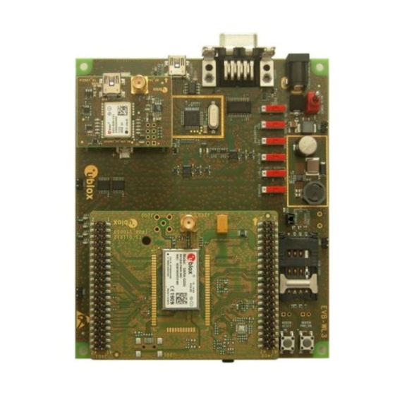
The GNSS adapter board, called ADP-GNSS, contains the u-blox GNSS module, the LDO supply regulator, the GNSS antenna connector, and the USB connector for the GNSS module The boards are connected by means of male header board-to-board connectors mounted on the bottom side of the adapter boards and their corresponding female connectors mounted on the top side of the EVB-WL3 board. -
Page 6: Leds
EVK-G31, EVK-G35 - User Guide 1.4 LEDs Function Description LED # Board Color Main Power Power supply plugged in the 9 - 18 V Power Input DL401 Cellular module supplied. Main Power Switch must be switched on Cellular VCC supply... -
Page 7: Evk-G35 Pinout
EVK-G31, EVK-G35 - User Guide 1.6 EVK-G35 pinout DIL B2B connector SARA-G350 SARA-G350 SARA-G350 SARA-G350 DIL B2B connector Name/Pin Number Signal Name Pin N° Pin N° Signal Name Name/Pin Number J401 Pins 7-8-9-10 J401 Pins 7-8-9-10 J401 Pin 3 V_BCKP... - Page 8 EVK-G31, EVK-G35 - User Guide DIL B2B J401 DIL B2B J400 Signal Name Pin N° Pin N° Signal Name Signal Name Pin N° Pin N° Signal Name Not connected Not connected Not connected V_BCKP Not connected Not connected Not connected...
-
Page 9: Evk-G31 Pinout
EVK-G31, EVK-G35 - User Guide 1.7 EVK-G31 pinout DIL B2B connector SARA-G310 SARA-G310 SARA-G310 SARA-G310 DIL B2B connector Name/Pin Number Signal Name Pin N° Pin N° Signal Name Name/Pin Number J401 Pins 7-8-9-10 J401 Pins 7-8-9-10 J401 Pin 3 V_BCKP... -
Page 10: Software Installation
Table 7: Pin-out of the 42-pin Dual-In-Line Board-to-Board connectors (J401, J400) available on the adapter board ADP-G310 of the EVK-G31 evaluation kit for SARA-G310 modules The pins / interfaces that are not supported by a specific SARA-G3 module product version should be not driven by an external device (see the SARA-G3 series Data Sheet [3] and SARA-G3 and SARA-U2 series System Integration Manual [4] for the features supported by each SARA-G3 module product version). - Page 11 Stop bits: 1 Flow control: HW See Appendix A for how to configure the u-blox m-center AT terminal for Windows. Connect the headset provided with the evaluation kit box to the Headset jack connector (J303 on EVB), if the audio functionality is required.
-
Page 12: Enabling Error Result Codes
EVK-G31, EVK-G35 - User Guide 1.10 Enabling error result codes Command sent by DTE (user) DCE response (module) Description AT+CMEE=2 Enables the cellular module to report verbose error result codes. 1.11 PIN code insertion (when required) Command sent by DTE (user) -
Page 13: Appendix
AT commands Manual [1]. Figure 4: AT Terminal window For more information on using the u-blox m-center cellular module evaluation tool, press the F1 key on your keyboard to open the m-center help window on your computer. UBX-13001792 - R06... -
Page 14: B Setting Up Cellular Packet Data Connection On Pc
EVK-G31, EVK-G35 - User Guide B Setting up cellular packet data connection on PC This section describes how to set up a packet data connection with Windows 7 operating systems (for PC) and EVK-G3x, using the TCP/IP stack of the PC (external TCP/IP stack). - Page 15 EVK-G31, EVK-G35 - User Guide 5. Select: Control panel -> Phones and Modem -> Modems -> Standard Modem 33600 bps Modem -> Properties. 6. Select Change Settings -> Advanced. 7. Add APN settings command (APN shown is just an example. Make sure to have the correct APN defined by the network operator).
-
Page 16: Configuring A New Connection
GPRS account information for the network operator a name for the new connection (e.g. “u-blox GPRS Connection“) 4. The packet data connection is now ready to be used with the EVK-G3x. To check the connection, start a browser. -
Page 17: C Examples Of At Commands
AT commands Manual [1]. For detailed examples of AT commands for network registration and configuration, context activation, data connection management, SIM management and other module settings, see the u-blox AT Commands Examples Application Note [2]. -
Page 18: Sms Management
EVK-G31, EVK-G35 - User Guide Command sent by DTE (user) DCE response (module) Description ATD+3930012345678 Outgoing data call (+3930012345678 is written here as example). CONNECT 9600 Connect to remote ISDN modem. ~ }#À!}!Œ} }4}”}&} }*} } }%}&ú„Ej}’}”}(}”KÌ~~ }#À!}! } }4}”}&} }*} } }%}&ú„Ej}’}”}(}”}”_~~... -
Page 19: Enable Communication Between Cellular And Gnss Modules
Several NMEA messages via Cellular USB or RS232 (UART) can be read. The example below shows how to read a GLL message to get the last available Geographic position Latitude / Longitude. For the full list of NMEA messages that can be read, see the u-blox AT commands manual [1]. Command sent by DTE (user) -
Page 20: D Current Consumption Measurement
EVK-G31, EVK-G35 - User Guide D Current consumption measurement Current consumption of SARA-G3 series modules can be measured on the EVK-G3x by removing the jumper socket from the Cellular VCC supply jumper (J404 on the EVB), described in Figure 5. -
Page 21: Declaration Of Conformities
Any changes or modification made to this equipment will void its compliance to the safety requirements. Maintenance, inspections and/or reparations of the EVK-G3x shall be performed by u-blox AG. Hereby, u-blox AG declares that this EVK-G3x is in compliance with the essential requirements and other relevant provisions of Directive 1999/5/EC. -
Page 22: Contact
EVK-G31, EVK-G35 - User Guide Contact For complete contact information visit us at www.u-blox.com u-blox Offices North, Central and South America Headquarters Asia, Australia, Pacific Europe, Middle East, Africa u-blox America, Inc. u-blox Singapore Pte. Ltd. u-blox AG Phone: +1 703 483 3180... - Page 23 Mouser Electronics Authorized Distributor Click to View Pricing, Inventory, Delivery & Lifecycle Information: u-blox ADP-G310 EVK-G35...
Need help?
Do you have a question about the EVK-G31 and is the answer not in the manual?
Questions and answers