Table of Contents
Advertisement
Quick Links
EVK-NINA-W1/EVK-NINA-B2
Evaluation Kit for NINA-W1 and NINA-B2 modules
User Guide
Abstract
This document describes how to set up the EVK-NINA-W1/EVK-NINA-B2 evaluation kits to evaluate
NINA-W1 series and NINA-B2 series stand-alone modules. It also describes the different options for
debugging and the development capabilities included in the evaluation board.
www.u-blox.com
UBX-17011007 - R05
Advertisement
Table of Contents

Subscribe to Our Youtube Channel
Related Manuals for u-blox EVK-NINA-W1 Series


Summary of Contents for u-blox EVK-NINA-W1 Series
- Page 1 This document describes how to set up the EVK-NINA-W1/EVK-NINA-B2 evaluation kits to evaluate NINA-W1 series and NINA-B2 series stand-alone modules. It also describes the different options for debugging and the development capabilities included in the evaluation board. www.u-blox.com UBX-17011007 - R05...
-
Page 2: Document Information
The information contained herein is provided “as is” and u-blox assumes no liability for its use. No warranty, either express or implied, is given, including but not limited to, with respect to the accuracy, correctness, reliability and fitness for a particular purpose of the information. -
Page 3: Table Of Contents
1.8 Configuration options ..........................12 1.8.1 Power supply ............................12 Setting up the evaluation board ..................... 13 2.1 EVK without software (open CPU) ......................13 2.2 EVK with u-blox connectivity software ....................14 2.2.1 Starting up ............................14 2.2.2 Getting the latest software ......................14 Appendix ................................ 15 Layouts.............................. -
Page 4: Product Description
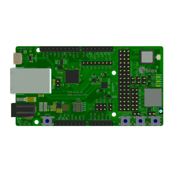
EVK-NINA-W1/EVK-NINA-B2 - User Guide Product description Overview The EVK-NINA-W1/EVK-NINA-B2 evaluation kit includes an evaluation board, which can be used as a reference design for the NINA-W1 or NINA-B2 series modules, a quick start guide, and a USB cable. For the NINA-B221 and the NINA-W1x1 module, the evaluation board is prepared with a U.FL coaxial connector for connecting the external antenna. - Page 5 EVK-NINA-W1/EVK-NINA-B2 - User Guide Figure 1: EVK-NINA-W1/EVK-NINA-B2 evaluation board with U.FL connector for external antenna Figure 2: EVK-NINA-W1/EVK-NINA-B2 evaluation board with internal antenna ⚠ Take care while handling the EVK-NINA-B222 and EVK-NINA-W1x2. Applying force to the NINA module might damage the internal antenna. UBX-17011007 - R05 Product description Page 5 of 21...
-
Page 6: Kit Includes
EVK-NINA-W1/EVK-NINA-B2 - User Guide 1.2 Kit includes 1.2.1 EVK-NINA-B221 and EVK-NINA-W1x1 The EVK-NINA-B221 and EVK-NINA-W1x1 evaluation kits include the following: • EVK-NINA-B221 or EVK-NINA-W1x1 evaluation board • 2.4 GHz foldable antenna (Ex-It 2400) with reverse polarity SMA connector • RP-SMA - U.FL cable assembly, 100 mm length •... -
Page 7: Jumper Description
EVK-NINA-W1/EVK-NINA-B2 - User Guide ☞ When reset-n is released, the module pin 27 is read as boot-n. When IO-0 is connected to the module, it must be held high during start up. 1.4 Jumper description Parameter Description Name Default Enable SW1 Jumper at J5-1_J5-2 connects switch 1 to module pin-7 ... - Page 8 EVK-NINA-W1/EVK-NINA-B2 - User Guide Middle row jumper pin Connected to J14-13 Module pin-17 J14-15 Module pin-18 J16-1 Module pin-8 J16-3 Module pin-27 J16-5 Module pin-25 J16-7 Module pin-24 J16-9 Module pin-31 J16-11 Module pin-35 J16-13 Module pin-32 J16-15 Module pin-36 Table 2: Available module pins at the middle row of jumpers J14 and J16 Connected to Left row...
-
Page 9: Default Jumper Configuration
EVK-NINA-W1/EVK-NINA-B2 - User Guide 1.4.1 Default jumper configuration Mod pin-21 to J18-3 Mod pin-20 to IO22 (RTS) Mod pin-16 to IO25 (DTR) Mod pin-28 to IO5 Mod pin-17 to IO26 (DSR) Mod pin-29 to IO18 3.3V to Mod pin-9 Mod pin-18 to IO27 3.3V to Mod pin-10 Mod pin-27 to IO0 J18-4 to IO19 (CTS) -
Page 10: Leds
EVK-NINA-W1/EVK-NINA-B2 - User Guide 1.5 LEDs Figure 7: Position of LEDs on EVK-NINA-W1/EVK-NINA-B2 Function Description Name Color Power LED Supplied from the EVK 3.3 V DC/DC converter Green UART TxD Flashing LED indicates UART Tx activity (output from the module) DS2 Green UART RxD Flashing LED indicates UART Rx acitivty (input to the module) -
Page 11: Connectors
EVK-NINA-W1/EVK-NINA-B2 - User Guide 1.6 Connectors The available connectors on the EVK-NINA-W1/EVK-NINA-B2 board are shown in Figure 9. Figure 9: EVK-NINA-W1/EVK-NINA-B2 connectors Connector Description J1, J2, J3, J4 Connectors for accessing the NINA-W1 IO signals (GPIO) USB connector; type Micro-B Reserved RF-port at U.FL coaxial connector for external antenna (not used on EVK-NINA-B221 or EVK-NINA-W1x2) RJ45 connector, RMII to PHY... -
Page 12: Configuration Options
EVK-NINA-W1/EVK-NINA-B2 - User Guide 1.8 Configuration options Module pin IO- signal Primary Accessible at Module pin Primary Accessible at number function Jumper/Connector number signal function Jumper/Connector ( 1 ) GPIO-23 J14-5, [J4-5, J7-1] GPIO-22 UART_RTS J14-9, [J3-7] ( 1 ) ( 2 ) GPI-34 J2-3 GPIO-19... -
Page 13: Setting Up The Evaluation Board
• EVK-NINA-W101 • EVK-NINA-W102 When using the NINA-W10 open CPU variant, it is not possible to download the u-blox connectivity software. Use the software developed and compiled using the Espressif SDK on this variant. Information on how to build and FLASH the module when using Espressif SDK is available at the following URL - http://esp-idf.readthedocs.io/en/latest/get-started/index.html. -
Page 14: Evk With U-Blox Connectivity Software
Use the default baud rate 115200, 8N1 with flow control. Now, it is possible to communicate with the module through AT commands. For a list of available AT commands, see the u-blox Short Range AT Commands Manual [5]. 2.2.2 Getting the latest software Go to the u-blox support web page to obtain the latest available software. -
Page 15: Appendix
EVK-NINA-W1/EVK-NINA-B2 - User Guide Appendix A Layouts Figure 10: Primary and secondary side layouts of EVK-NINA-W1/EVK-NINA-B2 UBX-17011007 - R05 Appendix Page 15 of 21... -
Page 16: B Schematic Drawings
V C C = 3 V 3 ; G N D = G N D V C C = 3 V 3 ; G N D = G N D wurth_150141m173100 DRAWING TITLE : U-BLOX AG H E A D E R S / L E D / S W THALWIL SWITZERLAND... - Page 17 P O P U L A T E P O S I T I O N M 1 W I T H N I N A - W 1 3 2 DRAWING TITLE : U-BLOX AG N I N A - W 1...
- Page 18 S H E E T - 4 , R E M O V E D " D N I " O N C 4 2 A N D C 4 3 ( N E E D E D T O R E D U C E C O N D U C T E D E M I S S I O N S ) DRAWING TITLE : U-BLOX AG R E V I S I O N...
-
Page 19: C Glossary
EVK-NINA-W1/EVK-NINA-B2 - User Guide C Glossary Name Definition Communication Clear To Send Data Set Ready Data Terminal Ready Evaluation Kit Ground General Purpose Input GPIO General Purpose Input/Output Input-Output Light-Emitting Diode Physical layer U.FL Miniature coaxial RF connector Universal Serial Bus Radio frequency RMII Reduced Media-Independent Interface... -
Page 20: Related Documents
FTDI FT4232H QUAD HIGH SPEED USB TO MULTIPURPOSE UART/MPSSE IC Datasheet - http://www.ftdichip.com/Support/Documents/DataSheets/ICs/DS_FT4232H.pdf NINA-W1 System Integration Manual, document number UBX-17005730 NINA-B2 System Integration Manual, document number UBX-18011096 ☞ For regular updates to u-blox documentation and to receive product change notifications, register on our homepage (www.u-blox.com). Revision history Revision Date... -
Page 21: Contact
EVK-NINA-W1/EVK-NINA-B2 - User Guide Contact For complete contact information, visit us at www.u-blox.com. u-blox Offices North, Central and South America Headquarters Asia, Australia, Pacific Europe, Middle East, Africa u-blox America, Inc. u-blox Singapore Pte. Ltd. u-blox AG Phone: +1 703 483 3180...
Need help?
Do you have a question about the EVK-NINA-W1 Series and is the answer not in the manual?
Questions and answers