Table of Contents
Advertisement
Quick Links
EVK-ANNA-B112
Evaluation Kit for ANNA-B112 Bluetooth 5 low energy
modules
User Guide
Abstract
This document describes how to set up the EVK-ANNA-B112 evaluation kit to evaluate ANNA-B112
series standalone Bluetooth
debugging and the development capabilities included in the evaluation board.
www.u-blox.com
UBX-18018539 - R01
®
5 low energy modules. It also describes the different options for
Advertisement
Table of Contents

Related Manuals for u-blox EVK-ANNA-B112


Summary of Contents for u-blox EVK-ANNA-B112
- Page 1 Evaluation Kit for ANNA-B112 Bluetooth 5 low energy modules User Guide Abstract This document describes how to set up the EVK-ANNA-B112 evaluation kit to evaluate ANNA-B112 ® series standalone Bluetooth 5 low energy modules. It also describes the different options for debugging and the development capabilities included in the evaluation board.
-
Page 2: Document Information
The information contained herein is provided “as is” and u-blox assumes no liability for its use. No warranty, either express or implied, is given, including but not limited to, with respect to the accuracy, correctness, reliability and fitness for a particular purpose of the information. -
Page 3: Table Of Contents
Product description ..........................4 Overview ................................ 4 1.2 Kit includes ..............................5 1.3 Key features ..............................5 1.4 EVK-ANNA-B112 block diagram ....................... 6 1.5 Connectors ..............................7 1.6 Powering options ............................7 1.6.1 Selecting the power configuration jumpers .................. 8 1.6.2... -
Page 4: Product Description
The u-blox EVK-ANNA-B112 evaluation kit is a versatile development platform that allows quick prototyping of a variety of extremely low-power Internet of Things (IoT) applications, using Bluetooth 5, Bluetooth mesh and NFC. The u-blox EVK-ANNA-B112 boards are available in the following two variants depending on the required antenna: •... -
Page 5: Kit Includes
• Quick Start card 1.3 Key features • u-blox ANNA-B112 Bluetooth low energy module based on the Nordic nRF52832 chipset: Bluetooth 5 support Bluetooth mesh NFC tag functionality Integrated Arm® Cortex®-M4F microcontroller with 512 kB flash, 64 kB RAM, and 64 MHz system clock Wide 1.7-3.6 V supply range... -
Page 6: Evk-Anna-B112 Block Diagram
The block diagram of EVK-ANNA-B112 is shown in Figure 4. Figure 4: EVK-ANNA-B112 block diagram The block diagram shows the major interfaces and internal connections of the EVK-ANNA-B112. The following sections describe in detail how the different interfaces are connected and used, and how the evaluation board may be configured to suit the needs of the user. -
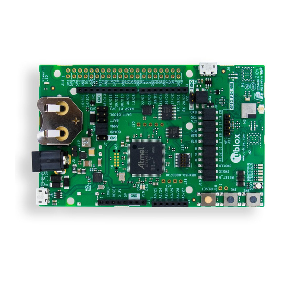
Page 7: Connectors
EVK-ANNA-B112 - User Guide 1.5 Connectors Figure 5 shows the available connectors on the EVK-ANNA-B112 and their layout. Table 1 describes the connectors and their uses in detail. Figure 5: Available connectors and their pinout Connector Function Description annotation Power supply 2.1 mm power jack, the center pin is the positive terminal. -
Page 8: Selecting The Power Configuration Jumpers
Figure 6: Block diagram of the power net distribution 1.6.1 Selecting the power configuration jumpers The EVK-ANNA-B112 offers flexible powering options for the ANNA-B112 module and the board itself. To configure this, jumpers are added to or removed from pin headers, shorting two of the pins together and connecting or disconnecting different power nets on the evaluation board. -
Page 9: Default Power, 3.3 V
EVK-ANNA-B112 - User Guide Connector Schematic Description annotation number net name Regulated 3.3 V net. This net is supplied by the board and will always be powered as long as a power source is connected. 3V3_PI Connects to the Raspberry Pi header’s (J14) 3V3 pins. If a Raspberry Pi is connected, this net must be floating to prevent back currents. -
Page 10: Battery Powered, 3 V
EVK-ANNA-B112 - User Guide Add jumper Connector Description to pins annotation 7, 8 Selects the board regulated 3.3 V net as source for the VDD_ANNA net. 9, 10 Powers up the Interface MCU, USB hub, and UART to USB converter with 3.3 V. -
Page 11: External Supply
EVK-ANNA-B112 - User Guide Add jumper Connector Description to pins annotation 3, 4 Selects the diode protected battery as a source for the VDD_ANNA net. 9, 10 (Optional) Powers up the Interface MCU, USB hub, and UART to USB converter with 3.3 V. -
Page 12: Arduino Interface
Table 7: Jumper configuration when connected to a Raspberry Pi HAT Arduino interface The EVK-ANNA-B112 includes a set of pin headers and mounting holes that are compatible with certain Arduino or Arduino inspired shields. Figure 13 shows the layout of the Arduino interface and Table 8 explains the pinout in more detail. -
Page 13: Arduino Shield Compatibility
Table 8: Pinout of the Arduino UNO R3 compatible interface 1.7.1 Arduino shield compatibility The EVK-ANNA-B112 has an I/O voltage range of 1.7-3.6 V. It can therefore be used only with shields that also support an I/O voltage within this range. -
Page 14: Raspberry Pi Compatible Interface
MCU. 1.8 Raspberry Pi compatible interface The EVK-ANNA-B112 includes a 40-pin IO header that can be used to interface with either a Raspberry Pi computer board or with a Raspberry Pi expansion board (HAT). The EVK-ANNA-B112 uses different hardware and software configurations depending on if it is connected to a Pi or a HAT;... - Page 15 EVK-ANNA-B112 - User Guide Figure 14 shows the layout of the Raspberry Pi interface and Table 10 explains the pinout in detail. There are three mounting holes that can be used for increased mechanical stability. The two on either side of connector J14 are common to all Raspberry Pi boards, but the third one is only compatible with the Pi Zero boards.
-
Page 16: Powering Considerations
ANNA TX and RX pins between IO14 and IO15. If an ANNA-B112 is used, this switch can also be made in the software. By default, the EVK-ANNA-B112 will be configured to simulate a HAT, and IO14 is connected to the ANNA UART_RXD pin and IO15 is connected to the ANNA UART_TXD pin respectively. -
Page 17: Buttons And Leds
Connected to the ANNA RED (IO_29), GREEN (IO_30) and BLUE (IO_31) pins via jumper header J19 Table 12: EVK-ANNA-B112 LED indicators 1.10 Disconnecting ANNA signals from board peripherals All evaluation board peripherals, such as level shifters, LEDs, and the interface MCU will be connected to the ANNA-B112 module by default. - Page 18 EVK-ANNA-B112 - User Guide Figure 16: Jumper headers J19 and J9 that are used to isolate specific ANNA signals Connector Pin number Schematic net Description annotation name RESET_N Reset signal, active low RESET_N_I Connects to the Interface MCU’s reset line...
-
Page 19: Software Debug Options
UART to USB RXD signal Table 13: Pinout of jumper headers - J19 and J9 1.11 Software debug options You can debug the software using the following two options in EVK-ANNA-B112: • Onboard debug solution available on the USB connector •... -
Page 20: Setting Up The Evaluation Board
3. You will now be able to communicate with the module through AT commands. For a list of available AT commands, see the u-blox Short Range AT Commands Manual [3]. To get started with a basic use case setup of the EVK-ANNA-B112 with u-blox connectivity software, see the ANNA-B112 Getting Started [5]. -
Page 21: Appendix
EVK-ANNA-B112 - User Guide Appendix A Placement and Schematics Top view Bottom view UBX-18018539 - R01 Setting up the evaluation board Page 21 of 29... - Page 22 IO_27 IO_27 IO_24 ublox_anna_b1 IO_24 IO_23 IO_23 IO_26 IO_26 IO_25 IO_25 GND_7 DRAWING TITLE : UART_RXD UART_RXD GND_8 U-BLOX AG UART_TXD UART_TXD GND_49 UART_CTS UART_CTS GND_51 THALWIL ANNA MODULE UART_RTS UART_RTS GND_52 SWITZERLAND PROJECT : VERSION : DESIGN BY :...
- Page 23 THIS PAGE IS INTENTIONALLY LEFT BLANK DUE TO LICENSE AGREEMENTS DRAWING TITLE : U-BLOX AG THALWIL INTERFACE MCU SWITZERLAND PROJECT : VERSION : DESIGN BY : mwej EVB-ANNA-B1 PCB_VER.: DATE : Fri May 25 11:22:49 2018 GROUP : u-blox AG...
- Page 24 CBUS1 CBUS1 CBUS2 CBUS2 DHSD_N 100N CBUS3 CBUS3 39R 5% DFSD_P DFSD_N DRAWING TITLE : U-BLOX AG THALWIL HUB, FTDI AND FLASH SWITZERLAND PROJECT : VERSION : DESIGN BY : mwej EVB-ANNA-B1 PCB_VER.: DATE : Thu Feb 15 14:33:41 2018...
- Page 25 RTS_LED UART_TXD_I TXD_LED BLUE UART_DTR_I DTR_LED UART_DSR_I DSR_LED VCC=VDD_IO;GND=GND VCC=VDD_IO;GND=GND VCC=VDD_IO;GND=GND DRAWING TITLE : U-BLOX AG THALWIL HEADERS & BUTTONS SWITZERLAND PROJECT : VERSION : DESIGN BY : mwej EVB-ANNA-B1 PCB_VER.: DATE : Thu Feb 15 14:40:35 2018 GROUP :...
- Page 26 N.C. SGND=GNDA SUSB_MICRO_B_4THGND TP38 100N GNDA 'ZERO VOLT DIODE' - PROTECTS FROM BACK CURRENT ON VBUS LINES VBUS_MCU P_CHANNEL_MOSFET DMG2305UX DRAWING TITLE : U-BLOX AG BASE_1 BASE_1 THALWIL POWER SUPPLY SWITZERLAND PROJECT : VERSION : DESIGN BY : mwej EVB-ANNA-B1 PCB_VER.:...
-
Page 27: B Glossary
EVK-ANNA-B112 - User Guide B Glossary Name Definition Application Programming Interface Clear To Send Data Set Ready Data Terminal Ready Evaluation Board Evaluation Kit Ground General-Purpose Input/Output Light-Emitting Diode Micro Controller Unit Mass Storage Device Near Field Communication U.FL Coaxial RF connector... -
Page 28: Related Documents
[3] u-blox Short Range AT Commands Manual, document number UBX-14044127 [4] SEGGER J-Link software - https://www.segger.com/jlink-software.html [5] ANNA-B112 Getting Started, document number UBX-18020387 ☞ For regular updates to u-blox documentation and to receive product change notifications, register on our homepage (www.u-blox.com). Revision history Revision Date... -
Page 29: Contact
EVK-ANNA-B112 - User Guide Contact For complete contact information, visit us at www.u-blox.com. u-blox Offices North, Central and South America Headquarters Asia, Australia, Pacific Europe, Middle East, Africa u-blox America, Inc. u-blox Singapore Pte. Ltd. u-blox AG Phone: +1 703 483 3180...
Need help?
Do you have a question about the EVK-ANNA-B112 and is the answer not in the manual?
Questions and answers