Table of Contents
Advertisement
Advertisement
Chapters
Table of Contents

Related Manuals for Autool BT250


Summary of Contents for Autool BT250
- Page 1 AUTOOL BT250/BT260 Electrical System Tester User Manual 用户手册 www.autooltech.com...
- Page 2 执行标准 / Execution standard: GB/T8218-1987...
- Page 3 COPYRIGHT INFORMATION Copyright ● All rights reserved by AUTOOL TECH. CO., LTD. No part of this publication may be reproduced, stored in a retrieval system, or transmitted in any form or by any means, electronic, mechanical, photocopying, recording or otherwise, without the prior written permission of AUTOOL.
-
Page 4: Table Of Contents
TABLE OF CONTENTS Cautions ......................1 Using The Test Tool.................... 2 BT250 Tool description..................2 BT260 Tool description..................3 Specifications ....................4 General description ..................4 Power ......................4 Quick Self-Test ....................5 Circuit breaker ....................6 Work mode ...................... 6 Test Applications .................... -
Page 5: Cautions
CAUTIONS Warning Before using the instrument, please read this manual carefully for proper operation. Always perform automotive testing in a safe environment. Wear safety eye protection that meets ANSI standards. Keep clothing, hair, hands, tools, test equipment, etc. away from all moving or hot engine parts. Operate the vehicle in a well ventilated work area: Exhaust gases are poisonous. -
Page 6: Using The Test Tool
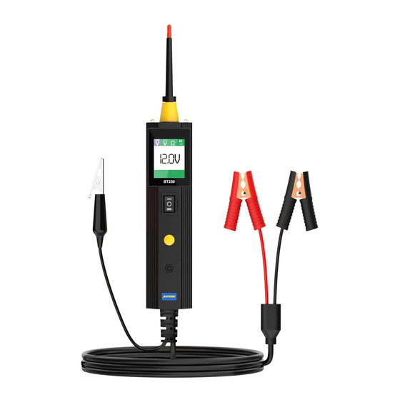
USING THE TEST TOOL BT250 Tool description Contacts the circuit or component Probe Tip to be tested. Illuminates dark work areas or work Head Lights areas at night. LCD Display Indicates test results. Clamps Auxiliary Ground Assists test as a ground lead. -
Page 7: Bt260 Tool Description
BT260 Tool description Contacts the circuit or component Probe Tip to be tested. Illuminates dark work areas or work Head Lights areas at night. LCD Display Indicates test results. Allows you to conduct a positive or negative battery current to the tip for Power Switch activating and testing the function of electrical components. -
Page 8: Specifications
Specifica- Display TFT color display (160x128dpi) tions Operating Temperature 0~60°C (32~140°F) Storage Temperature -40~70°C (-40~185°F) 12.0 or 24.0V power provided External Power via vehicle battery Length 126mm (4.96”) 46.5mm (1.83”) Width Height 35mm (1.38”) 0.105kg (0.23lb) 0.726kg(1.6lb) General The tool is the best electrical tester for reducing diagnostic time in description all 6 to 30 volt vehicle electrical systems. -
Page 9: Quick Self-Test
● Before you test a circuit or component, be sure your tool is in Quick good order by doing a quick self-test. Self-Test ● With the tool connected, perform a quick self-test. The power switch is a momentary rocker switch located on the tool’s body. -
Page 10: Circuit Breaker
IMPORTANT: When powering-up components, you can increase the life of power switch in the tool if you first press the switch, then contact the tip to the component. The arcing will take place at the tip instead of the contacts of the switch. Circuit This product has automatic short circuit protection, its internal breaker... - Page 11 AC voltage ● While the tool in this mode, contact the probe tip to a circuit, then the LCD display will read the Max. voltage, the Min. voltage, frequency and duty cycle. Resistance ● While the tool in this mode, contact the probe tip to a circuit, then the LCD display will read the resistance between the tip and auxiliary ground lead.
- Page 12 Tone On / Off While the tool in this mode, just do a quick press of the mode ● button to toggle the tone on or off. While quickly pressing (a quick press and release) the mode button, if a short high beep is heard, this means the audio tone is turned on.
-
Page 13: Test Applications
TEST APPLICATIONS ● Voltage & While the tool is in DC Voltage mode, contact the probe tip to Polarity a POSITIVE circuit. The red LED will light and the LCD testing displays the voltage with a resolution of 0.1V. If the beep is turned on, a high pitched tone will sound. - Page 14 ● In other cases, the LCD only indicates the resistance value. ● If the resistance value is greater than 200kΩ , the LCD will show “0L”. There is also another way to prove continuity of connections to ground or battery. Power up the connection using the power switch.
-
Page 15: Signal Circuit Testing
Signal Once you extract a DTC from the vehicle and realize that trouble- circuit shooting begins with some kind of sensor circuit, there is a quick testing test you can perform to verify the code. Testing your sensor is easy while using the tool. For example, you suspect there is a problem with your M.A.P. -
Page 16: Test Trailer And Connection Status
to your component. With the power switch rocked forward, power will flow from the positive lead on the battery into the probe tip, through the tip into the component’s positive terminal, into the component and out of the component, through the auxiliary ground lead and back into the tool, and back to the vehicle battery’s ground. -
Page 17: Activating Components In The Vehicle
connector and trailer lights.If the circuit breaker trips, please wait for 15 seconds for it to cool down and then it will automati- cally reset, then press the reset button until it snaps into place. Activating While the tool in DC Voltage mode, contact the probe tip to the components positive terminal of the component, the green LED should light, in the vehicle... -
Page 18: Activating Components With Ground
NOTE: When powering up components, you can increase the life of power switch if you first press the switch, then contact the tip to the component. The arcing will take place at the tip instead of the contacts of the switch. While the tool in DC Voltage mode, contact the probe tip to the Activating negative terminal of the component, the red LED should light. -
Page 19: Checking For Bad Ground Contacts
With this function, if you are contacting a protected circuit, a vehicle’s fuse can be blown or tripped if you apply ground to it. Probe the suspected ground wire or contact with the probe tip. Checking for bad ground ● Observe the green LED. -
Page 20: Red / Green Polarity Led
shorted circuit. Take note of this wire’s identification code or color. Follow the wire as far as you can along the wiring harness. ● Here is an example for this application. If you are following a short in the brake light circuit, you may ●... -
Page 21: Test Tool Specifications
TEST TOOL SPECIFICATIONS DC voltage range 0~65V +1 AC voltage range 0~65V +1 Resistance range 0~200KΩ Frequency response of tone pass through 0Hz~10Khz Circuit breaker rating current 1~10Amp Testing Standard 100% current no trip 150% current trip in one hour 200% current trip in 3~30 seconds trip in 0.5~4.0 seconds... -
Page 22: Test Tool Know-How
TEST TOOL KNOW-HOW Is the Power Scan Probe Tester computer and air bag safe? ● The tool LED and LCD pull no more than 1 milliamp of current, therefore when using it as a test light or multimeter it is comput- er and airbag safe. - Page 23 ② Make sure to install the switch straight and press until flush with casing. It is recommended when buying you get two. This will fix your tool now and give you a spare so you won’t experience any down time in the future.
-
Page 24: Maintenance Service
MAINTENANCE SERVICE Our products are made of long-lasting and durable materials, and we insist on perfect production process. Each product leaves the factory after 35 procedures and 12 times of testing and inspection work, which ensures that each product has excellent quality and performance. -
Page 25: Warranty
Disclaimer All information, illustrations, and specifications contained in this manual, AUTOOL resumes the right of modify this manual and the machine itself with no prior notice. The physical appearance and color may differ from what is shown in the manual, please refer to the actual product. -
Page 26: Return & Exchange Service
RETURN & EXCHANGE SERVICE Return & If you are an AUTOOL user and are not satisfied with the ● Exchange AUTOOL products purchased from the online authorized shopping platform and offline authorized dealers, you can return the products within seven days from the date of receipt;... - Page 27 ......................26 警告......................... 26 产品简介 ......................27 概述 ......................... 27 产品规格......................27 特征 ......................... 27 产品结构 ......................28 BT250 结构图....................28 BT260 结构图....................29 产品使用 ......................30 电源 ......................... 30 快速自检......................30 自动断路器 ...................... 31 工作模式......................31 测试应用 ......................34 电压与正负极测试...
- Page 28 规格参数 ......................42 常见问题 ......................43 维修保养服务 ..................... 45 维修保养 ......................45 保修服务 ......................46 保修方式......................46 声明 ......................... 46 退换货服务 ......................47 退换货 ......................47...
-
Page 29: 版权信息 版权
版权信息 版权 版权所有! 未征得深圳市偶然科技有限公司的书面同意, 任何公 ● 司或个人不得以任何形式 (电子、 机械、 影印、 录制或其他形式) 对本说明书进行复制和备份。 本手册专为偶然公司产品的使用 而计, 对于将之用于指导其他设备操作而导致的各种后果, 本公 司不承担任何责任。 因使用者个人或第三方的意外事故, 滥用、 误用该设备, 擅自更 ● 改, 或修理该设备, 或未按偶然公司的操作与保养要求而导致设 备损坏、 遗失所产生的费用及开支等, 偶然公司及其分支机构不 承担任何责任。 正式声明: 本说明书所提及之其他产品名称, 目的在于说明该设 ● 备如何使用, 其注册商标所有权仍属原公司。 本设备供专业技术人员或维修人员使用。 ● 注册商标 偶 然公司已在中国 及 海 外若 干国家 进 行了商标 注 册,其 标 志 为 ... - Page 30 注意事项 警告 使用仪器前, 请仔细阅读本手册以正确操作。 请确保在一个安全的环境中执行诊断测试或服务。 佩戴符合ANSL标准的安全保护眼镜。 将衣服、 头发、 手、 工具、 测试设备等远离所有正在运行或发热 的设备。 由于测试时排出的废气有毒, 请在通风良好的工作区测试车辆 。 请在车轮底部放置阻块, 勿在车辆处于无人看管的状态下测试 。 在点火线圈周围工作时, 要特别小心分器盖、 点火导线和火花塞 。 这些组件在发动机运转时会产生危险高压。 在汽油/化学/电气装置附近放置灭火器以防发生火灾。 把变速箱档位挂停车挡 (自动变速器) 或空挡 (手动变速器) 并 确保拉上手刹。 在点火开关打开或发动机运转时, 请勿连接或断开任何测试设 备。 当按压工具的电源开关, 电池电流、 电压会被直接传导到接触地 面或某些电路, 可能会产生火花。 因此, 请勿在易燃物, 如汽油 或其蒸气附近使用。...
-
Page 31: 产品简介
产品简介 概述 本产品是应用于快速测试所有6V-30V汽车电路系统的工具, 具有 快速查找车辆短路位置等功能, 是一款高效先进的测试工具, 能够 大大提高用户的工作效率。 产品规格 TFT 真彩显示屏 (160*128DPI) 显示屏 0~60°C (32~140°F) 工作温度 -40~70°C (-40~185°F) 贮藏温度 外接电源 12V或24V汽车蓄电池供电 长度 126mm 46.5mm 尺寸 宽度 高度 35mm 0.105kg 净重 0.726kg 毛重 特征 无需连接电瓶夹到另外一端, 一眼就能分辨出电路是正极还是 ● 负极。 用其自带的辅助接地导线进行连续性测试。 ● 通过按压电源开关, 控制探头探针以识别电流的正负极。 当测试 ●... -
Page 32: Bt250 结构图
产品结构 BT250 结构图 探针 接触线路或部件进行测试。 在黑暗的工作区或夜间工作时提供照明。 LED灯 液晶显示屏 用于显示测试结果。 电源夹 接地引线辅助测试功能。 接地夹 用于激活和测试电器元件的功能进行的 电源开关 一个正极或负极的电池电流探针引导。 选择工作模式: 交流电压、 直流电压、 模式按钮 电阻、 蜂鸣器。 蜂鸣器 发出蜂鸣用于警告或提示。 电源线... -
Page 33: Bt260 结构图
BT260 结构图 探针 接触线路或部件进行测试。 在黑暗的工作区或夜间工作时提供照明。 LED灯 液晶显示屏 用于显示测试结果。 用于激活和测试电器元件的功能进行的 电源开关 一个正极或负极的电池电流探针引导。 选择工作模式: 交流电压、 直流电压、 模式按钮 电阻、 蜂鸣器。 蜂鸣器 发出蜂鸣用于警告或提示。 适配器 连接蓄电池夹到汽车蓄电池或延长线。 接地引线辅助测试功能。 接地夹... -
Page 34: 产品使用
产品使用 电源 本产品通过汽车蓄电池供电, 将红色蓄电池钳夹到汽车蓄电池的正 极, 黑色蓄电池钳夹到汽车蓄电池的负极。 当第一次使用本产品时, 将蓄电池钳连接到蓄电池之后, 蜂鸣器会发出哔的声音, 然后LED 灯会照亮探针的测试区域。 快速自检 在开始测试电路或者部件之前, 请通过自检来确认您的设备是否处 于完好状态。 首先将设备连接, 进行快速自检。 需要注意的是: 电源 开关是一个瞬时翘板开关, 位于主机正上方, 开关的一测有正负极 标记。 向前按下电源开关后会激活带有正极电压的探针, 接着红色 LED指示灯也会亮起, 继而液晶屏上将会显示出电池电压。 如果提 示音功能已经开启, 提示音就会响起。 关闭电源开关, 指示灯熄灭, 声音停止。 接着向后按下电源开关激活带有负电压的探针, 绿色LED会亮起 , ● 并在液晶屏上显示0.0V。 如果提示音功能已经开启, 提示音就会 响起。... -
Page 35: 工作模式
注意 在设备供电的时候, 您可以通过先按压开关, 然后再将探针接 触组件的方法来延长开关的使用寿命。 自动断路器 本产品具有短路自动保护功能, 如果过载, 或短路, 其内部过载保 护系统会自动断路重启。 当电路过载时, 屏幕会出现重启开机界面, 设备开机后其它功能 ● 依然可以正常使用, 这意味着您仍然可以使用电路探测, 观察电 压数值等功能。 工作模式 本产品共有四种模式来诊断电路系统, 您可以通过使用模式按钮来 相互切换, 循环显示。 直流电压 当设备处于本模式下, 将探针接触到电路, 屏幕便会显示0.1V误 ● 差的电压数值。... - Page 36 交流电压 当设备处于本模式下, 将探针接触到电路, 屏幕便会显示及时读 ● 出的最大电压伏数、 最小电压伏数、 频率以及占空比等信息。 电阻 当设备处于本模式下, 将探针接触到电路, 屏幕便会显示及时读 ● 出的探针和辅助接地线之间的电阻阻值。...
- Page 37 蜂鸣器开关 当设备处于本模式下, 通过长按模式按键来开启/关闭声音功能 。 ● 当长按模式按钮 (按压后松开按钮) 后, 听到长蜂鸣声, 则表示 声音功能开启。 若听到短蜂鸣声, 则表示声音功能关闭。 此功能用于产品在高亮环境下, LED的照明功能被弱化时启用。 ● 当您长时间测试时, 蜂鸣器发出的声音可能会使人烦躁, 因此蜂 鸣器的提示音可以在必要时关闭。...
-
Page 38: 测试应用
测试应用 电压与正负 当设备处于直流电压模式时, 将探针接触到正极电路, 此时红色 ● 极测试 的LED指示灯便会亮起, 并且屏幕会显示0.1V误差的电压数值。 如果提示音功能已经开启, 蜂鸣器会同时发出长提示音。 如果探针接触到负极电路, 此时绿色的 LED 指示灯便会亮起, 并 ● 且屏幕会显示0.1V误差的电压数值。 如果提示音功能已经开启, 蜂鸣器会同时发出短提示音。 如果探针接触到开路, 两个LED 提示灯都不会点亮。 ● 连续性测试 当设备处于电阻模式时, 将探针接触汽车底盘或接地辅助线, 可 ● 以连续性测试汽车电路系统的线路或部件, 连接或者断开状态 。 当探针接地良好时, 液晶显示屏会显示 “0.0Ω” , 同时绿色的 ● LED 指示灯也会亮起。 如果提示音功能已经开启, 蜂鸣器会同时 发出短提示音。... - Page 39 在其他情况下, 液晶屏将只显示阻值。 ● 如果阻值大于200千欧, 液晶屏将显示 “0L” 。 ● 还有另外一种方法可以证明接地还是电瓶的连续性。 用电源开关连 接供电, 如果断路器跳闸, 说明此连接是一个良好的低电阻连接。 注意 您可以用锋利的探针刺破电线上的绝缘壁, 如此您无需断开任 何线路便可以测试该电路。...
-
Page 40: 信号电路测试
信号电路测试 一旦从汽车电脑中发现故障码, 并且意识到该故障码是由于汽车电 路传感器系统所导致, 以下举例的方法可以快速地测试并验证该故 障码。 例如, 您怀疑车辆的M.A.P.传感器电路出现故障。 那么, 可通过下列 方式逐步测试: 将设备设置到交流电压模式, 用探针接触汽车底盘或接地辅助 ● 线。 连接真空泵与M.A.P.传感器。 ● 将探针接触到M.A.P.传感器正极, 并观察液晶显示屏, 正常情况 ● 下显示内容应为正弦波形。 启用真空泵。 ● 释放真空泵并观察液晶屏读数。 ● 若液晶显示屏显示波形异常, 即该传感器有故障。 ● 激活手中部件 当设备处于直流电压模式时, 将探针接触接地辅助线, 您可以立 ● 即激活手中部件, 从而测试它们的功能。 连接接地辅助线至部件的负极或接地端测试, 然后将探针接触 ● 至部件的正极, 绿色LED指示灯将会亮起, 说明部件的连续性测 试通过。... -
Page 41: 测试拖车灯和连接状态
部件的正极, 流入部件后通过接地辅助引线流出部件, 最后流回 至汽车电瓶负极。 将探针接触至灯泡的正极 负极接触接地辅助线 向前按压开关按键点亮灯泡 若绿色LED瞬间熄灭, 或者断路器跳闸, 说明本产品过载, 此种现象 可能由如下原因导致: 您直接将探针接触到负极或地线; ● 您所测试的部件存在短路情况; ● 该部件是高电流部件 (如启动马达等) 。 ● 如果断路器跳闸, 其冷却15秒后便会自动复位。 测试拖车灯 当设备处于直流电压模式时, 将接地辅助线连接至拖车灯的地 ● 和连接状态 线, 将探针插入OBD脚位显示及时电压。 通过此方法可以检查 连接器和拖车灯的功能和方向。 如果断路器跳闸, 其冷却15秒 后便会自动复位; 也支持手动复位, 只需按下复位按钮, 直至其 卡入到位即可。... -
Page 42: 激活车上部件
激活车上部件 当设备处于直流电压模式时, 将探针接触至部件正极, 绿色LED指 示灯将会亮起, 说明此线路是连续性的接地。 在看着LED指示灯的 同时, 迅速向前按压并释放电源开关, 如果绿色LED灯熄灭, 红色 LED灯亮起, 表明需要更进一步的激活方式。 (如图) 如果绿色LED 灯熄灭的瞬间, 断路器跳闸, 说明本产品过载, 此种现象可能由如 下原因导致: 您直接将探针接触到地线; ● 您所测试的部件存在短路情况; ● 该部件是高电流部件 (如启动马达等) 。 ● 如果断路器跳闸, 其冷却15秒后便会自动复位。 警告 随意施加电压到车辆电路会引起车辆电子部件的损坏, 因此建 议在测试时请参考车辆制造商的原理图和诊断程序。 注意 在设备供电时, 您可以采用先按压开关, 然后再将探针接触组件 的方法来延长开关的使用寿命。... -
Page 43: 激活部件/接地
激活部件/ 当设备处于直流电压模式时, 将探针接触至部件负极, 红色LED指 接地 示灯将会亮起。 在看着红色LED指示灯的同时, 迅速向前按压并释 放电源开关, 如果红色LED灯熄灭, 绿色LED灯亮起, 表明需要更进 一步的激活方式。 (如图) 如果绿色LED灯熄灭的瞬间, 断路器跳闸 , 说明本产品过载, 此种现象可能由如下原因导致: 您直接将探针接触到正极; ● 您所测试的部件存在短路情况; ● 该部件是高电流部件 (如启动马达等) 。 ● 如果断路器跳闸, 其冷却15秒后便会自动复位。... -
Page 44: 检查地线不良接触
注意 使用此功能时, 如果您探触一个被保护的电路并搭上地线, 车 辆的保险丝可能熔断或跳闸。 检查地线 使用探针探测可疑的地线。 不良接触 看着绿色LED指示灯, 迅速向前按压并释放电源开关, 如果绿色 ● LED灯熄灭, 红色LED灯亮起, 表示该线路不是一条真正的地线 。 , 如果断路器跳闸, 那么该线路有可能是一条地线。 需要注意的是 ● 高电流部件例如启动马达等也会使断路器跳闸。 追踪和定位 在大多数情况下, 短路会表现为一根保险丝熔断或电气保护装置跳 短路电路 闸 (例如断路器跳闸) 。 追踪和定位短路电路的方法如下: 将熔断的保险丝从保险盒中取出; ● 用探针去激活并供给每个保险丝触点电流; ● 断路器跳闸的线路即为短路线路, 注意记录下线路的编号或颜 ● 色 ;... -
Page 45: 红绿Led指示灯
尽可能远地跟随导线来追踪线束。 ● 以下为举例示范: 如果您正在追踪刹车灯的短路线路, 首先线束必须穿过导线的 ● 门槛, 找到该线的颜色或编号并标记它。 接着用探针与绝缘处接触, 向前按压电源开关以此激活并给线 ● 路通电。 如果断路器跳闸, 表示已经验证了该线路短路, 注意剪断该条线 ● 路并用探针分别给导线的两端加电, 再次使断路器跳闸的一端 即为短路端, 它将引导您找到短路区域。 沿着导线短路的方向不断重复此操作过程, 直到您找到短路的 ● 准确位置为止。 , 红绿LED 当探针电压伏数和电瓶电压伏数符合并在±0.8V的误差范围内 ● 指示灯 红绿LED指示灯将亮起。 此额外的信息对技术员的实际操作是 十分有帮助的。 若您测试的电路电压与供电电源的电压不在0.8V的范围内 (高 ● 出或低于) , 您将会在液晶显示屏中读取实际的电压伏数, 但您 不会听到蜂鸣器的响声, 也不会看到红色或绿色LED指示灯亮 起。... -
Page 46: 规格参数
规格参数 数值 名称 0~65V +1 直流电压测试范围 0~65V +1 交流电压测试范围 0~200KΩ 电阻测试范围 0Hz~10Khz 音频通过时的频率 1~10Amp 断路器电流范围 测试标准 无跳闸 100%电流 1小时内跳闸 150%电流 跳闸3~30秒 200%电流 跳闸0.5~4.0秒 300%电流... -
Page 47: 常见问题
常见问题 产品可以测试汽车电脑和气囊安全吗? 本产品的LED指示灯和液晶显示屏使用不超过1毫安的电流, 因 ● 此当把它用作照明灯或万用表时, 进行测试汽车电脑和气囊是 安全的。 尽管如此, 但按压电源开关按键就存在着另外一种情况 。 当您向前按压电源开关时, 电瓶的全部电流都将流向并储存再 探针尖端。 本产品有一个良好安全的内置工具, 您只需要接触 接地辅助线, 然后向前按压电源开关, 直至断路器跳闸, 这将有 效防止电流流向探针尖端。 另外, 本产品支持当做万用表使用。 为何探针没电时, 当我向前按压电源开关后红色LED指示灯 还不亮? 电源开关使用频繁, 这是该设备的常见问题之一。 开关属于易耗 ● 品, 需要定期更换。 我们已将开关进行简单设计, 该开关可以在 几秒内取出并更换完毕。 总体而言, 该设备的电源开关不仅便于 更换而且容易购买。 您可以从捷代授权经销商处直接购买开关用于更换。 ● 电源开关更换步骤... - Page 48 确保安装新开关的时候要垂直放入, 并按压使开关与外壳齐平 。 ●...
-
Page 49: 维修保养服务
维修保养服务 您所拥有的AUTOOL产品选用持久耐用的材料, AUTOOL坚持精益 求精的生产工艺, 每一件产品出厂都经过35道工序及12次质检工作 , 从而确保每一件产品都拥有卓越的品质及性能。 所以您的AUTOOL 产品值得您定期维护保养, 使其将能够长期稳定地工作。 维护保养是为了保持产品性能和外观, 我们建议您仔细阅读以下产 维修保养 品保养指南: 注意不要将产品与粗糙表面摩擦或揉搓产品, 特别是钣金外壳 。 ● 对产品中需要紧固和连接的部位经常进行检查, 如发现松动应 ● 及时紧固, 以保证产品的安全运行。 对与各种化学介质接触的产 品外部和内部零件要经常进行除锈、 喷漆等防腐处理, 以提高产 品的抗腐蚀能力, 延长产品的使用寿命。 遵守安全操作规程, 不超负荷使用产品。 产品的安全防护装置 ● 齐全可靠, 及时消除不安全因素。 电路部分彻底检查, 老化电线 要及时更换。 定期清洗和更换油泵、 滤油器等易耗部件; 调整各部位配合间... -
Page 50: 保修方式
AUTOOL主机自客户签收日起享有3年保修期。 其所含附件自客户 签收日起享有1年保修期。 根据具体的故障情况对产品进行免费修理或更换; 保修方式 ● 我方保证所有更换的部件、 附件或产品都是全新; ● 在客户收到产品90天内出现故障同时提供视频和图片, 我方承 ● 担运费并免费提供相应配件给客户更换。 收到产品超过90天, 客户承担相应的费用, 我方免费提供配件给客户更换; 以下情况不在免费保修范围: 非正规渠道购买AUTOOL的产品; ● 未按产品说明书要求使用和维护造成的损坏; ● 在AUTOOL, 我们为精湛的设计和卓越的服务感到自豪。 我们很乐 意为您提供更多的支持或服务。 偶然公司保留更改产品设计与规格的权利, 届时恕不另行通知。 实 声明 物外观与颜色可能与说明书中显示的有差别, 请以实物为准。 我们 已尽最大努力力求使书中所有描述准确, 但仍难免有不妥之处。 如 有疑问, 请联系经销商或偶然售后服务中心。 本公司对产品拥有最 终解释权, 不承担任何因误解而产生的后果。... -
Page 51: 退换货服务
退换货服务 退换货 如 果 您 对从 线 上 授 权 购 物 平台和 线 下 授 权 经 销 商 所 购 买 的 ● AUTOOL产品不满意, 根据《AUTOOL全球销售条款》 , 您可以 自收到产品之日起七日内退货; 或者在产品交付之日起的30日内 调换等值的其他产品。 退回及调换的产品必须处于完全可销售状态, 并附上相关销售 ● 单单据, 所有相关配件、 纸质发票 (如有) 。...
Need help?
Do you have a question about the BT250 and is the answer not in the manual?
Questions and answers