
Subscribe to Our Youtube Channel
Related Manuals for Autool BT280


Summary of Contents for Autool BT280
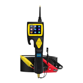
- Page 1 AUTOOL BT280 Electrical System Tester User Manual 用户手册 Smart Multimeter Oscilloscope Relay Active Powered by Injector Set up www.autooltech.com...
- Page 2 执行标准 / Execution standard: GB/T8218-1987...
- Page 3 COPYRIGHT INFORMATION Copyright ● All rights reserved by AUTOOL TECH. CO., LTD. No part of this publication may be reproduced, stored in a retrieval system, or transmitted in any form or by any means, electronic, mechanical, photocopying, recording or otherwise, without the prior written permission of AUTOOL.
-
Page 4: Table Of Contents
TABLE OF CONTENTS Cautions ......................1 Warning ......................1 About BT280 ....................... 2 Overview ......................2 Specifications ....................2 Features ......................2 Product Structure ....................3 Structure diagram.................... 3 Product Use ......................4 Power supply connection ................4 KEY Button operation ..................4 Circuit breaker protection ................ - Page 5 Trailer lights and connection test ..............23 Description Of Accessories................24 Maintenance Service ..................25 Maintenance....................Warranty ......................26 Warranty access....................26 Disclaimer ....................... 26 Return & Exchange Service ................27 Return & Exchange ..................27...
-
Page 6: Cautions
CAUTIONS Warning Before using the instrument, please read this manual carefully for proper operation. Always perform automotive testing in a safe environment. Do not attempt to operate or observe the tool while driving a vehicle, operating or observing the tool will cause driver distraction and could cause a fatal accident. -
Page 7: About Bt280
ABOUT BT280 Overview The BT280 is the newest generation intelligent electrical system circuit tester with 2.4 inch large size LCD screen display. It is dedicated to test all 9V~30V vehicle electrical systems. BT280 is convenient, fast and intelligent! Specifications (320*240 DPI) -
Page 8: Product Structure
PRODUCT STRUCTURE Structure diagram ● A - Probe Tip – Contact the circuit or component for testing. ● B - Front LED Light – Used for lighting in dark working areas or when working at night. ● C - LCD Screen – Display test results. ●... -
Page 9: Product Use
PRODUCT USE Power supply The Probe is powered by the vehicle battery. Connect the RED connection clip to the positive pole of the battery, and the BLACK clip to the negative pole of the battery. The machine will automatically start to enter the working interface, The front LED light will illuminate the test area, which is convenient for operation in the dark area. -
Page 10: Circuit Breaker Protection
NOTE: Do not use the BT280 probe to test the voltage of the house- hold AC Power (such as 110V, 220V plug), it may cause serious injury and property damage for improperly operation. -
Page 11: Working Mode
WORKING MODE This probe adopts a 2.4-inch large color screen and 9-grid interface design, with clear display, simple operation and quick in use. You can select working mode through the navigation buttons and press OK to enter. Smart test The main test functions of this mode: voltage test, resistance test, Positive / negative test. -
Page 12: Multimeter Mode
Resistance Test Result ● How to use: When the probe clip (auxiliary ground lead) is connected to an electrical circuit of resistance and the probe tip is connected to the other end of the resistance, the probe will automatically enter into the resistance display mode and display the resistance values. -
Page 13: Oscilloscope Mode
right are: DC voltage (VDC), resistance (OHM), diode/continui- ty test (DIO), current (AMP), frequency (HZ). How to use Press the “right” button to select the test mode. Press “Left” Button to exit. ● DC voltage (VDC): Connect the probe clip (auxiliary ground lead) to the negative pole, and connect the probe Tip to the measured voltage. -
Page 14: Relay Test
keys to adjust the voltage value). ● “Time” time parameter. ● “HZ” Display test frequency. *Press and hold left key to exit this working mode. Relay test Instructions ● The “VCC” at the top of this interface displays the power supply voltage value. -
Page 15: Component Activation
(5-terminal relay) (Test Results) (4-terminal relay) For example, Test a 5-terminal relay ● Connect the relay test wire to probe. ● Connect the black wire to the relay terminal 30#. ● Connect the green wire to the relay terminal 87A#. ●... - Page 16 Display Value ● VDC: Detected Voltage ● AMP: Detected Current ● VCC: Power Supply Voltage Activation Type ● “MOMENT” Mode: Press “Right” button to select the activation mode to MOMENT mode. Press and hold the “UP” / “Down” button to perform the power supply, Press Release Release “UP”...
-
Page 17: Power Supply
“SET” Circuit Breaker: ● Press “Right” button to select the activation mode to SET mode. Press “UP” / “Down” button to adjust the overload current values from 1A~18A. If the current flowing through the probe is greater than the set value, it will cut off the power and stop activation. -
Page 18: Injector Test
Injector test The probe outputs different pulse signals to the injector, and check the injector spraying status. This function can help diagnose injector conditions. It can work with any fuel pressure tester. Signal Output Mode ● MODE 1: Press “OK” button to activate probe outputs 1 pulse. Pulse width is 250ms. -
Page 19: Positive / Negative Test
Positive / How to use Negative test ● Connect the probe negative clip to the vehicle ground wire, use the probe tip to find the positive / negative wire of the electric circuit system. The following interface is displayed default state: Positive Interface ●... -
Page 20: Setting
Setting ● From setting interface, you can set, sound, language, update, screen, use “UP” and “DOWN” button to select, press “OK” button to change parameters. Press “LEFT” button to save and exit. Online Update ● After in setting interface, select update menu to enter into update mode. -
Page 21: Test Applications
TEST APPLICATIONS Continuity When the probe is in the “Multimeter mode” select resistance test testing function, Use the probe tip with chassis ground of the vehicle or auxiliary ground lead, continuity can be tested on wires and components attached or disconnected from the vehicles electrical system. -
Page 22: Signal Circuit Testing (Oscilloscope Test)
Use an OBD2 Scanner to read out the FAULT CODE (DTC) from Signal circuit the vehicle and found the problem is with some kind of sensor testing circuit, there is a fast way to testing the sensors conditions with (Oscilloscope this probe. - Page 23 ● The LCD screen will display the value of VDC, AMP, and VCC. If the Probe restart for the circuit breaker tripped or the displayed message OVERLOADED on LCD screen, you can adjust the overload current value and repeat the above operation to further activation.
-
Page 24: Activating Components In Vehicle
● The component is a very high current component (such as STARTER MOTOR). NOTE: Activating components The activation mode is only designed for supply powers or in vehicle ground, and cannot be used for any sensitive electronics equipment (such as ECU, sensor module), otherwise there is a risk of burning out components. -
Page 25: Activating Components / Ground
If the probe circuit breaker tripped, it means the probe is overload- ed. This could happened by the following reasons: ● You have connected the probe tip to the direct ground or nega- tive voltage. ● The component you are testing is short circuited. ●... -
Page 26: Checking For Bad Ground Contacts
(To avoid burning out the component, please refer to the specifica- tion and parameter of component and then set the OVERLOAD CURRENT VALUE ) If the probe circuit breaker tripped, it means the probe is overload- ed. This could happened by the following reasons: ●... -
Page 27: Following & Locating Short Circuits
● Press “OK” button to trigger power supply. The RED led light will ON and LCD screen will display values of VDC, AMP and VCC, if the VDC value is almost the same as VCC and AMP value is minimum approach to 0A. it means this is not true ground. -
Page 28: Trailer Lights And Connection Test
Trailer lights ● When the probe is in multimeter or SMART test, connect the and connec- probe auxiliary ground lead to the trailer light, and insert the tion test probe tip into the OBD socket to display the current voltage. With this method you can check the function and direction of the connector and trailer lights. -
Page 29: Description Of Accessories
DESCRIPTION OF ACCESSORIES Name Name BT280 Unit with 6 meters test line Solid copper test probe tip Extension connection line Alligator battery clip Relay test line Probe adapter 25Amp fuse User manual ABS Toolbox... -
Page 30: Maintenance Service
MAINTENANCE SERVICE Our products are made of long-lasting and durable materials, and we insist on perfect production process. Each product leaves the factory after 35 procedures and 12 times of testing and inspec- tion work, which ensures that each product has excellent quality and performance. -
Page 31: Warranty
Disclaimer All information, illustrations, and specifications contained in this manual, AUTOOL resumes the right of modify this manual and the machine itself with no prior notice. The physical appearance and color may differ from what is shown in the manual, please refer to the actual product. -
Page 32: Return & Exchange Service
RETURN & EXCHANGE SERVICE Return & ● If you are an AUTOOL user and are not satisfied with the Exchange AUTOOL products purchased from the online authorized shopping platform and offline authorized dealers, you can return the products within seven days from the date of receipt;... - Page 33 目 录 版权信息 ......................30 版权 ......................... 30 注册商标......................30 注意事项 ......................31 警告......................... 31 产品简介 ......................32 概述 ......................... 32 产品规格......................32 特征 ......................... 32 产品结构 ......................33 结构图 ......................33 产品使用 ......................34 电源连接方式 ....................34 按键操作说明 ....................34 常见界面英文简写说明...
- Page 34 连续性测试 ...................... 46 电路信号测试....................46 激活手中部件....................47 激活车上部件....................49 激活部件/接地 ....................51 检查地线不良接触 ................... 52 追踪和定位短路电路 ..................53 测试拖车灯和连接状态..................53 产品配件 ......................54 维修保养服务 ..................... 55 维修保养......................55 保修服务 ......................56 保修方式......................56 声明 ......................... 56 退换货服务 ......................57 退换货 ......................
-
Page 35: 版权信息
版权信息 版权所有! 未征得深圳市偶然科技有限公司的书面同意, 任何公 版权 ● 司或个人不得以任何形式 (电子、 机械、 影印、 录制或其他形式) 对本说明书进行复制和备份。 本手册专为偶然公司产品的使用 而计, 对于将之用于指导其他设备操作而导致的各种后果, 本公 司不承担任何责任。 因使用者个人或第三方的意外事故, 滥用、 误用该设备, 擅自更 ● 改, 或修理该设备, 或未按偶然公司的操作与保养要求而导致设 备损坏、 遗失所产生的费用及开支等, 偶然公司及其分支机构不 承担任何责任。 正式声明: 本说明书所提及之其他产品名称, 目的在于说明该设 ● 备如何使用, 其注册商标所有权仍属原公司。 本设备供专业技术人员或维修人员使用。 ● 注册商标 偶 然公司已在中国 及 海 外若 干国家 进 行了商标 注 册, 其 标 志 为 ... - Page 36 注意事项 警告 为了避免造成人身伤害或损坏车辆/检测设备, 在使用仪器前 请先阅读说明书并遵守以下安全保护措施 请确保在一个安全的环境中执行诊断测试或服务。 佩戴符合ANSL标准的安全保护眼镜。 将衣服、 头发、 手、 工具、 测试设备等远离所有正在运行或发热 的设备。 由于测试时排出的废气有毒, 请在通风良好的工作区测试车辆 。 请在车轮底部放置阻块, 勿在车辆处于无人看管的状态下测试 。 在点火线圈周围工作时, 要特别小心分器盖、 点火导线和火花塞 。 这些组件在发动机运转时会产生危险高压。 在汽油/化学/电气装置附近放置灭火器以防发生火灾。 把变速箱档位挂停车挡 (自动变速器) 或空挡 (手动变速器) 并 确保拉上手刹。 在点火开关打开或发动机运转时, 请勿连接或断开任何测试设 备。 当按压工具的电源开关, 电池电流、 电压会被直接传导到接触地 面或某些电路, 可能会产生火花。 因此, 请勿在易燃物, 如汽油 或其蒸气附近使用。...
-
Page 37: 产品简介
产品简介 概述 BT280是应用于快速测试所有9V-30V汽车电路系统的工具, 具有高 效先进的测试功能, 能够大大提高用户的工作效率。 产品规格 (320*240 DPI) TFT 真彩显示屏 显示屏 0~60°C (32~140°F) 工作温度 -40~70°C (-40~185°F) 贮藏温度 外接电源 12V或24V汽车蓄电池供电 最小工作电压 最大工作电压 最大测量电压 100V 0.1V 最小测量电压 1 欧姆~200K 欧姆 电阻测量范围 0~18A 电流测量范围 最大持续电流 特征 电压/电阻智能识别 ● 继电器测试 ● 喷油器测试 ●... -
Page 38: 产品结构
产品结构 结构图 探针 接触线路或部件进行测试。 黑暗的工作区或在夜间工作时照明用。 LED灯 液晶显示屏 用于显示测试结果。 识别正极, 负极或开路。 当探针接触正级 红/绿极性 电路, 红色指示灯亮起, 当探针接触负级 检测指示灯 电路, 绿灯亮起。 5键式快捷操作选择工作模式。 操作按钮 辅助接地引线 接地引线辅助测试功能 (负极) 。 扬声器 发出蜂鸣用于警告或提示。 通过用USB线连接PC和探头进行更新。 USB端口 端口 继电器测试线连接端口。 连接器 连接蓄电池夹到汽车蓄电池或延长线。 设备挂置合适的位置方便使用。 多功能挂钩... -
Page 39: 产品使用
产品使用 电源连接 本产品通过汽车蓄电池供电, 将红色蓄电池钳夹到汽车蓄电池的正 方式 极, 黑色蓄电池钳夹到汽车蓄电池的负极。 机器会自动启动进入工 作界面, LED照明灯会照亮探针头的测试区域, 方便在黑暗区域进 行操作。 按键操作 电笔多功能按键采用最新科学设计, 共有5个物理按键, 包括: 说明 “左键” 、 “右 键” 、 “上键” 、 “下键” 、 “OK键” 。... -
Page 40: 常见界面英文简写说明
在不同的功能界面, 五个按钮执行的功能也不完全相同。 左键 - 导航键或退出键 (进入功能菜单后按左键为退出功能) 。 ● 右键 - 导航键。 ● 上键 - 导航键或电压输出, 数值调节 (激活功能菜单向上按键为 ● 正向电压输出功能) 。 下键 - 导航键或电压输出, 数值调节 (激活功能菜单向下按键为 ● 反向电压导通功能) 。 OK - 确认键。 ● 常见界面 VDC: 直流电压 MOMENT: 瞬间模式 ● ● 英文简写 VCC:... -
Page 41: 智能测试
工作模式及测试应用 本产品采用2.4寸大彩屏9宫格界面设计, 显示清晰, 操作简单, ● 使用快捷, 您可以通过导航按键进行选择, 按 【OK】 键进入。 智能测试 该模式主要测试功能: 电压测试, 电阻测试, (对应显示模式, VDC, OHM, AMP) 。 主要用于快速测试, 不用切换不同的测试模式。 自动 识别被测信号, 智能判断是电压还是电阻, 然后进行不同功能的显 示。 电压显示 使用方法: 当电笔夹子 (辅助接地引线) 接入地线, 探头上感应 ● 到电压时会自动进入电压显示模式, 并实时显示当前的电压。 如图显示 “BATT” 是电瓶供电电压为11.2V, “VDC” 为当前测试 ●... -
Page 42: 万用表功能
电阻显示 使用方法: 当电笔夹子 (辅助接地引线) 接入线路电阻一端, 探 ● 头接入电阻的另外一端, 电笔会自动切入电阻显示模式, 并实时 显示当前线路的电阻值。 模式 单位 电源正负极功能 当系统检测到的电压与电源有±0.8V的偏差时, 红色LED灯亮, ● VDC显示当前电源, 喇叭规律性发声; 当系统检测到电源负极时 , 绿色LED灯亮, 同样地, 喇叭会规律性发声。 万用表功能 功能区域 界面最下方是功能区域, 从左到右依次是: 直流电压 (VDC) , 电 ● 阻 (OHM) , 二极管/通断测试 (DIO) , 电流 (AMP) , 频率 (HZ) 。... -
Page 43: 示波器
电阻 (OHM) : 将电笔的夹子 (辅助接地引线) 接入被测电阻一 ● 端, 探头接被测电阻的另外一端。 二极管/通断测试 (DIO) : 当电笔夹子 (辅助接地引线) 和探头接 ● 入的是普通二极管, 界面显示该二极管的道通电压, 并提示该二 极管的正负极, 当接入导线时会显示该导线的阻值, 如果声音打 开蜂鸣器会发声。 电流 (AMP) : 显示外部电能流入电笔的电流值。 ● 频率 (HZ) : 显示被测信号的频率和对应的占空比值。 ● 按键使用 使用 “右键” 按键进行功能的选择。 ● 使用 “左键” 退出。 ●... - Page 44 继电器 操作说明 此界面最上方 “VCC” 实时显示电源供电电压值, 白色图示部分 ● 显示有2种常见的汽车用继电器框图 (5端子继电器和4端子继电 器) , 下面是30#引脚的连接状态, 此状态是未连接状态, “左键 ” 进行移动选择, “确认键” 查看这2种不同继电器的接线效果图 。 (5 端子继电器) (测试结果) (4 端子继电器) 例如 : 测试 5 端子继电器 1) 连接好继电器测试线 ●...
-
Page 45: 部件激活
2) 将黑色导线连接到继电器端子 30 3) 将绿色导线连接到继电器端子 87A (绿色指示灯会亮) 4) 将红色导线连接到继电器端子 87 5) 将辅助接地导线 (电笔负极) 连接到端子 86 6) 将电笔探针连接到继电器端子 85 7) 按上键触发测试 (红色指示灯应点亮, 绿色指示灯应熄灭) 8) 松开按钮, 红色指示灯熄灭, 绿色指示灯点亮 * 底部同时会显示继电器测试结果提示信息。 部件激活 注意 激活模式仅仅设置于供电或者供地, 不能随便用于敏感的电气 设备 (比如 ECU, 传感器模块) , 否则有烧毁的风险。 在未完全禁用系统之前, 切勿在任何 SRS( 气囊 ) 系统上执行任 何测试。... - Page 46 模式切换区域 界面最下方是功能选择区域, 共有4个功能, 有设置切换过载电 ● 流大小的功能, 还有SET( 过载电流设置) 功能等。 另外还有3种 激活模式, 分别为MOMENT(瞬间激活), L ATCH (锁定激活) , PULSE( 脉冲激活 )。 三种激活模式 “MOMENT” 瞬间激活 : ( 单次供电) ● 按住 “上键” 正向激活, 此时电笔探头是电源电压, VDC会显示, AMP显示通过的电流。 松开 “上键” 取消正向激活, 电笔探头没有电压, VDC显示0V。 如果 “下键” 被按下, 电笔探头电源与负极相连, VDC显示0V, AMP显示通过的电流。...
-
Page 47: 5V供电模式
0~5V供电模式 0-5V供电功能可以有效助力检查与ECU的接线。 在您使用电压表 ● 或欧姆表检查传感器后, 如果仍然存在问题, 您可以模拟传感器 输出的电压以验证去往ECU的接线, 使用OBD扫描仪可以查看 E C U 的 检 测 结 果 。 设 备可以 选 择 从0 ~ 5 V 的 供 电 电 压(电 流 <100mA) , 以0.5V为增量。 界面显示分为2个部分, 左边的显示 设置的电压 (使用 “上键” 和 “下键” 按键来增加或者减小电压的 设置值)... - Page 48 喷油嘴测试原理 电笔通过输出不同的脉冲信号, 然后把输出的信号接入到喷油 ● 嘴上, 观察喷油嘴的好坏。 信号模式输出 共 有4 种脉 冲 信号模 式, 通 过“上键 ”和“下键 ” 进 行模 式 选 择, “OK” 键产生对于模式的脉冲信号。 模式 1: ● 电笔产生250ms的高脉冲, 按一下 “OK” 键, 电笔输出一次。 模式 2: ● 电笔产生高7ms, 低20ms的脉冲, 总共持续1.4s, 通过 “OK” 按 键来启动。...
- Page 49 正负极测试 使用方法 电笔的负极夹子接入汽车地线上, 电池的探头可以尝试寻找汽 ● 车电源的正极和负极。 默认状态没有找到正负极的时候显示如下 界面: 电笔找到正极界面 上部分实时显示正极性的电压值, 下部分提示框显示 “正极 (+)” 。 ● 电笔找到负极界面 上部分显示接地图标, 下部分提示框显示 “负极 (-)” 。 ●...
-
Page 50: 系统设置
系统设置分为五项。 (声音, 语言, 升级, 显示风格, 关于) 系统设置 声音 使 用上下键 操作选 择, 当光标“ >”选中“声音”选 项时, 使 用 ● “OK” 键切换打开或关闭电笔的声音, 按 “左键” 保存退出。 发 声是电笔内部蜂鸣器输出声音, 应用于按键操作、 报警声音以及 其他提示声音 (其它选项采用相同方式操作即可) 。 在线升级 使用上下键操作选择[ 升级 ]菜单, 按下 “OK” 进入升级模式后, ● 界面显示如下图。 此时, 接入USB连线, 打开电脑端升级软件, 进 行升级。... -
Page 51: 测试应用案例
测试应用案例 连续性测试 当设备处于万用表电阻模式时, 将探针接触汽车底盘或接地辅助线 , 可以连续性测试汽车电路系统的线路或部件, 连接或者断开状态。 当探针接地良好时, 液晶显示屏会显示 “0.0Ω” , 同时绿色的LED 指 示灯也会亮起。 如果提示音功能已经开启, 蜂鸣器会同时发出短提 示音。 在其他情况下, 液晶屏将只显示阻值。 ● 如果阻值大于200千欧, 液晶屏将显0L。 ● 还有另外一种方法可以证明接地还是电瓶的连续性。 用电源开关连 接供电, 如果断路器跳闸, 说明此连接是一个良好的低电阻连接。 注意 您可以使用锋利的探针刺破电线上的绝缘壁, 如此您无需断开 任何线路便可以测试该电路。 一旦从汽车电脑中发现故障码, 并且意识到该故障码是由于汽车电 电路信号 测试 路传感器系统所导致, 以下举例的方法可以快速地测试并验证该故 障码。... -
Page 52: 激活手中部件
例如, 您怀疑车辆的M.A.P.传感器出现故障。 那么, 可通过下 列方式逐步测试: 进入设备的示波器功能, 用探针接触汽车底盘或接地辅助线。 ● 连接真空泵与M.A.P.传感器。 ● 将探针接触到M.A.P.传感器正极, 并观察液晶显示屏, 正常情况 ● 下显示内容应为正弦波形。 启用真空泵。 ● 释放真空泵并观察液晶屏读数。 ● 注意 若液晶显示屏显示波形异常, 即该传感器有故障。 激活手中 注意 部件 激活模式仅仅设置于供电或者供地, 不能随便用于敏感的电气 设备 (比如ECU, 传感器模块) , 否则有烧毁的风险。 在未完全禁用系统之前, 切勿在任何ECU, SRS (气囊) , 系统上 执行任何测试。 随意施加电压到车辆电路会引起车辆电子部 件的损坏,... - Page 53 进入设备部件激活功能界面, 将探针接触接地辅助线, 您可以立即 激活手中部件, 从而测试它们的功能。 3种激活方式, 假设过载电流设置到2A。 1 )( M O M E N T ) ,瞬 间 激 活,此 时 激 活 界 面 下 方 黄 色 选 中 ● “MOMENT” 模式, 按压 “UP” 键不释放, 红色LED灯亮起, 表 明此时电池正极接入电笔探头, 电流将会从电瓶正极流入探针, 通过探针流入部件的正极,...
-
Page 54: 激活车上部件
若设备熄灭, 或者断路器跳闸, 说明本产品过载, 此种现象可能由如 下原因导致: 您直接将探针接触到负极或地线。 ● 您所测试的部件存在短路情况。 ● 该部件是高电流部件 (如启动马达等) 。 ● 激活车上 3种激活方式, 假设过载电流设置到2A。 部件 1 )( M O M E N T ) ,瞬 间 激 活,此 时 激 活 界 面 下 方 黄 色 选 中 ●... - Page 55 3) (PULSE) , 脉冲式激活, 按一次 “上键” 会有1s激活, 然后自动 ● 断开1s, 重复进行, 部件会周期性激活或者关闭。 如果再次按 “上 键” , 则退出 “PULSE” 激活模式。 注意 如果过载电流已经设置到最小值1A, 激活时发现电笔断路或者 跳闸, 可能是设备短路到地, 需要排查部件问题。 如果过载电流已经设置到最大值18A, 激活时发现电笔断路或者 跳闸, 可能由于该部件是高电流部件 (如启动马达等) 。 不能随便用于敏感的电气设备 (比如ECU, 传感器模块) , 否则有 烧毁的风险。 如果断路器跳闸, 说明本产品过载, 此种现象可能由如下原因导致 :...
-
Page 56: 激活部件/接地
激活部件/ 有3种激活方式, 假设过载电流设置到2A。 接地 当设备处于部件激活模式时, 将探针接触至部件负极, 此时激活界 面VDC显示的电压接近VCC显示的电压值, 表明电源已经加载到部 件上, 要激活该部件可以使用下面三种方式进行。 1 )( M O M E N T ) ,瞬 间 激 活,此 时 激 活 界 面 下 方 黄 色 选 中 ● “MOMENT” 模式, 按压 “DOWN” 键不释放, 绿色LED灯亮起, 表明此时电源地线接入电笔探头,... - Page 57 注意 使用此功能时, 如果您探触一个被保护的电路并搭上地线, 车辆 的保险丝可能熔断或跳闸。 检查地线 使用探针探测可疑的地线。 不良接触 当设备处于部件激活模式时, 假设过载电流设置到最小值 1A。 (MOMENT) , 此时激活界面下方黄色选中 “MOMENT” 模式, ● 按压 “UP” 键不释放, 红色LED灯亮起, 表明此时电池正极接入 电笔探头, 电流将会从电瓶正极流入探针, 通过探针接触被测线 路, 如果激活界面中 “VDC” 实时显示探针的电压接近VCC电压, AMP显示的流过电笔的电路接近0, 说明不是真正的地线, 如果 发现电笔显示 “设备过载” , 说明有可能是地线。 注意 请牢记, 高电流部件例如启动马达等也会使断路器跳闸。...
-
Page 58: 测试拖车灯和连接状态
追踪和定位 大多数情况下, 短路会表现为一个保险丝熔断或电气保护装置跳闸 短路电路 (例如断路器跳闸) 。 这是检查短路开始的最佳位置。 将熔断的保险丝从保险盒中取出。 ● 用探针去激活并供给每个保险丝触点电流。 ● 断路器跳闸的线路即为短路线路。 ● 记录下线路的编号或颜色。 ● 尽可能远地跟随导线来追踪线束。 ● 示例 : 如果您正在追踪刹车灯的短路线路, 首先线束必须穿过导线的 ● 门槛, 找到该线的颜色或编号并标记它。 用探针与绝缘处接触, 使用 “MOMENT” 或者 “LATCH” 模式, 按 ● “上键” 给线路通电激活。 如果电笔过载, 表示已经验证了该线路短路。 剪断该条线路并用 ● 探针分别给导线的两端加电。 再次使电笔过载保护的一端即为 短路端,... -
Page 59: 产品配件
产品配件 名称 名称 主机 6 米长测试线 全铜测试探针 双通测试连接线 鳄鱼夹电瓶连接线 继电器测试线 探头适配器 20Amp 熔断保险管 操作说明书... -
Page 60: 维修保养
维修保养服务 您所拥有的AUTOOL产品选用持久耐用的材料, AUTOOL坚持精益求 精的生产工艺, 每一件产品出厂都经过35道工序及12次质检工作, 从 而确保每一件产品都拥有卓越的品质及性能。 所以您的AUTOOL产 品值得您定期维护保养, 使其将能够长期稳定地工作。 维护保养是为了保持产品性能和外观, 我们建议您仔细阅读以下产 维修保养 品保养指南: 注意不要将产品与粗糙表面摩擦或揉搓产品, 特别是钣金外壳。 ● 对产品中需要紧固和连接的部位经常进行检查, 如发现松动应及 ● 时紧固, 以保证产品的安全运行。 对与各种化学介质接触的产品 外部和内部零件要经常进行除锈、 喷漆等防腐处理, 以提高产品 的抗腐蚀能力, 延长产品的使用寿命。 遵守安全操作规程, 不超负荷使用产品。 产品的安全防护装置齐 ● 全可靠, 及时消除不安全因素。 电路部分彻底检查, 老化电线要 及时更换。 定期清洗和更换油泵、 滤油器等易耗部件; 调整各部位配合间隙... -
Page 61: 保修方式
AUTOOL主机自客户签收日起享有3年保修期。 其所含附件自客户签 收日起享有1年保修期。 根据具体的故障情况对产品进行免费修理或更换; 保修方式 ● 我方保证所有更换的部件、 附件或产品都是全新; ● 在客户收到产品90天内出现故障同时提供视频和图片, 我方承 ● 担运费并免费提供相应配件给客户更换。 收到产品超过90天, 客 户承担相应的费用, 我方免费提供配件给客户更换; 以下情况不在免费保修范围: 非正规渠道购买AUTOOL的产品; ● 未按产品说明书要求使用和维护造成的损坏; ● 在AUTOOL, 我们为精湛的设计和卓越的服务感到自豪。 我们很乐 意为您提供更多的支持或服务。 偶然公司保留更改产品设计与规格的权利, 届时恕不另行通知。 实 声明 物外观与颜色可能与说明书中显示的有差别, 请以实物为准。 我们 已尽最大努力力求使书中所有描述准确, 但仍难免有不妥之处。 如 有疑问, 请联系经销商或偶然售后服务中心。 本公司对产品拥有最 终解释权, 不承担任何因误解而产生的后果。... -
Page 62: 退换货服务
退换货服务 退换货 如 果 您 对从 线 上 授 权 购 物 平台和 线 下 授 权 经 销 商 所 购 买 的 ● AUTOOL产品不满意, 根据 《AUTOOL全球销售条款》 , 您可以自 收到产品之日起七日内退货; 或者在产品交付之日起的30日内调 换等值的其他产品。 退回及调换的产品必须处于完全可销售状态, 并附上相关销售单 ● 单据, 所有相关配件、 纸质发票 (如有) 。...
Need help?
Do you have a question about the BT280 and is the answer not in the manual?
Questions and answers