SolaX Power X1 Series User Manual
Microinverter 2 in 1
Hide thumbs
Also See for X1 Series:
- User manual (63 pages) ,
- Quick installation manual (3 pages) ,
- Quick installation manual (2 pages)

Subscribe to Our Youtube Channel
Related Manuals for SolaX Power X1 Series


Summary of Contents for SolaX Power X1 Series
- Page 1 X1-Microinverter 2 in 1 800 W / 900 W / 1000 W / 1200 W User Manual Version 1.0 www.solaxpower.com eManual in the QR code or at http://kb.solaxpower.com/...
- Page 3 STATEMENT Copyright Copyright © SolaX Power Network Technology (Zhejiang) Co., Ltd. All rights reserved. No part of this manual may be reproduced, transmitted, transcribed, stored in a retrieval system, or translated into any language or computer language, in any form or by any means without the prior written permission of SolaX Power Network Technology (Zhejiang) Co., Ltd.
- Page 4 About This Manual Scope of Validity This manual is an integral part of X1-Microinverter 2 in 1 Series. It describes the installation, electrical connection, commissioning, maintenance and troubleshooting of the product. Please read it carefully before operating. X1-Micro 800 X1-Micro 900 X1-Micro 1000 X1-Micro 1200 Note:...
- Page 5 Conventions The symbols that may be found in this manual are defined as follows. Symbol Description Indicates a hazardous situation which, if not avoided, DANGER will result in death or serious injury. Indicates a hazardous situation which, if not avoided, WARNING could result in death or serious injury.
-
Page 6: Table Of Contents
Table of Contents Safety ......................1 1.1 General Safety ........................1 1.2 Safety Instructions of PV, Inverter and Grid ...............1 1.2.1 Safety Instructions of PV ..................2 1.2.2 Safety Instructions of Microinverter ..............2 1.2.3 Safety Instructions of Utility Grid ..............4 1.2.4 Inverter backfeed current onto the array ............4 1.2.5 Safety Instructions of AC trunk cable .............4 Product Overview ..................5... - Page 7 5.2 Troubleshooting .........................26 5.3 On-Site Inspection (for qualified installaer only) ............28 5.4 Maintenance ........................29 5.4.1 Maintenance routines ..................29 5.4.2 Upgrading Firmware ....................30 Decommissioning ..................32 6.1 Disassembling the Microinverter .................32 6.2 Packing the Microinverter ....................32 6.3 Transportation and Storage ....................33 6.4 Disposal of the Microinverter ..................33 Technical Data ..................34 Appendix ....................36 8.1 INSTALLATION MAP ......................36...
-
Page 9: Safety
Safety General Safety The series inverter has been meticulously designed and thoroughly tested to comply with the relevant state and international safety standards. Nevertheless, like all electrical and electronic equipment, safety precautions must be observed and followed during the installation of the inverter to minimize the risk of personal injury and ensure a safe installation. -
Page 10: Safety Instructions Of Pv
Safety 1.2.1 Safety Instructions of PV DANGER! Lethal danger from electric shock due to the PV! • Never touch the positive or negative pole of PV connecting device. Touching both of them at the same time is prohibited as well. •... - Page 11 Safety WARNING! • The installation place should be away from humid or corrosive substance. Avoid installation near extremely hot/cold environment. • Please consult the manufacutuer for non-standard installation conditions. • Make sure that the microinverter is installed under the PV module in case of direct exposure to UV, rain and other harmful weather events.
-
Page 12: Safety Instructions Of Utility Grid
Safety 1.2.3 Safety Instructions of Utility Grid NOTICE! • Only with permissions of local utility grid company, the microinverter can be connected to the grid. • The installer must provide Over Current Protection Devices (OCPD) and external disconnect switches. 1.2.4 Inverter backfeed current onto the array NOTICE! This requirement protects against overloading of array wiring due to backfeed currents... -
Page 13: Product Overview
Product Overview Microinverter System Description A microinverter system is composed of PV grid-connnected microinverters, PV modules, and grid. Microinverter data are transmitted to SolaX monitoring platform SolaXCloud. Figure 2-1 System overview diagram X1-Microinverter 2 in 1 series The X1-Microinverter 2 in 1 series manages system energy. Microinverters convert the direct current power generated from the PV modules into grid-compatible AC current. - Page 14 Product Overview Tracking (MPPT). The X1-Microinverter 2 in 1 is integrated with MPPT, which means that even though a PV module runs abnormally or is shaded, other modules won't be affected and can operate the unshaded string at maximum efficiency point. This function plays an important role to improve the efficiency of a photovoltaic (PV) generation system.
-
Page 15: Highlights
Product Overview Highlights • Max output power up to 1200VA with two independent input channels(MPPT) • Up to 20A DC input current to be compatible with the high power PV module • Built-in industrial grade Wi-Fi module for high reliability •... -
Page 16: Dimensions
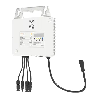
Product Overview 2.3.2 Dimensions 260 mm 40 mm Figure 2-3 Dimensions 2.3.3 Terminals of Microinverter Figure 2-4 Terminals of Microinverter Table 2-1 Description of terminals Item Description Spare ground For standby earth connection. cable clip... -
Page 17: Symbols On The Label And Microinverter
Product Overview PV terminal For PV connection. Indicator Show the status of the device. Antenna To receive and transmit WiFi signal. AC terminal For AC connection. A connection component for electrical devices which Earth lug need grounding (perferred grounding method). 2.3.4 Symbols on the Label and Microinverter Table 2-2 Description of symbols... -
Page 18: Preparation Before Installation
Preparation before Installation Unpacking and Inspection 3.1.1 Unpacking • The microinverter undergoes 100% testing and inspection before shipping from the manufacturing facility. However, transport damage may still occur. Before unpacking the Microinverter , please verify that the model and outer packing materials for damage, such as holes and cracks. -
Page 19: Packing Lists
Preparation before Installation Packing Lists Microinverter Installation Map Make sure N for North Panel type: Customer information: Gateway series number: Azimuth: Tilt: Sheet_of_ COLUMN Installation map × 1 Inverter × 1 Documents Sold separately: AC trunk port disconnect 1.2m/2m/2.4m AC trunk AC trunk end cap AC trunk connector tool... -
Page 20: Installation Angel Requirement
Preparation before Installation • Do not install the microinverter in areas near combustibles and antenna; • Install all microinverters and DC connectors under the PV modules. • Avoid direct exposure to UV, rain and other harmful weather events. • Avoid electromagnetic interference in case of the malfunction of electronic equipment. -
Page 21: Tools Requirement
Preparation before Installation Tools Requirement 3.4.1 Recommended Equipment Installation tools include but are not limited to the following recommended ones. If necessary, use other auxiliary tools on site. Cable tie Multimeter Measuring tape Utility knife Torque screwdriver Marker (Phillips head: M4) Diagonal pliers Allen key Wire cutter... -
Page 22: Ac Branch Circuit Capacity
Preparation before Installation AC Branch Circuit Capacity X1-Microinverter 800/900/1000/1200 can be used with the provided AC Trunk Cable and AC Trunk Connectors. The maximum number of microinverters on each AC branch is listed as follows: Maximum over X1-Micro 800 X1-Micro 900 current protection device 8@220V... -
Page 23: Installation
Installation Accessories Description 1.2m/2m/2.4m AC trunk cable... -
Page 24: Microinverter Installation
Installation Description DC extension cable (if necessary) AC trunk connector AC trunk end cap AC trunk port disconnect tool Female connector Male connector AC end cable NOTICE! • The above accessories are not included in the package and need to be purchased separately. - Page 25 Installation Step 1: Rail Installation A) The installer has to install the rails on the roof and fix them with screws to ensure a stable installation environment for microinverters. Step 2: Plan the Number and Installation Location of Microinverters A) Arrange the installation number and location of each microinverter according to the layout of the photovoltaic system.
- Page 26 Installation Step 4: Place AC Trunk Cable on the Rail A) Place the AC trunk connector on the rail inwards (as shown below) and band it with cable ties. NOTICE! • In order to better fix the AC trunk cable, it is recommended to use more cable ties to band the AC trunk cable.
- Page 27 Installation D) Repeat this step in sequence. E) Cover vacant AC ports with AC trunk end cap. Male Step 5: AC Trunk Cable Connection A) Plug the AC connector of the microinverter into the trunk cable connector. The connection is completed when you hear a "click". Click NOTICE! •...
- Page 28 Installation X X X X X X X X X X X X X X X X X X X X X X X X X X X X X X X X paste Step 7: Grounding methods We provide two grounding methods for this series of microinverters. If the earth lug doesn't touch the rail or the rail is not on the ground, please try method 2.
-
Page 29: Microinverter System Initiating
Installation connects PV terminals of each microinverter to the corresponding DC cable of PV module. NOTICE! • If the pannels are too far from the microinverter, please use extended DC cable for connection. B) Cover the PV modules above the microinverters and fix the PV panels. C) Then connect it to the local grid. -
Page 30: Setup Monitoring System
Installation » Make sure the microinverter is installed under the PV modules; » Make sure all the connectors are free of water. Step 1: First turn on the AC breaker on the branch circuit and then the main AC breaker of the house. - Page 31 Installation Fill in your registration Email, input the Verification code, and enter your password to create the account. Log in the App after registration finished. Figure 4-4 Login NOTICE! • App registration via Create a new account is for end-users. If you want to apply for an account of agent, please send an email to: service@solaxpower.com.
- Page 32 Installation Figure 4-5 Creating the site Allow SolaxCloud to access your system location, fill in site name (self-defined), system size (the total PV power of the system; please check the information with the installer) and add device by scanning the code on Pocket WiFi. Figure 4-6 Site information NOTICE! •...
- Page 33 Installation Figure 4-7 DST Enter your WiFi account and password. Start to configure the device network. DHCP is enabled by default to distribute IP address automatically. 5GHz network is not supported. Figure 4-8 Wi-Fi configuration NOTICE! Pocket WiFi V3.0 Installation manual •...
-
Page 34: Troubleshooting And Maintenance
Troubleshooting and Maintenance LED Indicator Status LED Indicator Status Description Microinverter startup. If the light flashes once in 1s, flashes in 10s or still flashes Yellow light flash after 10s, microinverter startup fails or DSP firmware is upgrading. Yellow light steady on Microinverter standby/self-checking. - Page 35 Troubleshooting and Maintenance Code Faults Diagnosis and solutions Grid Voltage Out of Range. -Check if the mains cable is loose. IE0003 GridVoltFault -Wait for a while and the system will reconnect when the utility is back to normal. -Or seek help from us. Grid Frequency Out of Range.
-
Page 36: On-Site Inspection (For Qualified Installaer Only)
Troubleshooting and Maintenance Code Faults Diagnosis and solutions PV Direction Fault. IE0030 PvConnDirFault -Check if the PV+/- sides are connected correctly. -Or seek help from us. Relay Fault. -Check the grid connection. IE0031 GridRelayFault -Restart the inverter. -Or seek help from us. PowerTypeFault: -Check the version of Module and DSP. -
Page 37: Maintenance
Troubleshooting and Maintenance Maintenance Regular maintenance is required for the Microinverter. The table of “Proposal of Maintenance” below lists the operational maintenance for expressing the optimum device performance. More frequent maintenance service is needed in the worse work environment. Please make records of the maintenance. WARNING! •... -
Page 38: Upgrading Firmware
Troubleshooting and Maintenance 5.4.2 Upgrading Firmware Upgrade precautions WARNING! • If the DSP and Integrated WiFi Module firmware need to be upgraded, please note that WiFi Module firmware firmware must be upgraded first, then DSP firmware! • Please make sure that the category format is correct, do not modify the firmware file name. - Page 39 Troubleshooting and Maintenance Select Remore Upgrade, choose the microinverter you want to upgrade and click the upgrade icon. If you need batch upgrade, please select Equipment Classification, Applicable Model and Update program first. Then choose the models you want to upgrade, and click Batch Upgrade.
-
Page 40: Decommissioning
Decommissioning Disassembling the Microinverter To disassembling the microinverter » De-energize the AC breaker. » Dismount the PV module from the bracket for meter detection. » Use a meter to check the DC cables and make sure no current flow exists in the wires between microinverter and module. -
Page 41: Transportation And Storage
Decommissioning Transportation and Storage If the microinverter is not put into use immediately, the transportation and storage requirements needs to be met: Transportation • Observe the caution signs on the packaging of microinverter before transportation. • Wear protective gloves when carrying the equipment by hand to prevent injuries. Storage •... -
Page 42: Technical Data
Technical Data • DC Input Model X1-Micro 800 X1-Micro 900 X1-Micro 1000 X1-Micro 1200 Max. recommended DC power [W] 320-540+ 360-600+ 400-670+ 400-670+ Max. PV voltage [d.c. V] MPPT voltage range [d.c. V] 22-60 Max. PV current [d.c. A] 2 × 15 2 ×... - Page 43 Technical Data *2 Refer to local rules and regulations for the specific number of microinverters per branch. • Efficiency, Safety and Protection Model X1-Micro 800 X1-Micro 900 X1-Micro 1000 X1-Micro 1200 MPPT efficiency 99.9% 99.9% 99.9% 99.9% Maximum efficiency 96.5% 96.5% 96.5% 96.5%...
-
Page 44: Appendix
Appendix INSTALLATION MAP... -
Page 45: Wiring Diagram - 230Vac Single Phase
Appendix WIRING DIAGRAM – 230VAC SINGLE PHASE... -
Page 46: Wiring Diagram -120Vac / 240Vac Split Phase
Appendix WIRING DIAGRAM –120VAC / 240VAC SPLIT PHASE:... -
Page 47: Wiring Diagram 230Vac/400Vac Three-Phase
Appendix WIRING DIAGRAM 230Vac/400Vac Three-Phase... -
Page 48: Wiring Diagram 120Vac/208Vac Three-Phase
Appendix WIRING DIAGRAM 120Vac/208Vac Three-Phase... - Page 49 Contact Information UNITED KINGDOM AUSTRALIA Unit C-D Riversdale House, Riversdale 21 Nicholas Dr, Dandenong South VIC 3175 Road, Atherstone, CV9 1FA +61 1300 476 529 +44 (0) 2476 586 998 service@solaxpower.com service.uk@solaxpower.com TURKEY GERMANY KIZILSARAY MAH. 76 SK. LATİF AYKUT Am Tullnaupark 8, 90402 Nürnberg, İŞMERKEZİ...
- Page 50 Add: Unit C-D Riversdale House, Riversdale Road, Atherstone, CV9 1FA Tel: +44 (0) 2476 586 998 E-mail: service.uk@solaxpower.com Authorised Representative (AUS) Name: SolaX Power AUS Pty Ltd Add: 21 Nicholas Dr, Dandenong South VIC 3175 Tel: +61 1300 476 529 E-mail: service@solaxpower.com...
- Page 51 Warranty Registration Form For Customer (Compulsory) Name Country Phone Number Email Address State Zip Code Product Serial Number Date of Commissioning Installation Company Name Installer Name Electrician License No. For Installer Module ( If Any ) Module Brand Module Size(W) Number of String Number of Panel Per String Battery ( If Any )
- Page 52 CE Statement SolaX Power Network Technology (Zhejiang) Co., Ltd. declares that this X1-Microinverter 2 in 1 is in compliance with the essential requirements and other relevant provisions of Directive 2014/53/EU. In accordance with Article 10(2) and Article 10(10), this product allowed to be used in all EU member states.
- Page 53 SolaX Power Network Technology (Zhejiang) Co., Ltd. Add.: No. 288, Shizhu Road, Tonglu Economic Development Zone, Tonglu City, Zhejiang Province, 310000 P. R. CHINA Tel.: +86 (0) 571-5626 0011 E-mail: info@solaxpower.com 320101099101 Copyright © SolaX Power Network Technology (Zhejiang) Co., Ltd. All rights reserved.
Need help?
Do you have a question about the X1 Series and is the answer not in the manual?
Questions and answers