Table of Contents
Advertisement
Quick Links
CAUTION: To Reduce The Risk Of Injury, User Must Read
And Understand Operator's Manual. Save These Instructions
For Future Reference.
For questions / comments, technical assistance or repair
parts - Please call toll free at: 1-877-684-8912 (Monday -
Friday 8am - 6pm EST.)
16" Scroll Saw
240-3726
OPERATOR'S MANUAL
Page 1
Advertisement
Table of Contents

Related Manuals for Performax 240-3726


Summary of Contents for Performax 240-3726
- Page 1 16" Scroll Saw 240-3726 OPERATOR’S MANUAL CAUTION: To Reduce The Risk Of Injury, User Must Read And Understand Operator’s Manual. Save These Instructions For Future Reference. For questions / comments, technical assistance or repair parts - Please call toll free at: 1-877-684-8912 (Monday - Friday 8am - 6pm EST.)
-
Page 2: Table Of Contents
TABLE OF CONTENTS Safety Symbols ................................Page 2 Safety Instructions ............................... Page 3 Overview ..................................Page 8 Speci cations ................................Page 9 Contents ..................................Page 10 Assembly ................................... Page 11 Operation ................................... Page 19 Maintenance ................................Page 23 Troubleshooting ................................. Page 25 Replacement parts list ............................... -
Page 3: Safety Symbols
SAFETY SYMBOLS Some of these following symbols may be used on this tool. Please study them and learn their meaning. Proper interpretation of these symbols will allow you to operate the tool better and safer. Symbol Name Designation / Explanation Volts Voltage Amperes... -
Page 4: Safety Instructions
SAFETY INSTRUCTIONS The purpose of safety symbols is to attract your attention to possible dangers. The safety symbols and the explanations with them deserve your careful attention and understanding. The symbol warnings do not, by themselves, eliminate any danger. The instructions and warnings they give are no substitutes for proper accident prevention measures. WARNING: Be sure to read and understand all safety instructions in this manual, including all safety alert symbols such as “DANGER,”... - Page 5 SAFETY INSTRUCTIONS Safety is a combination of using common sense, staying GENERAL SAFETY RULES alert, and knowing how your scroll saw works. Read this • MAINTAIN TOOLS WITH CARE. Keep tools sharp and manual to understand this scroll saw and how to use clean for best and safest performance.
- Page 6 SAFETY INSTRUCTIONS • Do not position your ngers where they could contact the line you are cutting. the blade if the workpiece should unexpectedly shift or • Do not use if blade protect board is damaged or missing. your hand should slip. •...
- Page 7 SAFETY INSTRUCTIONS this plug to a 2-pole receptacle as shown in Sketch B, if MINIMUM GAUGE (AWG) a properly grounded outlet is not available. The temporary EXTENSION CORDS (120V use only) adapter should be used only until a properly grounded Amperage rating Total length outlet can be installed by a quali ed electrician.
- Page 8 SAFETY INSTRUCTIONS between sides of blade. A thicker blade has more rigidity • Dust Blower: The dust blower keeps the line of cut on the and stronger teeth. A narrow, thick blade is used to make workpiece clean for more accurate scroll cuts. For best curves and a wide, thin blade is used to make long, results, always direct air ow at the blade and...
-
Page 9: Overview
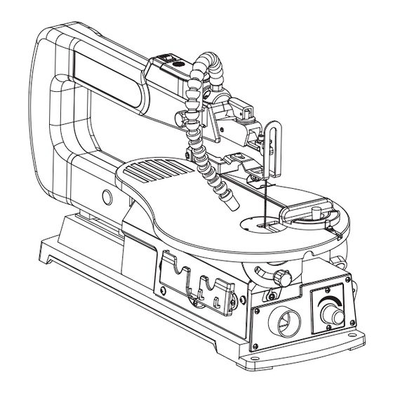
OVERVIEW LED light switch Blade tension lever Upper blade holder Saw arm Dust blower Saw blade Lower blade holder Drop foot lock knob Work table Base Storage compartment Variable speed knob Angle gauge Dust extraction port Battery compartment cover Blade protect board Drop foot Rubber bearing cover LED light... -
Page 10: Speci Cations
SPECIFICATIONS 120 V~ 60 Hz 1.2A Motor Blade speed 400-1600 SPM Blade length 5-1/4" Blade width 3/32" Table size 15" x 10" (380 x 250mm) Table tilting angle 0-45° (left) & 0-15° (right) Max. cutting depth 2" Max. cutting width 16"... -
Page 11: Contents
CONTENTS The following items are included with your 16" Scroll Saw: PART DESCRIPTION QUANTITY PART DESCRIPTION QUANTITY Scroll Saw Assembly Hex nut Miter Gauge Hex bolt Blade Clamp Screw Spring washer 2 mm Hex Key Flat washer Rubber foot WARNING: The use of attachments or accessories not listed in this manual might be hazardous and could cause serious personal injury. -
Page 12: Assembly
ASSEMBLY UNPACKING YOUR SCROLL SAW • Unpack all parts and lay them on a at, stable surface. • Remove all packing materials and shipping devices if applicable. • Make sure the delivery contents are complete and free of any damage. If you nd that parts are missing or show damage do not use the product but contact your dealer. - Page 13 ASSEMBLY WARNING: To avoid serious personal injury from unexpected tool movement, always secrurely mount scroll saw to a workbench. CAUTION: All bolts should be inserted from the top. Install the washers and nuts from the underside of the bench. • Place scroll saw on workbench. Using the saw base as a pattern, locate and mark the holes where the scroll saw is to be mounted.
- Page 14 ASSEMBLY DUST BLOWER ADJUSTEMT (Fig. 4) FIG. 4 The attached dust blower (A) is designed to direct air to the cutting line. Adjust the dust blower to the desired position. For the best results, always direct air ow at the blade and the workpiece.
- Page 15 ASSEMBLY SQUARING THE WORK TABLE TO THE FIG. 6a BLADE (Fig. 6a-6c) • Loosen drop foot lock knob (A), move the drop foot assembly(B) upward as far as possible. • Loosen the bevel lock knob (C) to tilt the work table until it is approximately perpendicular or at right angle to the blade.
- Page 16 ASSEMBLY BLADE SELECTION This scroll saw accepts pin-end and plain end blades with a wide variety of blade thicknesses and widths. The type of material and intricacies of cutting operations will determine the number of teeth per inch. Always select the narrowest blades for intricate (tight radius and curves) curve cutting and the widest blades for straight and large curve cutting operations.
- Page 17 ASSEMBLY BLADE REMOVAL AND INSTALLATION FIG. 8a (Fig. 8a-8d) CAUTION: To prevent personal injury, always turn saw OFF and disconnect the plug from the power source before changing blades. WARNING: Blade teeth are sharp. Be careful when handling the blade. PIN-END BLADE (Fig.
- Page 18 ASSEMBLY PLAIN END BLADE (NOT INCLUDED) FIG. 8c (Fig. 8a, 8c-8d) To remove a blade: • Unplug the saw. • Release the blade tension by lifting up the blade tension lever (A). (Fig. 8a) • Loosen the bevel lock knob (E) counterclockwise to tilt the work table until it is 45°...
- Page 19 ASSEMBLY INSTALLING THE MITER GAUGE (Fig. 9) FIG. 9 • Slide the rod (A) on the miter gauge (B) into the groove (C) on the work table (D). • Loosen the lock knob (E) to turn the miter gauge to the desired angle.
-
Page 20: Operation
OPERATION BASIC OPERATION OF THE SCROLL SAW Before starting a cut, watch the saw run. If you experience excessive vibration or unusual noise, stop immediately. Turn the saw off, remove the switch key, and unplug the saw. Do not restart until locating and correcting the problem. CAUTION: After the saw is turned on, a hesitation before blade movement is normal. - Page 21 OPERATION • With the exception of the workpiece and related support devices, clear everything off the saw table before turning the saw on. • Properly support round materials such as dowel rods or tubing because they have a tendency to roll during a cut, causing the blade to “bite.”...
- Page 22 OPERATION SETTING THE WORK TABLE ANGLE FIG. 13 (FIG. 13) • Loosen the bevel lock knob (A). • Set the angle by tilting the work table (B). • Fix the angle by tightening the bevel lock knob (A). SETTING THE SAWING ANGLE (FIG. 14) FIG.
- Page 23 OPERATION INTERIOR SCROLL CUTTING (Fig. 15) FIG. 15 • One feature of a scroll saw is that it can be used to make scroll cuts on the interior of a workpiece without breaking or cutting through the edge or perimeter of the board. •...
-
Page 24: Maintenance
MAINTENANCE WARNING: To ensure safety and reliability, all repairs should be performed by a quali ed. service technician. WARNING: When servicing, use only identical replacement parts. The use of any other parts may create a hazard or cause damage to the tool. WARNING: Always switch the product off, disconnect it from the power supply and let the product cool down before performing inspection, maintenance, lubrication and cleaning work! - Page 25 MAINTENANCE • Run the saw for approximately ve to ten minutes to allow the brushes to "seat" themselves. If the brushes are not seated correctly, the electric brake may not function correctly and could damage the motor. While the brushes are seating, some sparking may be noticed in the motor.
-
Page 26: Troubleshooting
TROUBLESHOOTING PROBLEM PROBLEM CAUSE CORRECTIVE ACTION Motor will not run. • Problem with ON/OFF switch, power • Have worn parts replaced before using cord, or outlet. scroll saw again. Have the proper outlet installed by a quali ed electrician. • Motor defective. •... -
Page 27: Replacement Parts List
REPLACEMENT PARTS LIST For questions / comments, technical assistance or repair parts - Please call toll free at: 1-877-684-8912 (Monday - Friday 8am - 6pm EST.) PART DESCRIPTION PART# PART DESCRIPTION PART# Miter Gauge 24037260001 Table Insert 24037260004 Lock Knob 24037260002 2mm Hex Key 24037260005... -
Page 28: Warranty
WARRANTY TWO-YEAR LIMITED WARRANTY: If, during normal use, this PERFORMAX™ power tool breaks or fails due to a defect in material or workmanship within two years from the date of original purchase, simply bring this tool with the original sales receipt back to your nearest Menards™...
Need help?
Do you have a question about the 240-3726 and is the answer not in the manual?
Questions and answers