Advertisement
Voltage
Current rating
Blade Speed
Blade Diameter
Arbor Size
Positive Miter Stops
Miter Angle
Power Cord
Weight
Cutting Capacity
Need Assistance ?
Call us on our toll free customer support line : 1-866-915-8626
Technical questions
Replacement parts
Parts missing from package
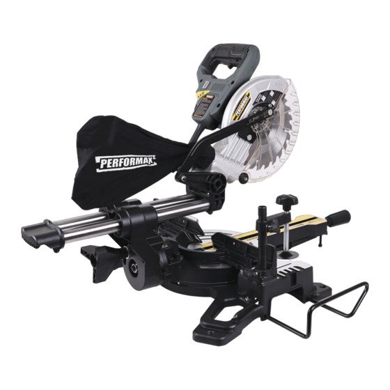
COMPOUND MITER SAW
PRODUCT SPECIFICATIONS
120 VOLTS AC, 60Hz
9.5 Amps
5000 RPM (No-Load Speed)
7-1/4" 24 tooth carbide tipped
5/8"
0, 15, 22.5, 31.6 & 45 degree
47 degree Left/ 47 degree Right
10ft
21 lbs
90° cross cut 2-3/8" x 11-1/2"
45° miter cut 2-3/8" x 7-7/8"
7-1/4 " SLIDING
Owner's Manual
45° bevel cut 1-1/2" x 11-1/2"
45° miter/bevel cut 1-1/2"" x 7-5/8"
240-3680
Advertisement

Related Manuals for Performax 240-3680


Summary of Contents for Performax 240-3680
- Page 1 7-1/4 " SLIDING COMPOUND MITER SAW 240-3680 Owner's Manual PRODUCT SPECIFICATIONS Voltage 120 VOLTS AC, 60Hz Current rating 9.5 Amps Blade Speed 5000 RPM (No-Load Speed) Blade Diameter 7-1/4" 24 tooth carbide tipped Arbor Size 5/8" Positive Miter Stops 0, 15, 22.5, 31.6 & 45 degree...
-
Page 2: Table Of Contents
TABLE OF CONTENTS IMPORTANT SAFETY INSTRUCTIONS ....... Page 3 SAFETY PRECAUTIONS FOR COMPOUND MITER SAW ..Page 4 FUNCTIONAL DESCRIPTION ........Page 5 OPERATING PROCEDURES ........Page 6 MAINTENANCE ............Page 7 PARTS LIST .............Page 11 ASSEMBLY DRAWING ..........Page 12 WARRANTY .............Page 13... -
Page 3: Important Safety Instructions
IMPORTANT SAFETY INSTRUCTIONS WARNING: When using electric tools, machines or equipment, basic safety precautions should always be followed to reduce the risk of fire, electric shock, and personal injury. Read all instructions before using this tool! Keep work area clean. Cluttered areas invite injuries. Consider work area environment. -
Page 4: Safety Precautions For Compound Miter Saw
Don't force the tool. It will do the job better and more safely at the rate for which it was intended. Use the right tool. Don't force a small tool or attachment to do the work of a larger industrial tool. -
Page 5: Functional Description
Connect your miter saw to a dust collecting device if possible. If not, use the dust bag that comes with the tool and empty it regularly. Use a saw blade suited to the cutting job and material to be cut. Always use table extensions and clamps to support the material when sawing long work pieces. -
Page 6: Operating Procedures
OPERATING PROCEDURES Caution: Be sure the saw is disconnected from its power source before making any repairs or performing maintenance! Clamping Workpiece: WARNING: For safe and accurate cuts, fix workpiece firmly into cutting position with hold-down damp, otherwise the tool and workpiece may be damaged. Mount the hold-down clamp on one side of fence. -
Page 7: Maintenance
To begin cutting, lower the cutting head. The lower blade guard opens automatically. ■ After cutting, allow the head to come back up. The guard will close automatically. ■ The saw will stop when you release the trigger switch in the handle. ■... - Page 8 Keep the vents clear of dust and debris. This will help prevent possible electrical shorts and ensure ■ proper cooling. Keep the tool housing and handle dean and free of oil and grease by using mild soap and a damp ■...
- Page 9 square. If not: 1. Use an open-end wrench to loosen the hex lock nut and then turn the hex stop bolt at the back left side of the table. 2. Turn the bolt clockwise and the 45 degrees point moves left, opening the angle. Turning it counter-clockwise moves the 45 degrees stop to the right, closing the angle.
- Page 10 4. Raise the lower blade guard and use supplied FIG.3 phillips screwdriver to loosen screw almost 7/32". (See Figure 3 ) 5. The lower blade guard can be held in the up position by the screw. Push the locating plate upward. (See Figure 4 ) screw locating...
-
Page 11: Parts List
PARTS LIST Please refer to the schematic drawing on page 12. Cross head screws Bearing sleeve Table insert (Rightt) Washer Tapping screw Socket screws Self -tapping screws Stator Hex nut Upper handle Rating label Handle cap Switch trigger assembly Motor housing Mitre handle Switch trigger Warning label... -
Page 12: Assembly Drawing
ASSEMBLY DRAWING... -
Page 13: Warranty
At its discretion, PERFORMAX agrees to have the tool or any defective part(s) repaired or replaced with the same or similar PERFORMAX product or part free of charge, within the stated warranty period, when returned by the original purchaser with original sales receipt.
Need help?
Do you have a question about the 240-3680 and is the answer not in the manual?
Questions and answers