Table of Contents
Advertisement
Quick Links
10'' SLIDING COMPOUND MITER SAW
240-3689
OPERATOR'S MANUAL
CAUTION:
To Reduce The Risk Of Injury, User Must Read And
Understand Operator's Manual. Save These Instructions For Future
Reference.
For questions / comments, technical assistance or repair parts –
Please Call Toll Free: 1-866-858-2664. (M-F 8:30am-5:00pm Est.)
Advertisement
Table of Contents

Related Manuals for Performax 240-3689


Summary of Contents for Performax 240-3689
- Page 1 10’’ SLIDING COMPOUND MITER SAW 240-3689 OPERATOR’S MANUAL CAUTION: To Reduce The Risk Of Injury, User Must Read And Understand Operator’s Manual. Save These Instructions For Future Reference. For questions / comments, technical assistance or repair parts – Please Call Toll Free: 1-866-858-2664. (M-F 8:30am-5:00pm Est.)
-
Page 2: Table Of Contents
TABLE OF CONTENTS Safety Symbols ............Page 2 Safety Instructions . -
Page 3: Safety Symbols
SAFETY SYMBOLS Some of these following symbols may be used on this tool. Please study them and learn their meaning. Proper interpretation of these symbols will allow you to operate the tool better and more safely. Symbol Designation / Explanation Name Volts Voltage... -
Page 4: Safety Instructions
SAFETY INSTRUCTIONS The purpose of safety symbols is to attract your attention to possible dangers. The safety symbols, and the explanations with them, deserve your careful attention and understanding. The symbol warnings do not, by themselves, eliminate any danger. The instructions and warnings they give are no substitutes for proper accident prevention measures. - Page 5 SAFETY INSTRUCTIONS SAVE ALL WARNINGS AND WARNING: Safety symbols in INSTRUCTIONS FOR FUTURE this Instruction Manual are used to flag REFERENCE. possible dangers. The safety symbols and their explanations require your full understanding. The safety warnings do not, The term “power tool” in the warnings refers by themselves, eliminate any danger, nor to your mains-operated (corded) power tool are they substitutes for proper accident...
- Page 6 SAFETY INSTRUCTIONS • When operating power tool be caught in moving parts. outdoors, use an extension cord • If devices are provided for the suitable for outdoor use. Use of a cord connection of dust extraction and collection facilities, ensure these are suitable for outdoor use reduces the connected and properly used.
- Page 7 SAFETY INSTRUCTIONS • Keep cutting tools sharp and clean. too close to the saw blade, there is Properly maintained cutting tools with an increased risk of injury from blade sharp cutting edges are less likely to contact. • The workpiece must be stationary bind and are easier to control.
- Page 8 SAFETY INSTRUCTIONS • Do not use the saw until the table • Always use a clamp or a fixture is clear of all tools, wood scraps, designed to properly support round etc., except for the workpiece. Small material such as rods or tubing. Rods debris or loose pieces of wood or other have a tendency to roll while being cut, objects that contact the revolving blade...
- Page 9 SAFETY INSTRUCTIONS correct direction. The teeth on the • Use only blades of the correct size and type specified for this tool to blade should point in the direction of prevent damage to the machine and/ rotation as marked on the saw. •...
- Page 10 SAFETY INSTRUCTIONS • Never leave tool running unattended. • Never lift this tool by gripping the switch handle or by the miter fence. Turn power off. Don’t leave tool until it comes to a complete stop. This may cause misalignment. Always •...
- Page 11 SAFETY INSTRUCTIONS GLOSSARY OF WOODWORKING • If the supply cord of this power tool is damaged, it must be replaced TERMS specially prepared supply cord available through the service 1. Spindle: The revolving shaft on which a organization. blade or cutting tool is mounted. •...
- Page 12 SAFETY INSTRUCTIONS 14. No-Hands Zone: The area between the − Lead from lead-based paints marked lines on the left and right side − Crystalline silica from bricks, cement, of the miter-table base. This zone is and other masonry products identified by No-Hands Zone symbols −...
-
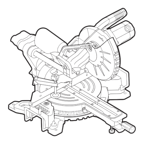
Page 13: Overview/Specifications
OVERVIEW Switch Dust Bag Lower Blade Guard Work Clamp Mounting Hole Sliding Fence Table Insert Lower Fence Extension Bar Miter Stop Miter Locking Knob Locking Lever Depth Adjustment Screw Spindle Lock Lock-down Pin Slide-Rail Lock Knob Table Bevel Scale Bevel Lock Knob Miter Scale Base Page 12... - Page 14 SPECIFICATIONS Motor 120V~, 60Hz, 15A Speed 5000 RPM (no load) Blade 10" (25.4 cm) (40-tooth) Arbor size 5/8" (15.9 mm) 3-1/2’’X12-3/8’’, miter 0°, bevel 0° 3-1/2’’X8-7/16’’, miter 45°, bevel 0° Cutting capacity 1-9/16’’X12-3/8’’, miter 0°, bevel 45° 1-9/16’’X8-7/16’’, miter 45°, bevel 45° Weight 36 lb.
-
Page 15: Assembly
ASSEMBLY CONTENTS WARNING: If any part is broken or missing, DO NOT operate the tool until the Sliding compound miter saw, miter lever, broken or missing part is replaced. Failure work clamp, dust bag, 2 extension bars, to do so could result in possible serious phillips screwdriver and instruction manual. -
Page 16: Operation
OPERATION INTENDED USE 3. Tighten the screw (1) to lock the work clamp. 4. Rotate the clamp knob clockwise to This miter saw is designed for wood cutting clamp the workpiece and rotate the applications. DO NOT use under wet conditions or in presence of flammable knob counterclockwise to release the liquids or gases. - Page 17 OPERATION INSTALL EXTENSION BARS WARNING: Always use extension (FIG.4) bars to support a long workpiece so it is level with the top surface of the main Extension bars have been provided for both table for an accurate cut and to prevent the left and the right side of the saw.
- Page 18 OPERATION MITER SCALE (FIG.6) locking knob counterclockwise. 2. Move the table while lifting up on the miter stop locking lever to align the FIG. 6a Hole indicator to the desired degree. 3. If the desired angle is one of the nine positive stops, release the miter stop locking lever, make sure the lever snaps into the detent slot, and then secure...
- Page 19 OPERATION BEVEL STOP ADJUSTMENT FIG. 7b Lower (FIG.8) Fence Hex-head This tool is carefully adjusted and aligned Bolts at the factory, but rough handling may have affected the alignment. If your tool is not aligned properly, perform the following as needed.
- Page 20 OPERATION 3. If the blade is not 90° square with the FIG. 8d table, loosen the bevel lock knob, put a 4 mm hex wrench into the hole located in the left side end of the arm holder, turn the hex screw clockwise or counterclockwise to make the blade square to the table.
- Page 21 OPERATION To lock: Place the cutting head at the FIG. 10b lowest position. Secure the position and push the lock-down pin into the locking position. Please note, if there is any cutting depth setting, the lock-down pin may not work. Release the cutting depth limitation by rotating the depth adjustment screw counterclockwise, and then lock the cutting head.
- Page 22 OPERATION CHOP CUTS (FIG.11) lower head assembly to make sure clamp clears guard and head assembly. FIG. 11 2. Loosen the slide-rail lock knob. 3. Grasp the switch handle and pull the head assembly away from the fence, until the blade clears the workpiece or to its maximum extension if blade cannot clear the workpiece.
- Page 23 OPERATION BEVEL CUT (FIG.14) FIG. 12b A bevel cut is a cut made across the grain of the workpiece with the blade at an angle to the workpiece. A straight bevel cut is made with the miter table set at the 0° position and the saw arm set at a bevel angle between 0°...
- Page 24 OPERATION COMPOUND CUTS (FIG.15) 1. Loosen the lock nut. Rotate the depth adjustment screw to the desired cutting FIG. 15 depth, and retighten the lock nut. 2. Plug the saw into an electrical socket. 3. Cut the two outside edges of the groove. 4.
- Page 25 OPERATION CUTTING WARPED MATERIAL CUTTING BASE MOULDING (FIG.17) (FIG.18) Top View Molding Lying Flat On FIG. 17a FIG. 18 Miter Table (Before Clamping) Fence Miter Saw Miter at 0°, Bevel at 45° Molding Standing Up Against Fence (Before Clamping) Fence Miter Saw Miter at 45°, Bevel at 0°...
- Page 26 OPERATION CUTTING CROWN MOULDING Crown molding has a high top rear spring angle (the section that fits flat against the (FIG.19) ceiling) of 52° and a bottom rear spring angle (the section that fits flat against the Your miter saw is ideal for cutting crown wall) of 38°.
-
Page 27: Maintenance
MAINTENACE LOWER BLADE GUARD WARNING: When servicing, use only identical replacement parts. Use of Do not use the saw without the lower blade any other parts may create a hazard or guard. cause product damage. The lower blade guard is attached to the WARNING: To avoid serious saw for your protection. - Page 28 MAINTENACE 1. First unplug the saw before inspecting FIG. 21b Outer Flange or replacing brushes. 2. Replace both carbon brushes when either has less than 1/4” (6 mm) of carbon remaining, or if the spring or wire is damaged or burned. 3.
- Page 29 MAINTENACE TRANSPORT THE SAW (FIG.23) guard. Make sure that the blade teeth are pointing downward. 3. Place the outer flange against the blade In order to conveniently carry the miter saw and on the arbor. Thread the blade bolt from place to place, a lifting handle has been onto the arbor in a counterclockwise included on the top of the saw and hand direction.
-
Page 30: Troubleshooting
TROUBLESHOOTING PROBLEM POSSIBLE CAUSE SOLUTION Brake does not 1. Motor brushes not sealed or 1. Inspect/clean/ stop blade within 10 lightly sticking. replace brushes. See seconds. MAINTENANCE section. 2. Motor brake overheated from 2. Use a recommended blade. use of defective or wrong size blade or rapid ON/OFF cycling. -
Page 31: Warranty
2-Year Limited Warranty to the original ® purchaser. If, during normal use, this PERFORMAX® power tool breaks or fails due to a defect in material or workmanship within two (2) years from the date of original... - Page 32 © 2019 Menard, Inc., Eau Claire, WI 54703 11/2019...
Need help?
Do you have a question about the 240-3689 and is the answer not in the manual?
Questions and answers