Table of Contents
Advertisement
Rated Power :
Max. Cutting Depth :
No Load Speed :
Blade Size :
Need Assistance ?
Call us on our toll free customer support line :
1-866-915-8626
• Technical questions
• Replacement parts
• Parts missing from package
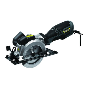
PRODUCT SPECIFICATIONS
4-1/2" Compact
Circular saw
5.8A
(90 ⁰ ) : 1-3/4"
(45 ⁰ ) : 1-1/8"
3500/min(no load)
4-1/2"×3/8"×24T
241-0944
Owner's Manual
Advertisement
Table of Contents

Related Manuals for Performax 241-0944


Summary of Contents for Performax 241-0944
- Page 1 4-1/2" Compact Circular saw 241-0944 Owner's Manual PRODUCT SPECIFICATIONS Rated Power : 5.8A (90 ⁰ ) : 1-3/4" Max. Cutting Depth : (45 ⁰ ) : 1-1/8" No Load Speed : 3500/min(no load) Blade Size : 4-1/2"×3/8"×24T Need Assistance ?
-
Page 2: Table Of Contents
TABLE OF CONTENTS General Safety Rules..................Page 2 Specific Safety Rules................... Page 4 Symbols....................... Page 6 Electrical...................... Page 7 Features....................... Page 8 Overview Components................. Page 9 Assembly...................... Page 9 Operation..................... Page 12 Maintenance....................Page 14 Parts list....................... Page 15 Exploded view....................Page 17 Warranty....................... - Page 3 2) Electrical safety a) Power tool plugs must match the outlet. Never modify the plug in any way. Do not use any adapter plugs with earthed (grounded) power tools. Unmodified plugs and matching outlets will reduce risk of electric shock. b) Avoid body contact with earthed or grounded surfaces, such as pipes, radiators, ranges and refrig- erators.
- Page 4 e) Maintain power tools. Check for misalignment or binding of moving parts, breakage of parts and any other condition that may affect the power tool’s operation. If damaged, have the power tool repaired before use. Many accidents are caused by poorly maintained power tools. f) Keep cutting tools sharp and clean.
-
Page 5: Specific Safety Rules
SPECIFIC SAFETY RULES WARNING Keep hands away from the cutting area and blade. NEVER place your hands behind the saw blade since kickback could cause the saw to jump backwards over your hand. Keep your body positioned to either side of the saw blade. SAVE THESE INSTRUCTIONS - Check the lower guard for proper closing before each use. - Page 6 KICKBACK Kickback is a sudden reaction to a pinched, bound or misaligned saw blade, causing an uncontrolled saw to lift up and out of the workpiece toward the operator. - When a blade is pinched or bound tightly by the Nerf closing down, the blade stalls and the motor reaction may drive the unit back toward the operator rapidly.
-
Page 7: Symbols
Safety instruction for saws - Check lower guard before each use. Do not operate the saw if the lower guard does not move freely and close instantly. Never clamp or tie the lower guard into the open position. If saw is accidentally dropped, lower guard may be bent. -
Page 8: Electrical
Symbol Description DESIGNATION/EXPLANATION Safety Alert Indicates a potential personal injury hazard. Volts Voltage Amperes Current Hertz Frequency (cycles per second) Minutes Time Alternating Current Type of current No Load Speed Rotational speed, at no load Class II Tool Double-insulated construction .../min Per Minute Revolutions, strokes, surface speed, orbits etc., per... -
Page 9: Electric Connection
ELECTRIC CONNECTION This tool has a precision-built electric motor. It should be connected to a power supply that is 120 volts, 60 Hz, AC only (normal household current). Do not operate this tool on direct current (DC). A substantial voltage drop will cause a loss of power and the motor will overheat. If your tool does not operate when plugged into an outlet, double-check the power supply. -
Page 10: Overview Components
OVERVIEW COMPONENTS Fig. 1 A - Saw blade Lower guard B - Switch Base plate C - Lock button Storage for hexagon key D - Upper guard Spindle lock E - Angle locking lever Depth locking lever F - Parallel guide lock screw Depth scale Parallel guide Dust outlet... -
Page 11: Switching On And Off
- Make sure that the new saw blade is well centered at the inner flange when mounting the blade. - Make sure the direction of rotation from the blade is the same as the rotation direction of the tool, refer to the direction arrow at the tool and the direction arrow at the saw blade - Reinstall the outer flange, washer and tighten the blade clamp screw. -
Page 12: Depth Adjustment
Depth Adjustment - Before any adjustment, ensure the power plug is removed from the socket. - Loosen the depth adjustment screw using the depth locking lever (O). - Hold the base plate flat against the body of the work piece and lift the body of the saw until the blade is at the correct depth. -
Page 13: Operation
OPERATION General Cut - Mark a cutting line on the workpiece (U). - Rest the front part of the base plate(L) flat on the workpiece surface with the blade not making any contact with the workpiece. - Switch on the tool and allow it to reach its full speed. - Align the saw blade with the cutting line on the workpiece, gently push the saw forward. -
Page 14: Maintenance
Pocket Cut - Disconnect the plug from the power supply before making any adjustments. - Set the depth adjustment based on the thickness of the required cut. - Raise the lower guard by using the lower guide lever. - With the blade barely above the material to be cut, start the saw and allow the blade to attain full speed. -
Page 15: Parts List
CAUTION Certain cleaning agents and solvents may damage plastic parts. Some of these are: gasoline, carbon tetrachloride, chlorinated cleaning solvents, ammonia and household detergents that contain ammonia. WARNING If any of the following events occur during normal operation, the power supply should be shut off at once and tool thoroughly inspected by a qualified person and repaired if necessary: - The rotating parts get stuck or speed drops abnormally low. - Page 16 Big gear Stator Circlip for shaft D9 Deep groove ball bearing 608-2Z Circlip for shaft D8 Rotor Pinion Socket terminal 2.8X0.8 Separation sleeve Self-tapping screw ST2.9X10 Circlip for hole D20 Lower carbon brush holder Deep groove ball bearing 699 Carbon brush Pipe joint C Deep groove ball bearing 606.2Z Bellows...
- Page 17 SCHEMATIC DRAWING...
-
Page 18: Warranty
At its discretion, PERFORMAX agrees to have the tool or any defective part(s) repaired or replaced with the same or similar PERFORMAX product or part free of charge, within the stated warranty period, when returned by the original purchaser with original sales receipt.
Need help?
Do you have a question about the 241-0944 and is the answer not in the manual?
Questions and answers