
Subscribe to Our Youtube Channel
Related Manuals for Performax 240-3600


Summary of Contents for Performax 240-3600
- Page 1 10” Table Saw with Stand 240-3600 OPERATOR’S MANUAL CAUTION: To Reduce The Risk Of Injury, User Must Read And Understand Operator’s Manual. Save These Instructions For Future Reference. Page 1...
- Page 2 TAbLE OF CONTENTS Safety Symbols . . . . . . . . . . . . . . . . . . . . . . . . . . . . . . . . . . . . . . . . . . . . . . . . . . . . . . . . . Page 2 Safety Instructions .
-
Page 3: Safety Symbols
SAFETy SyMbOLS Some of these following symbols may be used on this tool . Please study them and learn their meaning . Proper interpretation of these symbols will allow you to operate the tool better and safer . Symbol Designation / Explanation Name Volts Voltage... -
Page 4: Safety Instructions
SAFETy INSTRUCTIONS The purpose of safety symbols is to attract your attention to possible dangers . The safety symbols and the explanations with them deserve your careful attention and understanding . The symbol warnings do not, by themselves, eliminate any danger . The instructions and warnings they give are no substitutes for proper accident prevention measures . -
Page 5: General Safety Rules
SAFETy INSTRUCTIONS RULES FOR SAFE OPERATION 9) Use the proper extension cord. Make sure that your extension cord is in good KNOW THE TOOL condition . When using an extension cord, To reduce the risk of injury, user must read be sure to use one that is heavy enough instruction manual . -
Page 6: Specific Safety Rules
SAFETy INSTRUCTIONS 19) Check damaged parts. Before further 6) Always use a push stick for ripping narrow stock. A push stick is a device that use of the tool, any guard or other part that is damaged should be carefully checked to is used to push a workpiece through the determine whether it will operate properly blade instead of using your hands . - Page 7 SAFETy INSTRUCTIONS D) Not releasing the work before it is 28) Use a push-stick when required. 29) Disconnect the tool and be sure the pushed all the way past the saw blade blade has come to a complete stop before using a push stick .
- Page 8 SAFETy INSTRUCTIONS ELECTRICAL SAFETy (FIG. 1) Repair or replace a damaged or worn cord immediately. Permanently connected tools: This tool FIG. 1 should be connected to a grounded metal permanent wiring system or to a system that has an equipment-grounding conductor . GUIDELINES FOR EXTENSION CORDS Use a proper extension cord.
-
Page 9: Glossary Of Terms
SAFETy INSTRUCTIONS Recommended size of extension cords Table 1 Total length of the Amperage rating extension cord of the tool (120 V circuit only) 25’ 50’ 100’ 150’ More than Not more than Minimum Gauge for the extension cord (AWG) Not recommended 8 . -
Page 10: Assembly
SAFETy INSTRUCTIONS 17 . bevel scale: The easy-to-read scale on 27 . Sliding extension table: Located on the the front of the table saw cabinet shows the right side of the saw table, this extension exact blade angle . table gives the operator additional support 18 . -
Page 11: Product View
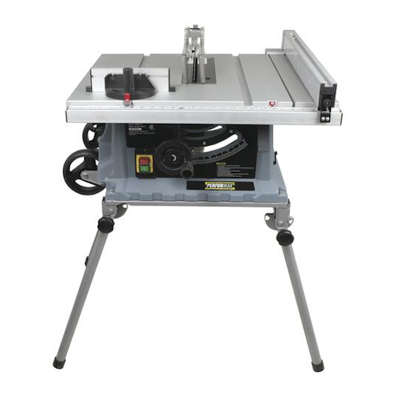
OVERVIEW FIG. 2 Anti-kickback pawls Blade guard Spreader/ Riving knife Rip fence Miter gauge Cord storage Push stick Fence locking lever Cord Stand Bevel locking lever Bevel scale indicator Bevel scale Height/bevel adjusting ON/OFF switch hand wheel assembly SPECIFICATIONS Rating 120 V, 60 Hz Motor No load speed... - Page 12 ASSEMbLy CONTENTS WARNING: Do not attempt to modify this tool or create accessories not Blade guard . . . . . . . . . . . . . . . . . . . . 1 pc recommended for use with this tool.
-
Page 13: Mounting The Saw
ASSEMbLy 4 . Place a washer onto each of the short FIG. 3a carriage bolts . Insert the short carriage Push bolts up through the holes in the supports . Place a washer and a nut on the threads of each bolt . Tighten all nuts securely . -
Page 14: Operation
ASSEMbLy SPREADER/RIVING KNIFE WARNING: When you position the POSITIONS (FIG. 5-6) table saw against the stand, make sure the two outside legs which are inserted into the limit-support are below the back FIG. 5 of the table saw as shown in fig. 3b. STORING ACCESSORIES The table saw has two convenient storage areas specifically designed for accessories... -
Page 15: Checking Saw Blade Installation
ASSEMbLy CHECKING SAW bLADE To place the spreader/riving knife in the spreader position (“up” position) for all INSTALLATION (FIG. 7) through-cutting: 1 . Unplug the saw . 2 . Remove the throat plate by placing your FIG. 7 index finger in the hole and lifting the front end, then pull the throat plate out toward the front of the saw (Fig . -
Page 16: Blade Guard Assembly
ASSEMbLy To loosen the blade: FIG. 8b 1 . Using the open-end wrench, place the flat open-end on the flat surfaces on the arbor shaft . 2 . Put the closed-end wrench onto the hex nut . Holding both wrenches firmly, pull the closed-end wrench toward the front of the machine . -
Page 17: Checking/Aligning Spreader/Riving Knife/Blade
ASSEMbLy 1 . Unplug the saw . FIG. 9b 2 . Raise the saw blade as high as it will go by turning the Height/bevel-adjusting hand wheel clockwise . 3 . Remove the anti-kickback pawls, and place a framing square or straight edge against both the saw blade and the spreader . -
Page 18: Changing The Blade
ASSEMbLy CHANGING THE bLADE 1 . Unplug the saw . 2 . Loosen the bevel control by pulling DEPTH (FIG. 12) the bevel-locking lever out . 3 . To adjust the bevel angle, push the wheel FIG. 12 in toward the saw, and then turn it . Turning the wheel counter-clockwise increases the angle of the blade, bringing it closer to 45º;... -
Page 19: Adjusting The Bevel
ASSEMbLy CHECKING THE ALIGNMENT 6 . Set the 45° stop the same way . The set screw for the 45° stop is located under OF THE RIP FENCE TO the right miter guide slot . THE bLADE (FIG. 16a) FIG. 14b FIG. -
Page 20: Using The Rip Fence
ASSEMbLy SETTING THE RIP FENCE SCALE 1 . Unplug the saw . 2 . Place the front lip of the rip fence INDICATOR TO THE on the front of the saw table and push bLADE (FIG. 16b) it slightly toward the back of the unit . 3 . -
Page 21: Using Sliding Extension Table
ASSEMbLy ALIGNING THE bLADE TO THE 3 . Retighten the locking knob and push the stop pin in . MITER GAUGE GROOVE To check the angle indicator: (FIG. 20-21) Loosen the locking knob and place a 90º square against the miter gauge rod and the miter gauge base to verify that the angle FIG. - Page 22 ASSEMbLy 1 . Unplug the saw . If the distances are different: 2 . Turn the height-adjusting handle to 1 . Loosen adjusting bolts (1) and (2) using raise the blade all the way . the included 15/64” (6 mm) hex key . 3 .
-
Page 23: Table Saw
OPERATION bASIC OPERATION OF THE WARNING: Do not allow familiarity TAbLE SAW with a tool to make you careless. Remember that a fraction of a second of carelessness is sufficient to cause serious The 3-pronged plug must be plugged into injury. -
Page 24: Avoiding Kickback
OPERATION AVOIDING KICKbACK Push sticks are devices used for safely pushing a workpiece through the blade instead of using your hands . They can be 1 . Always use the correct blade depth made from scrap wood in various sizes setting . - Page 25 OPERATION FEATHERbOARD 4 . Mark the board from the point at 6” (15 cm), 8” (20 cm), 10” (25 cm), and 12” (30 cm) . Drill a 3/8” (9 .5 mm) hole at the A featherboard is a device used to help 8”...
- Page 26 OPERATION SWITCH ASSEMbLy (FIG. 27) 5 . Attach a C-clamp (available separately) to secure the featherboard to the edge of the saw table . FIG. 27 Switch off WARNING: Do not locate the featherboard to the rear of the workpiece. If positioned improperly, kickback can result from the featherboard pinching the workpiece and binding the blade in the...
-
Page 27: Overload Protection
OPERATION 4 . Never store blades stacked on top of WARNING: ALWAyS make sure one another . Place material such as that your workpiece is not in contact with cardboard between them to keep the the blade before operating the switch to blades from coming into contact with start the tool. - Page 28 OPERATION 4 . Hold the workpiece flat on the table and WARNING: Never touch the “free against the fence . Keep the workpiece end” of the workpiece or a “free piece” approximately 1” (25 mm) away from the that is cut off while the power is ON and/ blade .
- Page 29 OPERATION bEVEL RIPPING (FIG. 29) FIG. 30 FIG. 29 ” 2 - 6 When the width of rip is narrower than 2” (5 cm), the push stick cannot be used because the guard will interfere . USE the WARNING: This operation is the auxiliary fence and push block .
- Page 30 OPERATION CROSSCUTTING (FIG. 34) Feed the workpiece by hand until the end is approximately 1” (25 mm) from the front edge of the table . Continue to feed using the push block on top of auxiliary fence FIG. 34 until the cut is complete (Fig . 32) . FIG.
- Page 31 OPERATION bEVEL CROSSCUTTING (FIG. 35) WARNING: Use caution when starting the cut to prevent binding of the guard against the workpiece, resulting in FIG. 35 damage to saw and possible injury. WARNING: When using a block as a cut-off gauge, the block must be at least 3/4”...
-
Page 32: Compound Mitering
OPERATION MITERING (FIG. 36) COMPOUND MITERING This is a combination of bevel crosscutting FIG. 36 and mitering . Follow the instructions for both bevel crosscutting and mitering . MAKING A NON-THROUGH CUT (FIG. 37) FIG. 37 Inner flange Arbor shaft Outer Bushing flange... - Page 33 OPERATION 7 . Allow the blade to reach full speed 1 . Unplug the saw . before moving the workpiece into the 2 . Remove the blade guard, anti-kickback blade . pawls, and throat plate . 8 . After the cut is made, turn the saw off . 3 .
-
Page 34: Dust Collection
OPERATION DUST COLLECTION Your table saw is equipped with a dust extraction port . For best results, connect a vacuum to the port at the rear of the saw . If the saw is operated without a vacuum attached, some of the dust will be blown out the dust collection port . -
Page 35: Troubleshooting
TROUbLESHOOTING PRObLEM CAUSE SOLUTION 1 . Excess vibration . 1 . Blade is out of balance . 1 . Replace blade . 2 . Blade is damaged . 2 . Replace blade . 3 . Saw is not mounted securely . 3 . - Page 36 TROUbLESHOOTING PRObLEM CAUSE SOLUTION 8 . Saw does not start . 1 . Power cord is not plugged in . 1 . Plug in Power cord . 2 . In-house circuit fuse is blown . 2 . Replace the fuse . 3 .
- Page 37 NOTES Page 36...
- Page 38 NOTES Page 37...
-
Page 39: Day Money Back Guarantee
This PERFORMAX® brand power tool carries a 2-Year Limited Warranty to the original purchaser . If, during normal use, this PERFORMAX® power tool breaks or fails due to a defect in material or workmanship within two (2) years from the date of original purchase, simply bring this tool with the original sales receipt back to your nearest MENARDS®... - Page 40 © 2012 Menard, Inc ., Eau Claire, WI 54703 01/2012 Page 40...
Need help?
Do you have a question about the 240-3600 and is the answer not in the manual?
Questions and answers
I am needing a new rip fence. Where can it be purchased?