
Related Manuals for Shimadzu SALD-7101


Summary of Contents for Shimadzu SALD-7101
- Page 1 347-06772A Nano Particle Size Analyzer SALD-7101 Service Manual Read this instruction manual thoroughly before you use the instrument. Keep this instruction manual for future reference.
- Page 3 Tools list for repairing SALD-7101 When you repair the SALD-7101, prepare beforehand the Tools and Jigs that are shown below. Tools Screw driver for cross recessed head screws : #0 Screw driver for cross recessed head screws : #2 Screw driver : 2.6mm Screw driver : 6mm Hexagon socket screw key : 1.5mm...
-
Page 5: Table Of Contents
Contents 1. General Description ....................1 2. Measuring Unit ......................2 2.1 Adjustments of Optical System................2 2.1.1 Precautions......................2 2.1.2 Guidance for adjustments ................. 5 2.1.3 Adjustment Procedure..................6 2.2 Troubleshooting for Measuring unit..............13 3. Sampler (SALD-MS71)..................... 18 3.1 Procedures for Disassembling and Reassembling the Sampler...... -
Page 7: General Description
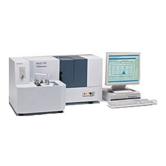
1. General Description As shown in Fig. 1.1, the SALD-7101 consists of a measuring unit, a sampler (SALD-MS71), and a personal computer. The measuring unit and the sampler are completely independent except for the circulation of sample solution. Each of these two units has its own CPU for communications and control, which is controlled via the RS-232C port by the personal computer. -
Page 8: Measuring Unit
2. Measuring Unit The measuring unit consists of an optical system and main printed circuit boards including an amplifier and an A/D converter. This section covers the adjustment procedure for the optical system and the troubleshooting of the entire measuring unit. 2.1 Adjustments of Optical System 2.1.1 Precautions The safety precautions required for adjusting the optical system are given below. - Page 9 Table 2.1 Use jig list Jig Name Reference (Section No.) Laser power meter Adjustments in Section 2.1.3(1) and (5) Short-circuit plug (346-60842) Adjustments in Section 2.1.3(1) to (6) Target for the cell position (347-60699) Adjustments in Section 2.1.3(3) Centering target (make of blank paper) Adjustments in Section 3.1.2(2) Latex 0.050 m Adjustments in Section 2.1.3(6)
- Page 10 Fig 2.1 Short-circuit plug Fig 2.2 Target for the cell position White paper Circle of 3 mm in diameter Fig 2.3 Beam diameter target (Draw in the white paper.)
-
Page 11: Guidance For Adjustments
2.1.2 Guidance for adjustments The adjustment procedure described in Paragraph 2.1.3 is used during manufacture. All of these steps are not required to be taken during repair, but only the necessary steps should be carried out. Situation Adjustment step (1) Adjustment of unloaded Exchange of a laser diode output of laser diode (2) Adjustment of parallel light,... -
Page 12: Adjustment Procedure
2.1.3 Adjustment Procedure First remove the sliding door case located at the center of the measuring unit. Because a right case is an opening and shutting type door, open it to right side. Afterwards, remove three screws of (A) shown in Fig 2.5. Place the case on the rear of the measuring unit and then disconnect the cable connected to the rear of the case via the connector. - Page 13 Assembly (P/N) Repair Parts Name Repair P/N LENS, R (16,27)-1 347-60925 LENS, R (16,17)-2 347-60926 LENS, R (16,25N)-3 347-60927 Lens A ASSY LENS, R (16,15N)-4 347-60928 (347-60946) Slit, FAI 7 347-60944 Solenoid ASSY 347-60663 LD ASSY, 375 347-60937 Slide rail, AR-200 037-38205-02 Cell holder ASSY Plunger, FP-8 (For positioning)
- Page 14 Since the above adjustment is made visually, take care that any human eye never be directly exposed to the beam. Laser radiation Exposures to the eyes or the skins by the beam are dangerous. Do not see or touch. Maximum output: 10mW, Wavelength: 375nm, Class 3B laser product (1) Adjustment of unloaded output of laser diode 1) Fully turn the VR1 on the laser driver assembly (346-63352, see Fig.
- Page 15 Fig. 2.7 Laser driver assembly (P/N: 346-63352) (2) Adjustment of optical beam, and positional adjustment of slit 1) Evoke the Wing-1 software of personal computer, then turn the [Laser ON]. 2) Remove the slit attached in the exit of the light source of "Lens A ASSY". 3) Please move "LDASSY, 375"...
- Page 16 Laser Draiver ASSY LDASSY,375 LENS,R(16,27)-1 LENS,R(16,17)-2 LENS,R(16,25N)-3 Slit, FAI 7 LENS,R(16,15N)-4 Slit Solenoid ASSY Fig. 2.8 Light source (3) Centering of laser beam in the cell position on X- and Y-axes 1) Mount the cell holder assembly without the cell and insert the target (Fig 2.2) into the position for the cell.
- Page 17 Take care not to increase the output excessively because the laser diode otherwise would be damaged. (5) Adjustment of sensitivities of side and rear sensors Using latex A: Never use city water, which would immediately change the quality of latex. B: Never use even such latex as diffused in de-ionized water if it has stood for 30 minutes.
- Page 18 8) Inject latex of 0.050 m dispersed. 9) Select the [Measurement] to start the measurement. 10) When the measured value is shown, Select the [Cancel], select the [Light Intensity Distribution Data], and then display the numeric data of optical intensity. 11) Total the value 7 to 11 for "Wing"...
-
Page 19: Troubleshooting For Measuring Unit
2.2 Troubleshooting for Measuring unit (1) Communication with the personal computer fails Communication with the personal computer fails. You fail to proceed to the next step from waiting for communication Change the RS-232C cable. Check +5V. (Refer to Fig.4.4) If this voltage is not detected, a failure in the power circuit board is suspected. - Page 20 (2) The light intensity data are abnormally large The light intensity data are abnormally large. Use the "Diag & Adjust" among the the Wing-1 to turn the laser off. The CPU circuit board is in failure. The data arfe still large. The target value is ->...
- Page 21 (3) The light intensity data are unstable The light intensity data are unstable. Remove the cell and then the "Diag & Adjust" to observe the light intensity value. The CPU circuit board or the All the data are always power circuit board is in failure. unstable.
- Page 22 (4) No laser beam comes out No laser beam comes out. The values of D1 to D4 do not increase by using the "Diag & Adjust". Use the "Diag & Adjust" to turn the laser on/off. The electric current value of the laser (in the LC field) changes.
- Page 23 (5) There is an abnormal peak or omission in the light intensity data There is an abnormal peak or omission in the light intensity data ("Raw Signal"). If there is an abnormal peak,the The light intensity data change cell is not clean enough. when the cell is removed.
-
Page 24: Sampler (Sald-Ms71)
3. Sampler (SALD-MS71) The procedures for disassembling, reassembling, replacing, repairing, and adjusting the components in the mechanical system of the sampler are described bellow. Those for the electric system will be discussed starting in Section 4. 3.1 Procedures for Disassembling and Reassembling the Sampler 3.1.1 Disassembly Fig.3.1 is a diagram showing the procedure for disassembling the sampler. - Page 25 Table 3.1 Repair parts list (1/2) Disassembling item Repair part name Agitation bath 347-60337 Agitation bath Agitation bath retaining screw 347-60338 Agitation bath seal 347-60340 Lever, level sensor 347-60323 Counter weight 347-60328 Parallel, level sensor 347-60324 Parallel pin, 2 × 25 026-11037-02 Socket, float shaft 347-60325...
- Page 26 Table 3.1 Repair parts list (2/2) Disassembling item Repair part name Valve ASSY 321-42694-03 Diaphragm 366-60771-10 Spacer 346-60765 Bearing, linear LMS3F 031-06702-02 Spring 034-01035-02 Washer 3 023-66130-01 E ring 026-66202 Disassembling the drain valve and Seal, drain 347-60348 drain drive valve Shaft support top 347-60347 Shaft support bottom...
- Page 27 (1) Removing the case (see Fig. 3.2) Remove seven screws of (A) shown in Fig. 3.2. Afterwards, remove a front case. Agitation bath is installed in agitation bath base including table, motor, and fitting. It can remove three (front: two screws, back: one screw) screws in agitation bath base. Next, remove eleven (center of the bottom at the left side: one screw, sampler base: two screws, back: eight screws) screws that are the fixation of the control case.
- Page 28 (About removing this part, follow content that has been described in detail to the Operation Manual "Hardware Section" of SALD-7101.) (3) Disassembling the pump head (see Fig. 3.3 and Fig. 3.4) As shown in Fig.
- Page 29 (4) Removing the table (see Fig. 3.4) Remove four screws on the upper part of the agitation bath table, and remove the table. At this time, nipple is joined to puax tube. When you pull out the puax tube, there are case of leak from joint in a nipple and a puax tube.
- Page 30 (5) Disassembling the motor (see Fig. 3.5) Remove four screws from the bottom, and remove the motor part. Gear 80-25 Setscrew Motor Base, sampler motor Fig. 3.5 Disassembling the motor...
- Page 31 (6) Disassembling SUS agitation bath (see Fig. 3.6) Remove the agitation bath, the pump head and the agitation bath table, and remove the SUS agitation bath. Remove three retaining screws of the lower part on device for remove SUS agitation bath. Remove “Prop, agitation bath”...
- Page 32 (7) Disassembling the drain valve and the drain valve actuator (see Fig. 3.7 and Fig. 3.8) Remove the E-ring attached to the valve shaft, and the remove the spring. When doing this, take care not to bend the valve shaft, which is so thin that it is liable to be bent.
- Page 33 (8) Removing the water supply pump Remove two tubes connected to the pump, and then remove the pump. (9) Disassembling the piping components (see Fig. 3.9) Disconnect the tubes as shown in Fig.3.9. Fig.3.9 Piping diagram...
-
Page 34: Reassembly
3.1.2 Reassembly The reassembling procedure is basically the reversed disassembling procedure. This paragraph describes only the points that require further information and adjustments. (1) Reassembling the drain valve (see Fig. 3.7) If the valve shaft is bent, a leak may be occurred. Make sure that the valve shaft is not bent before reassembling. -
Page 35: Troubleshooting
3.2 Troubleshooting The parenthesized numbers are the step numbers used for the disassembling procedure described in paragraph 3.1, showing the extent of disassembling. (1) Liquid leaks Liquid leaks Check the leak point (1) Replace Polytetrafluoroethylene seal. SUS agitation bath space (6) Uniformly tighten screws Seal material, Seal/tighten the nipples, Drain valve (7) - Page 36 (2) Liquid level in tank gradually decreases (Liquid gradually leaks from drain hole) Liquid level in tank gradually decreases (2) Over flow Agitation bath is not tighten Tighten agitation bath retaining screw Agitation bath seal is bad Replace the agitation bath seal There is foreign matter in Drain valve clearance between valve and...
- Page 37 (4) Pump does not rotate Pump does not rotates (1) Impeller contacts with valve (3) Adjust impeller height Pulley or belt fault (3) Rectify the fault, or replace pulley or belt Motor does not rotates (5) Check/replace fuse (see section for electric system) Motor fault (5) Replace motor Gear is damaged (4)(5)
- Page 38 (6) Ultrasonic oscillator does not work Ultrasonic oscillator does not work (1) Check it for contact failure and wetting. Connection wiring or connector is abnormal Rectify it if they are found. Check/replace fuse Electrical fault other than those in oscillator (see section for electric system) Oscillators or piezoelectric transducer is Replace both of these two components together...
- Page 39 (8) Clean water does not come Clean water does not come (1) Check for clogging Eliminate clogging Level sensor is abnormal See section for "e" (3) Water supply pump does Check/replace fuse not work (8) See section for electric system Pump is abnormal Check/replace pump Check the clean-water source, the fuse, the piping, and the pump in this order.
-
Page 40: Electric System
4. Electric System 4.1 Overview Fig 4.1 and Fig 4.2 show the wiring of the electric system. The main printed circuit boards, transformer, and some other components for the measuring unit (Fig 4.1) are located in the chassis below the optical system of the measuring unit. The remaining electric components are only the laser driver on the optical bench, the preamplifier circuit boards in the cell holder for the side and rear scattered light sensors, the solenoid for the shutter, and two microswitches located on the sliding door. - Page 41 Fig 4.1 Wiring of electric system for SALD-7101 (measuring unit)
- Page 42 Fig 4.2 Wiring of electric system for SALD-7101 (sampler)
- Page 43 Fig 4.3 Drawing the controller for the measuring unit The printed circuit boards and their functions are described bellow: (1) Measuring unit Board Name Function CPU circuit board Communication via RS-232C port, AD conversion, and external input/output AMP circuit board Amplification of output from photosensor and multiplexing of signals to A/D converter Power circuit board...
-
Page 44: Adjustments For Electric System
A/D converter. Make the following adjustment by using the "Diag & Adjust" which is one of the standard functions of the SALD-7101. Select the [Diag & Adjust] and select the [Laser OFF] to turn the laser off. Adjust the displayed average to 125 ±... - Page 45 Fig 4.5 CPU circuit board (Measuring unit P/N: 346-62678, Sampler P/N: 346-62942)
-
Page 46: Changing The Power Voltage
4.3 Changing the power voltage When the power-supply voltage is changed from UL standard (100V/115V) to European standard (230V), it is necessary to do the wiring change and the fuse exchange to the measuring unit and the sampler. (1) Change of the wiring (refer to Fig 4.6 and Fig 4.7) Concerning the wiring in the measuring unit, change only the specified lead wire connected to the TS-1 terminal bracket in the chassis as shown in Fig 4.6. - Page 47 FROM KEY SWITCH FROM TRANSFORMER 100V115V 230V ① ② ③ ④ ⑤ ⑥ ⑦ ⑧ ⑨ Change this brown wire FROM LINE FROM FUSE FILTER HOLDER Fig 4.6 Change the power voltage for measuring unit FROM SWITCH FROM TRANSFORMER 100V115V 230V ①...
-
Page 48: Checking Each Circuit Board
4.4 Checking Each Circuit Board (1) Measuring unit CPU circuit board: Most of the checks can be made using the "Diag & Adjust" which is one of the standard functions of the personal computer. However, the I/O line to the outside cannot be checked. Check this circuit board together with the following AMP circuit board. - Page 49 (2) Sampler CPU circuit board: This circuit board is the same as the CPU circuit board in the measuring unit, except for its ROM. However, it does not include the A/D converter. This circuit board cannot be checked independently, so should be checked together with the following switching circuit board.
-
Page 50: Diagrams Of Printed Circuit Boards
4.5 Diagrams of Printed Circuit Boards F1 = 1.6A for pump motor F2 = 1.0A for ultrasonic F3 = 2.0A for water supply pump F4 = 1.0A for drain valve Fig 4.8 Switching circuit board (P/N: 346-62676) - Page 51 Fig 4.9 Preamplifier circuit board for sensor (P/N: 346-63450) Fig 4.10 AMP circuit board (P/N: 346-63451)
Need help?
Do you have a question about the SALD-7101 and is the answer not in the manual?
Questions and answers