
Subscribe to Our Youtube Channel
Related Manuals for Veratron VL FLEX Series


Summary of Contents for Veratron VL FLEX Series
- Page 1 VL FLEX 52MM SERIES VL FLEX 52 NMEA 2000 USER MANUAL rev. AD B000882...
- Page 2 LANGUAGE PAGE ENGLISH DEUTSCH ITALIANO FRANÇAIS ESPAÑOL B000882...
- Page 3 VL FLEX 52MM SERIES VL FLEX 52 NMEA 2000 USER MANUAL rev. AD B000882...
-
Page 4: Table Of Contents
CONTENT CONTENT Content ......................2 Introduction ....................3 Package Contents ..................... 3 The All-in-One Device ..................... 3 Contactless Configuration ..................3 Architecture ........................3 Safety Information ..................4 Safety During Installation ..................4 Safety After Installation ................... 5 Electrical Connection ....................5 Installation .................... -
Page 5: Introduction
INTRODUCTION INTRODUCTION PACKAGE CONTENTS Part Number Description B00043501 or 1x VL Flex 52 – NMEA 2000 (black B00111301 or white) A2C5205947101 1x 52 mm Spinlock nut A2C9582260001 1x Wiring harness B000100 1x Safety instructions THE ALL-IN-ONE DEVICE The VL Flex 52 can be easily configured as the display device you need thanks to its 1.44" TFT display, readable even in strong sunlight, embedded in a standard 52 mm diameter housing. -
Page 6: Safety Information
• Use our product only as intended. Use of the • Modifications or manipulations to veratron product for reasons other than its intended use products can affect safety. Consequently, you may lead to personal injury, property damage may not modify or manipulate the product! •... -
Page 7: Safety After Installation
SAFETY INFORMATION • Note the necessary clearance behind the drill conventional test lamps can cause damage to control units or other electronic systems. hole or port at the installation location. • The electrical indicator outputs and cables Required mounting depth: 65 mm. •... -
Page 8: Installation
INSTALLATION INSTALLATION Before beginning, disconnect the negative terminal on the battery, otherwise you risk a short circuit. If the vehicle is supplied by auxiliary batteries, you must also disconnect the negative terminals on these batteries! Short circuits can cause fires, battery explosions and damage to other electronic systems. Please note that when you disconnect the battery, all volatile electronic memories lose their input values and must be reprogrammed. -
Page 9: Mounting With Spinlock Nut
INSTALLATION MOUNTING WITH SPINLOCK NUT Conventional mounting. (Device is inserted into the hole from the front). The panel thickness can be in the range of 0.5 to 20 mm. The hole must have a diameter of 53 mm [B]. • Do not drill holes and installation openings in load-bearing or stabilizing struts or spars! •... -
Page 10: Flush Mounting
INSTALLATION FLUSH MOUNTING The recommended panel thickness is 1.5 to 3mm. The hole must have a diameter of 48.1mm [A]. Make sure that the installation location is level and has no sharp edges. • Do not drill holes and installation openings in load-bearing or stabilizing struts or spars! •... -
Page 11: Connections
CONNECTIONS CONNECTIONS PINOUT Pin no. Cable color Description Term. 15 - Battery 12 / 24 V Black Term. 31 - Ground Green / Red Signal - Frequency sensor Yellow / Red Signal - Resistive sensor Blue / White LIN bus Red / White Illumination day/night NMEA 2000 High (on M12... -
Page 12: Nmea 2000® Pinout
CONNECTIONS NMEA 2000® PINOUT Pin no. Description NET-H (CAN High) Micro-C M12 5-pin connector NET-L (CAN Low) Male, Cable View CONNECTION TO THE NMEA 2000® NETWORK Once mounting is complete, the device can be connected to the NMEA 2000® network via the designated socket on the cabling. Ensure to tighten the M12 connector by screwing it onto its counterpart, so to preserve water tightness. -
Page 13: Frequency Input Connection
CONNECTIONS FREQUENCY INPUT CONNECTION Designations within the connection diagram: 15 - Term. 15 - switched positive 12/24 V (ignition) 31 - Term. 31 - Mass F1 - Fuse 3A (not included) S1 - Illumination switch day/night (not included) RESISTIVE SENSOR CONNECTION Designations within the connection diagram: 15 - Term. -
Page 14: Configuration
CONFIGURATION CONFIGURATION VL FLEX CONFIGURATOR APP To configure the VL Flex, some parameters must be configured, e.g., the display type, the connected sensor and its calibration or the alarm threshold. This is possible via the smartphone app "VL Flex Configurator", which can be downloaded free of charge from the stores of both - Android and iOS devices. -
Page 15: Selecting Data To Display
(e.g.: Tank1/Tank2 …). Configuration: The sensor’s calibration must be entered in the table. For Veratron sensors the curves are predefined and can be imported to the table by selecting the according calibration from the dropdown menu "Characteristics". -
Page 16: Brightness And Clock
CONFIGURATION Sensor: Selection of the exact type of Intelligent Battery Sensor. Battery Type: Selection of the fitting battery type. (Gel, AGM or Flooded) Capacity: Type in the capacity of the battery. The number can be found written on the battery. On a battery pack, add up these numbers of the different batteries. - Page 17 CONFIGURATION Resistive Frequency Alarm Display type Unit Calibrations Sensor Sensor available Speed Over Ground km/h 129026 Course Over Ground 129026 Depth (below) 128267 0 - 90 Ω 3 - 180 Ω 240 - 33 Ω Fuel level 127505 (below) 90 - 4 Ω 105 - 4 Ω...
-
Page 18: Display Layout
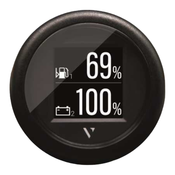
DISPLAY LAYOUT DISPLAY LAYOUT SINGLE LAYOUT Symbol Indicates, which data type is displayed right now. For the data types, which support this function, there is also the instance indicated here. Unit Shows the unit of the currently displayed data. For some data types it’s possible to change the unit in the settings. -
Page 19: Alarm Display
DISPLAY LAYOUT ALARM DISPLAY Single data layout Dual data layout When an alarm occurs the bar-graph turns red, When an alarm occurs on any of the two displayed and a red alarm symbol is displayed in the top data, the numeric digits of the affected data part of the display between the data symbol and become red. -
Page 20: Technical Data
TECHNICAL DATA TECHNICAL DATA DATASHEET Screen 1.44-inch TFT color display, sun-readable, transmissive Screen resolution 125 x 125 Pixel Rated voltage 12 V / 24 V Operating voltage 9 - 32 V with overvoltage and reverse polarity protection Current consumption 50 mA with maximum illumination intensity Resistive (0 - 400 Ω) Analog inputs Frequency (W, Ind. - Page 21 TECHNICAL DATA SUPPORTED NMEA 2000® PGNS Description ISO Address Claim 60928 ISO Request 59904 ISO Transport Protocol, Data Transfer 60160 ISO Transport Protocol, Connection 60416 Management ISO Acknowledgment 59392 NMEA - Request group function 126208 System Time 126992 Heartbeat 126993 Configuration Information 126998 Product Information...
-
Page 22: Accessories
Front ring - Flat Chrome * A2C5318602301 Visit http://www.veratron.com for the complete list of available accessories. * The chrome front ring may interfere with NFC programming due to the metal particles contained in the chrome. Make sure that you configure the VL Flex before installing the chrome front ring! - Page 23 Partial or complete distribution, translation or reproduction of this document is strictly prohibited without the prior written consent of veratron AG, with the exception of the following measures: - Print all or part of the document in its original size.
- Page 24 VL FLEX 52MM SERIES VL FLEX 52 NMEA 2000 BEDIENUNGSANLEITUNG rev. AD B000882...
- Page 25 INHALT INHALT Inhalt ......................2 Einführung....................3 Verpackungsinhalt ....................3 Das All-in-One-Gerät ....................3 Kontaktlose Konfiguration ..................3 Architektur ........................3 Sicherheitshinweise .................. 4 Während des Einbaus beachten ................ 4 Nach dem Einbau beachten ................. 5 Elektrischer Anschluss ..................... 5 Installation ....................7 Vor der Installation ....................
-
Page 26: Einführung
EINFÜHRUNG EINFÜHRUNG VERPACKUNGSINHALT Artikelnummer Beschreibung B00043501 oder 1x VL Flex 52 – NMEA 2000 (schwarz B00111301 oder weiss) A2C5205947101 1x 52 mm Spinlock-Mutter A2C9582260001 1x Kabelbaum B000100 1x Sicherheitsanweisungen DAS ALL-IN-ONE-GERÄT Das VL Flex kann dank seines, auch in starkem Sonnenlicht lesbaren, 1,44-Zoll-TFT-Displays, das in ein Standardgehäuse mit 52 mm Durchmesser eingebettet ist, einfach als das Anzeigegerät konfiguriert werden, welches Sie benötigen. -
Page 27: Sicherheitshinweise
SICHERHEITSHINWEISE SICHERHEITSHINWEISE • Nicht rauchen! Kein offenes Feuer oder Wärmequellen! • Das Produkt wurde unter Beachtung der • Beachten Sie eventuelle Veränderungen am grundlegenden Sicherheitsanforderungen der Fahrzeug, die beim Einbau zu berücksichtigen EG-Richtlinien und dem anerkannten Stand sind! • Für den Einbau sind Grundkenntnisse der der Technik entwickelt, gefertigt und geprüft. -
Page 28: Nach Dem Einbau Beachten
SICHERHEITSHINWEISE • Bei notwendigen Arbeiten ohne flüchtigen elektronischen Speicher ihre eingegebenen Werte verlieren und neu Spannungsunterbrechung darf nur mit programmiert werden müssen. isoliertem Werkzeug gearbeitet werden. • Lassen Sie bei Bootsmotoren vor Beginn der • Benutzen Sie zum Messen von Spannungen Arbeiten im Motorraum bei Benzinmotoren und Strömen im Fahrzeug/ Maschine bzw. - Page 29 SICHERHEITSHINWEISE • Achtung: Kurzschlussgefahr durch fehlerhafte • Achten Sie besonders auf einwandfreie Verbindungsstellen oder beschädigte Kabel. Masseverbindungen. • Kurzschlüsse im Bordnetz können • Falschanschlüsse können zu Kurzschlüssen Kabelbrände, Batterieexplosionen und führen. Schliessen Sie die Kabel nur Beschädigungen anderer elektronischer entsprechend dem elektrischen Anschlussplan Systeme verursachen.
-
Page 30: Installation
INSTALLATION INSTALLATION Vor Beginn der Arbeiten ist der Minuspol der Batterie abzuklemmen, da sonst Kurzschlussgefahr besteht. Wenn das Fahrzeug über Zusatzbatterien verfügt, müssen ggf. auch die Minuspole dieser Batterien abgeklemmt werden! Kurzschlüsse können Kabelbrände, Batterieexplosionen und Beschädigungen von anderen elektronischen Systemen verursachen. Bitte beachten Sie, dass beim Abklemmen der Batterie alle flüchtigen elektronischen Speicher ihre eingegebenen Werte verlieren und neu programmiert werden müssen. -
Page 31: Montage Mit Spinlock-Mutter
INSTALLATION MONTAGE MIT SPINLOCK-MUTTER Konventionelle Montage. (Gerät wird von vorn in die Bohrung gesteckt). Die Panelstärke kann im Bereich von 0,5 bis 20 mm liegen. Die Bohrung muss einen Durchmesser von 53 mm haben [B]. • Bohrungen und Einbauöffnungen nicht in tragende oder stabilisierende Streben oder Holme anbringen! •... -
Page 32: Bündige Montage
INSTALLATION BÜNDIGE MONTAGE Die empfohlene Panelstärke liegt bei 1,5 bis 3mm. Die Bohrung muss einen Durchmesser von 48,1 mm haben [A]. Achten Sie darauf, dass der Einbauort eben ist und keine scharfen Kanten aufweist. • Bohrungen und Einbauöffnungen nicht in tragende oder stabilisierende Streben oder Holme anbringen! •... -
Page 33: Anschlüsse
ANSCHLÜSSE ANSCHLÜSSE PINBELEGUNG Pin Nr. Kabelfarbe Beschreibung KL. 15 – Batterie 12 / 24 V Schwarz KL. 31 – Masse Grün / Rot Signal - Frequenzsensor Gelb / Rot Signal - Widerstandssensor Blau / Weiss LIN-Bus Rot / Weiss Beleuchtung Tag/Nacht NMEA 2000 High (am M12- Stecker) NMEA 2000 Low (am M12-... -
Page 34: Nmea 2000® Pinbelegung
ANSCHLÜSSE NMEA 2000® PINBELEGUNG Pin Nr. Beschreibung NET-H (CAN H) NET-L (CAN L) Micro-C M12 5-poliger Stecker Männlich, Kabel-Ansicht ANSCHLUSS AN DAS NMEA 2000® NETZWERK Nach Abschluss der Montage kann das Gerät über die dafür vorgesehene Buchse an der Verkabelung mit dem NMEA 2000®-Netzwerk verbunden werden. -
Page 35: Anschluss Frequenzeingang
ANSCHLÜSSE ANSCHLUSS FREQUENZEINGANG Bezeichnungen im Anschlussplan: 15 – KL. 15 – geschaltetes Plus 12/24 V (Zündung) 31 – KL. 31 – Masse F1 – Sicherung 3A (nicht enthalten) S1 – Beleuchtungsschalter Tag/Nacht (nicht enthalten) ANSCHLUSS WIDERSTANDSSENSOR Bezeichnungen im Anschlussplan: 15 – KL. 15 – geschaltetes Plus 12/24 V (Zündung) 31 –... -
Page 36: Konfiguration
KONFIGURATION KONFIGURATION VL FLEX CONFIGURATOR APP Um das VL Flex zu konfigurieren, müssen einige Parameter konfiguriert werden, z. B. der Anzeigetyp, der angeschlossene Sensor und seine Kalibrierung oder die Alarmschwelle. Dies ist über die Smartphone-App “VL Flex Configurator” möglich, die sowohl für Android- als auch für iOS- Geräte kostenlos aus den Stores heruntergeladen werden kann. -
Page 37: Analoge Sensoren Konfigurieren
System vorhanden sind. Configuration: In die Tabelle soll die Sensorkurve eingetragen werden, die das Verhalten des angeschlossenen Sensors beschreibt. Für Veratron-Sensoren sind die Kurven vordefiniert und können durch Drücken auf den entsprechenden Sensor aus dem Dropdown-Menü "Characteristics" in die Tabelle importiert werden. -
Page 38: Helligkeit Und Uhr
KONFIGURATION HELLIGKEIT UND UHR Diese Parameter werden in der Registerkarte "Settings" eingestellt. Illumination: Die Helligkeit des Bildschirms für den Tag- und Nachtmodus kann mit den Schiebereglern gewählt werden. Der Tag- oder Nachtmodus hängt vom angelegten Signal am Beleuchtungseingang (Pin 6 - Rot/Weiss) ab. Offset: Die Zeit wird nicht intern gezählt, sondern kann nur über NMEA 2000 empfangen werden. - Page 39 KONFIGURATION Widerstands Frequenz Alarm Anzeigetyp Einheit Kalibrierungen Sensor Sensor verfügbar Tiefe 128267 (Depth) (unten) 0 – 90 Ω 3 – 180 Ω Kraftstofffüllstand 240 – 33 Ω 127505 (Fuel Level) (unten) 90 – 4 Ω 105 – 4 Ω 3 – 180 Ω Frischwasserfüllstand 240 –...
-
Page 40: Display-Layout
DISPLAY-LAYOUT DISPLAY-LAYOUT EINZELLAYOUT Symbol Zeigt an, welcher Wert gerade auf dem Display angezeigt wird. Bei den Messwerten, für welche diese Funktion unterstützt wird, wird auch die Instanz angezeigt. Masseinheit Zeigt die Masseinheit des Messwertes an. Bei manchen Werten ist die Einheit per Konfigurationsapp verstellbar. -
Page 41: Alarm-Display
DISPLAY-LAYOUT ALARM-DISPLAY Im Einzellayout Im Doppellayout Sobald ein Alarm ausgelöst wird, ändert sich die Wenn ein Alarm bei einem der beiden Messwerte Farbe des Balkendiagramms in rot und ein kleines auftritt, werden die Ziffern des Zahlenwertes rot Alarmsymbol wird im oberen Teil des Displays, dargestellt. -
Page 42: Technische Daten
TECHNISCHE DATEN TECHNISCHE DATEN DATENBLATT Bildschirm 1,44-Zoll-TFT-Farbdisplay, sonnenlesbar, transmissiv Bildschirmauflösung 125 x 125 Pixel Nennspannung 12 V / 24 V Betriebsspannung 9 – 32 V mit Überspannungs- und Verpolungschutz Stromaufnahme 50 mA mit maximaler Beleuchtungsintensität Resistiv (0 – 400 Ω) Analoge Eingänge Frequenz (W, Ind., Hall, Generator) Digitale Eingänge... - Page 43 TECHNISCHE DATEN UNTERSTÜTZTE NMEA 2000® PGNS Description ISO Address Claim 60928 ISO Request 59904 ISO Transport Protocol, Data Transfer 60160 ISO Transport Protocol, Connection 60416 Management ISO Acknowledgment 59392 NMEA - Request group function 126208 System Time 126992 Heartbeat 126993 Configuration Information 126998 Product Information...
-
Page 44: Zubehör
Frontring – Flach Chrom * A2C5318602301 Besuchen Sie http://www.veratron.com für die vollständige Liste der verfügbaren Zubehöre. * Der Chrom Frontring kann aufgrund der im Chrom enthaltenen Metallpartikel die NFC-Programmierung beeinträchtigen. Stellen Sie sicher, dass Sie das VL Flex-Gerät konfigurieren, bevor Sie den Chrom Frontring... - Page 45 • Drucken Sie das Dokument ganz oder teilweise in seiner Originalgrösse. • Vervielfältigung des Inhalts ohne Änderung und Erklärung durch die Veratron AG als Urheberrechtsinhaber. Die Veratron AG behält sich das Recht vor, Änderungen oder Verbesserungen an der zugehörigen Dokumentation ohne vorherige Ankündigung vorzunehmen. Genehmigungsanträge, zusätzliche Kopien dieses Handbuchs oder technische Informationen dazu sind an die veratron AG zu richten.
- Page 46 VL FLEX 52MM SERIES VL FLEX 52 NMEA 2000 ISTRUZIONI PER L’USO rev. AD B000882...
-
Page 47: Indice
INDICE INDICE Indice ......................2 Introduzione ....................3 Contenuto della confezione ................. 3 L’indicatore all-in-one ..................... 3 Configurazione contactless .................. 3 Architettura ........................3 Indicazioni per la sicurezza ..............4 Sicurezza durante il montaggio ................4 Sicurezza dopo il montaggio................. 5 Collegamento elettrico ................... 5 Installazione .................... -
Page 48: Introduzione
INTRODUZIONE INTRODUZIONE CONTENUTO DELLA CONFEZIONE Numero di articolo Descrizione B00043501 / 1x VL Flex - NMEA 2000 (nero B00111301 o bianco) A2C5205947101 1x 52 mm Spinlock di fissaggio A2C9582260001 1x Cablaggio B000100 1x Istruzioni sula sicurezza L’INDICATORE ALL-IN-ONE Il dispositivo VL Flex può essere facilmente configurato per essere lo strumento di cui hai bisogno, grazie al suo display TFT da 1,44 pollici leggibile al sole incorporato in un corpo standard di diametro 52 mm. -
Page 49: Indicazioni Per La Sicurezza
• Modifiche o manipolazioni del prodotto per cui è previsto. Le conseguenze di un utilizzo improprio del prodotto possono veratron possono compromettere la sicurezza. causare lesioni a persone e danni a cose o Non sono pertanto ammesse manovre di all’ambiente. Prima del montaggio accertarsi modifica o manipolazione. -
Page 50: Sicurezza Dopo Il Montaggio
INDICAZIONI PER LA SICUREZZA memoria elettronica transitoria andranno persi assolutamente alle indicazioni di sicurezza del e dovranno essere riprogrammati. produttore dell’utensile. • Nelle barche con motore a benzina accendere • Per i lavori per cui è necessario interrompere la il ventilatore del motore prima di iniziare a tensione utilizzare esclusivamente un utensile lavorare al vano motore. - Page 51 INDICAZIONI PER LA SICUREZZA vanno dotati di giunti di testa saldabili e • Per il funzionamento dell’apparecchio con devono essere sufficientemente isolati. alimentatori di rete assicurarsi che gli • Verificare in particolare l’efficienza dei alimentatori siano stabili e che siano stati prodotti in conformità...
-
Page 52: Installazione
INSTALLAZIONE INSTALLAZIONE Prima di iniziare a lavorare staccare il morsetto del polo negativo della batteria per evitare il rischio di corto circuito. Se il veicolo è dotato di batterie supplementari occorre staccare eventualmente anche il polo negativo di tutte le batterie. I corto circuiti possono bruciare i cavi, far esplodere le batterie e causare danni ad altri sistemi elettronici. -
Page 53: Montaggio Tramite Spinlock
INSTALLAZIONE MONTAGGIO TRAMITE SPINLOCK Montaggio convenzionale. (Lo strumento viene inserito nel foro dalla parte anteriore). Lo spessore del pannello può essere da 0,5 a 20 mm. Il foro deve avere un diametro di 53 mm [B]. • Non praticare fori né aperture di montaggio in sostegni o longheroni portanti o stabilizzanti! •... -
Page 54: Montaggio A Filo
INSTALLAZIONE MONTAGGIO A FILO Lo spessore consigliato del pannello è di circa 1,5 mm – 3 mm. Il foro deve avere un diametro di 48,1 mm. [A] Assicurarsi che il punto di montaggio sia piano e privo di bordi taglienti. •... -
Page 55: Connessioni
CONNESSIONI CONNESSIONI PIEDINATURA Colore del Pin No. Descrizione filo Rosso KL. 15 – Alimentazione 12 / 24 V Nero KL. 31 – Massa Verde / Segnale sensore in frequenza Rosso Giallo / Segnale sensore resistivo Rosso Blu / Bianco LIN bus Rosso / Illuminazione Giorno/Notte Bianco... -
Page 56: Piedinatura Connettore Nmea 2000
CONNESSIONI PIEDINATURA CONNETTORE NMEA 2000® Pin No. Descrizione NET-H (CAN H) NET-L (CAN L) Micro-C M12 5 poles plug Maschio, vista cavo CONNESSIONE ALLA RETE NMEA 2000® Una volta completata l'installazione è possibile interfacciare il dispositivo alla rete NMEA 2000® tramite la presa dedicata sul cablaggio. Assicurarsi di serrare il connettore M12 avvitandolo sulla sua controparte, in modo da preservarne la tenuta stagna. -
Page 57: Connessione Sensore In Frequenza
CONNESSIONI CONNESSIONE SENSORE IN FREQUENZA Denominazioni nello schema elettrico: 15 – KL. 15 – Positivo accensione 12/24 V 31 – KL. 31 – Massa F1 – Fusibile 3A (non incluso) S1 – Selettore illuminazione Giorno/Notte (non incluso) CONNESSIONE SENSORE RESISTIVO Denominazioni nello schema elettrico: 15 –... -
Page 58: Configurazione
CONFIGURAZIONE CONFIGURAZIONE VL FLEX CONFIGURATOR APP Per configurare il VL Flex 52- NMEA 2000, è necessario configurare alcuni parametri, come il tipo di indicatore, il sensore collegato e la sua calibrazione o la soglia di allarme. Ciò è possibile tramite l'App per smartphone “VL Flex Configurator”, scaricabile gratuitamente dagli store sia per dispositivi Android che iOS. -
Page 59: Configurare Gli Ingressi Analogici
Configuration: La curva che descrive il comportamento del sensore collegato deve essere inserita nella tabella. Per i sensori Veratron le curve sono predefinite e possono essere importate nella tabella selezionando la curva corrispondente dal menu a discesa "Caratteristiche". -
Page 60: Luminosità E Orologio
CONFIGURAZIONE LUMINOSITÀ E OROLOGIO Per modificare questi parametri, aprire la scheda "Settings". Illumination: Utilizzare i cursori per definire i livelli di luminosità per la modalità giorno e notte. La modalità giorno o notte dipende dal segnale applicato all'ingresso di illuminazione (Pin 6 - Rosso/Bianco). - Page 61 CONFIGURAZIONE Sensore Sensore Allarme Tipo di indicatore Unità Calibrazioni resistivo in freq. disponibile Profondità 128267 (Depth) (inferiore) Orologio 126992 (Clock) 0 – 90 Ω 3 – 180 Ω Livello Carburante 240 – 33 Ω 127505 (Fuel Level) 90 – 4 Ω 105 –...
-
Page 62: Disposizione Del Display
DISPOSIZIONE DEL DISPLAY DISPOSIZIONE DEL DISPLAY LAYOUT SINGOLO Simbolo del dato visualizzato Indica quale tipo di dati viene visualizzato in questo momento. Per i tipi di dati che supportano questa funzione, c'è anche l'istanza indicata qui. Unità del valore misurato Mostra l'unità... -
Page 63: Alarm Display
DISPOSIZIONE DEL DISPLAY ALARM DISPLAY Layout Singolo Doppio Layout Quando si verifica un allarme, il diagramma a Quando si verifica un allarme su uno dei due dati barre diventa rosso e nella parte superiore del visualizzati, le cifre numeriche del dato interessato display viene visualizzato un simbolo di allarme diventano rosse. -
Page 64: Dati Tecnici
DATI TECNICI DATI TECNICI DATASHEET Display Display a colori TFT 1.44”, leggibile al sole, trasmissivo Risoluzione display 125 x 125 pixels Tensione nominale 12 V / 24 V 9 – 32 V con protezione per sovralimentazione e polarità Tensione di esercizio inversa Consumo di corrente 50 mA con massima intensità... -
Page 65: Pgn Nmea 2000® Supportati
DATI TECNICI PGN NMEA 2000® SUPPORTATI Description ISO Address Claim 60928 ISO Request 59904 ISO Transport Protocol, Data Transfer 60160 ISO Transport Protocol, Connection 60416 Management ISO Acknowledgment 59392 NMEA - Request group function 126208 System Time 126992 Heartbeat 126993 Configuration Information 126998 Product Information... -
Page 66: Accessori
Cornice – Piatta Cromata * A2C5318602301 Visita http://www.veratron.com per la list completa degli accessori disponibili. * la cornice cromata potrebbe interferire con la programmazione NFC a causa delle particelle metalliche contenute nella cromatura. Assicurarsi di configurare il VL Flex PRIMA di installare la cornice cromata! - Page 67 • Copia dei contenuti senza alcuna modifica e dichiarazione di Veratron AG come titolare del copyright. Veratron AG si riserva il diritto di apportare modifiche o miglioramenti alla relativa documentazione senza preavviso. Richieste di autorizzazione, copie aggiuntive di questo manuale o informazioni tecniche su quest'ultimo, devono essere indirizzate a veratron AG.
- Page 68 VL FLEX 52MM SERIES VL FLEX 52 NMEA 2000 MANUEL DE L'UTILISATEUR rev. AD B000882...
- Page 69 CONTENU CONTENU Contenu ......................2 Introduction ....................3 Contenu de l’emballage..................3 L’indicateur tout en un .................... 3 Configuration sans contact ................... 3 Architecture ........................3 Consignes de sécurité ................4 Sécurité Pendant le montage ................4 Après le montage ....................... 5 Raccordement électrique ..................
-
Page 70: Introduction
INTRODUCTION INTRODUCTION CONTENU DE L’EMBALLAGE Numéro de pièce Désignation B00043501 ou 1x VL Flex 52 – NMEA 2000 (noir B00111301 ou blanc) A2C5205947101 1x 52 mm écrou Spinlock A2C9582260001 1x Faisceau de câbles B000100 1x Consignes de sécurité L’INDICATEUR TOUT EN UN Le VL Flex peut être facilement configuré... -
Page 71: Consignes De Sécurité
• Le fait de modifier ou de manipuler le produit à l’usage prévu de ce produit peut causer des dommages corporels, matériels ou Veratron peut avoir des conséquences sur la environnementaux. Avant l’installation, sécurité. C’est pourquoi il ne doit pas être informez-vous sur le type du véhicule à... -
Page 72: Après Le Montage
CONSIGNES DE SÉCURITÉ de batteries supplémentaires, couper d’une fraise conique, d’une scie à guichet, également les pôles négatifs de ces batteries! d’une scie sauteuse ou d’une lime puis installez. Les courts-circuits peuvent causer des Ebarbez les arêtes. Respecter impérativement incendies de câbles, des explosions de les consignes de sécurité... - Page 73 CONSIGNES DE SÉCURITÉ • Veillez à ce que les câbles ne soient soumis à • Des courts-circuits au niveau du réseau de aucune force de traction, de pression ou de bord peuvent entraîner des incendies de cisaillement. câbles, des explosions de batteries et •...
-
Page 74: Installation
INSTALLATION INSTALLATION Avant de commencer à travailler, débrancher le pôle négatif de la batterie, pour éviter tout risque de court-circuit. Si le véhicule est équipé de batteries supplémentaires, il y a lieu, le cas échéant, de débrancher également le pôle négatif de ces batteries. Les courts-circuits peuvent mettre le feu aux câbles ou provoquer l’explosion des batteries et peuvent endommager les systèmes électroniques. -
Page 75: Montage Avec Spinlock
INSTALLATION MONTAGE AVEC SPINLOCK Montage conventionnel (appareil inséré par l’avant dans l’orifice prévu pour son emplacement). L’épaisseur du panneau peut osciller entre 0,5 mm et 20 mm. Percer au diamètre de 53 mm [B]. • Ne pas effectuer de perçage ni d’ouverture dans les montants ou longerons porteurs ou stabilisateurs. •... -
Page 76: Montage Affleurant
INSTALLATION MONTAGE AFFLEURANT L’épaisseur de panneau recommandée est de 1,5 à 3 mm. Le perçage doit avoir un diamètre de 48,1 mm [A]. Veiller à ce que l’emplacement de montage soit plan et ne présente aucune arête vive. • Ne pas effectuer de perçage ni d’ouverture dans les montants ou longerons porteurs ou stabilisateurs. •... -
Page 77: Connexion De L'appareil
CONNEXION DE L‘APPAREIL CONNEXION DE L’APPAREIL BROCHAGE Broche Couleur Description Rouge KL. 15 – Batterie 12 / 24 V Noir KL. 31 – Masse Vert / Rouge Signal du capteur de fréquence Jaune / Signal du capteur résistif Rouge Bleu / Blanc LIN bus Rouge / Blanc Éclairage Jour/Nuit... -
Page 78: Brochage Du Connecteur Nmea 2000
CONNEXION DE L‘APPAREIL BROCHAGE DU CONNECTEUR NMEA 2000® Broche Description NET-H (CAN H) Micro-C M12 5 broches NET-L (CAN L) Mâle, vue du câble CONNEXION AU RÉSEAU NMEA 2000® Une fois l'installation terminée, l'appareil peut être interfacé avec le réseau NMEA 2000®... -
Page 79: Connexion Du Capteur De Fréquence
CONNEXION DE L‘APPAREIL CONNEXION DU CAPTEUR DE FRÉQUENCE Désignations des pièces mentionnées dans le plan de connexion : 15 – KL. 15 – Allumage plus 12/24 V 31 – KL. 31 – Masse F1 – Fusible 3A (non inclus) S1 – Interrupteur d'éclairage jour / nuit (non inclus) CONNEXION DU CAPTEUR RÉSISTIF Désignations des pièces... -
Page 80: Configuration
CONFIGURATION CONFIGURATION VL FLEX CONFIGURATOR APP Pour configurer le VL Flex 52, il est nécessaire de configurer certains paramètres, tels que le type d'indicateur, le capteur connecté et son étalonnage ou le seuil d'alarme. Ceci est possible grâce à l'application pour smartphone «VL Flex Configurator », qui peut être téléchargée gratuitement dans les magasins d’applications pour les appareils Android et iOS. -
Page 81: Connecter Un Capteur Analogique
Configuration : la courbe du capteur décrivant le comportement du capteur raccordé doit être inscrite dans le tableau. Pour les capteurs Veratron, les courbes sont prédéfinies et peuvent être importées dans le tableau en appuyant sur le capteur correspondant dans le menu déroulant "Characteristics". -
Page 82: Luminosité Et Horloge
CONFIGURATION LUMINOSITÉ ET HORLOGE Ces paramètres sont réglés dans l'onglet "Settings". Illumination : utilisez les curseurs pour définir les niveaux de luminosité pour le mode jour et le mode nuit. Le mode jour ou nuit dépend du signal appliqué à l'entrée d'éclairage (broche 6 - rouge/blanc). Clock Offset : l'heure n'est pas comptée en interne, elle ne peut être reçue que via NMEA 2000. - Page 83 CONFIGURATION Capteur Capteur Alarme Type d'indicateur Unité Étalonnages résistif de fréq. disponible Profondeur 128267 (Depth) (inférieur) Horloge 126992 (Clock) 0 – 90 Ω 3 – 180 Ω Niveau de carburant 240 – 33 Ω 127505 (Fuel Level) 90 – 4 Ω 105 –...
-
Page 84: Disposition De L'affichage
DISPOSITION DE L'AFFICHAGE DISPOSITION DE L'AFFICHAGE AFFICHAGE SIMPLE Symbole Indique le type de données affiché en ce moment. Pour les types de données qui supportent cette fonction, l'instance est également indiquée ici. Unité de masse Affiche l'unité des données actuellement affichées. Pour certains types de données, il est possible de modifier l'unité... -
Page 85: Alarm Display
DISPOSITION DE L'AFFICHAGE ALARM DISPLAY Disposition des données simples Présentation des données doubles Lorsqu'une alarme se produit, le graphique à Lorsqu'une alarme se produit sur l'une des deux barres devient rouge et un symbole d'alarme données affichées, les chiffres numériques de la rouge est affiché... -
Page 86: Données Techniques
DONNÉES TECHNIQUES DONNÉES TECHNIQUES FICHE TECHNIQUE Écran Écran couleur TFT de 1,44”, lisible au soleil, transmissif Résolution de l'écran 125 x 125 pixels Tension nominale 12 V / 24 V Tension de fonctionnement 9 – 32 V Protection contre l'inversion de polarité et suralimentation Consommation de courant 50 mA avec une intensité... -
Page 87: Pgn Nmea 2000® Pris En Charge
DONNÉES TECHNIQUES PGN NMEA 2000® PRIS EN CHARGE Description ISO Address Claim 60928 ISO Request 59904 ISO Transport Protocol, Data Transfer 60160 ISO Transport Protocol, Connection Management 60416 ISO Acknowledgment 59392 NMEA - Request group function 126208 System Time 126992 Heartbeat 126993 Configuration Information... -
Page 88: Accessoires
Lunette – Plate Chromée * A2C5318602301 Visitez http://www.veratron.com pour la liste complète des accessoires disponibles. * la lunette chromée peut interférer avec la programmation NFC en raison des particules métalliques contenues dans le chrome. Assurez-vous de configurer le VL Flex AVANT d'installer la lunette chromée ! - Page 89 • Imprimez le document dans sa taille d'origine, en tout ou en partie. • Copie du contenu sans aucune modification et déclaration de Veratron AG en tant que titulaire des droits d'auteur. Veratron AG se réserve le droit d'apporter des modifications ou des améliorations à la documentation associée sans préavis.
- Page 90 VL FLEX 52MM SERIES VL FLEX 52 NMEA 2000 MANUAL DEL USUARIO rev. AD B000882...
- Page 91 CONTENIDO CONTENIDO Contenido .....................2 Inicio ......................3 Contenido del embalaje ..................3 El indicador all-in-one ..................... 3 Configuración sin contacto ................... 3 Arquitectura ......................... 3 Informaciones de seguridad ..............4 Observar durante el montaje ................4 Observar después del montaje ................5 Conexión eléctrica .....................
-
Page 92: Contenido
INICIO INICIO CONTENIDO DEL EMBALAJE Número de artículo Descripción B00043501 / 1x VL Flex 52 – NMEA 2000 (negro B00111301 o blanco) A2C5205947101 1x 52 mm Tuerca racor A2C9582260001 1x Cable de alimentación y datos B000100 1x Informaciones de seguridad EL INDICADOR ALL-IN-ONE El VL Flex se puede configurar fácilmente para que sea la herramienta que necesita, gracias a su pantalla TFT de 1,44”... -
Page 93: Informaciones De Seguridad
• Utilice nuestro producto sólo para el fin • Modificaciones o manipulaciones en el previsto. Las consecuencias de un uso del producto veratron pueden influir producto no conforme con las negativamente en la seguridad. ¡Por tanto, no especificaciones, pueden ser daños personales, se puede modificar ni manipular nada! •... -
Page 94: Observar Después Del Montaje
INFORMACIONES DE SEGURIDAD baterías adicionales, deben desembornarse ampliar los orificios y terminarlos con una fresa también, si es necesario, los polos negativos de cónica, sierra de punta, sierra de calar o lima. esas baterías. Los cortocircuitos pueden Desbarbar los bordes. Observar sin falta las originar incendios de cables, explosiones de indicaciones de seguridad del fabricante de la baterías y daños en otros sistemas electrónicos... - Page 95 INFORMACIONES DE SEGURIDAD modo que no se dañe o rompa ningún hilo baterías y daños en otros sistemas electrónicos conductor. del vehículo. Por tanto, todas las conexiones • ¡Soldar los empalmes de cables nuevos sólo para la alimentación de tensión deben estar provistas de conectores topes soldables y con el procedimiento de soldadura con estaño suficientemente aislados.
-
Page 96: Instalación
INSTALACIÓN INSTALACIÓN Antes de comenzar con los trabajos, deberá desembornarse el polo negativo de la batería, caso contrario existe peligro de cortocircuitos. ¡En el caso de que el vehículo disponga de baterías adicionales, también deberán desembornarse los polos negativos de esas baterías! Los cortocircuitos pueden ocasionar incendios de cables, explosiones de baterías y daños en otros sistemas electrónicos del vehículo. -
Page 97: Montaje Con Spinlock
INSTALACIÓN MONTAJE CON SPINLOCK Montaje convencional. (El instrumento se introduce por delante en la perforación). El espesor del panel puede ser de un margen de 0,5 hasta 20 mm. La perforación debe tener un diámetro de 53 mm [B]. • No practicar perforaciones ni aberturas para el montaje en travesaños o largueros portantes o estabilizadores. -
Page 98: Montaje A Ras
INSTALACIÓN MONTAJE A RAS El espesor recomendado del panel es de 1,5 a 3 mm. La perforación debe tener un diámetro de 48,1 mm. [A] Cerciórese de que el lugar de montaje esté plano y no presente cantos vivos. • No practicar perforaciones ni aberturas para el montaje en travesaños o largueros portantes o estabilizadores. -
Page 99: Conexiones
CONEXIONES CONEXIONES PINOUT Color Función Rojo KL. 15 – Alimentación 12 / 24 V Negro KL. 31 – Masa (GND) Verde / Rojo Señal del sensor de frecuencia Amarillo / Rojo Señal de sensor resistivo Azul / Blanco LIN bus Rojo / Blanco Iluminación Día / Noche NMEA 2000 High (en el conector M12) -
Page 100: Conector Nmea 2000
CONEXIONES CONECTOR NMEA 2000® Función Blindaje NET-S (V+) NET-C (V-) NET-H (CAN High) NET-L (CAN Low) Micro-C M12 5 polos Macho, vista cable CONEXIÓN A LA RED NMEA 2000® Una vez que se completa la instalación, el dispositivo se puede conectar a la red NMEA 2000®... -
Page 101: Conexión Del Sensor De Frecuencia
CONEXIONES CONEXIÓN DEL SENSOR DE FRECUENCIA Designación dentro del esquema de conexiones: 15 – KL. 15 – Positivo conectado (encendido) 12/24 31 – KL. 31 – Masa (GND) F1 – Fusible 3A (non incluso) S1 – Selector de iluminación Día/Noche (no incluido) CONEXIÓN DEL SENSOR RESISTIVO Designación dentro del esquema de conexiones:... -
Page 102: Configuración
CONFIGURACIÓN CONFIGURACIÓN VL FLEX CONFIGURATOR APP Para configurar el VL Flex 52 – NMEA 2000 es necesario configurar algunos parámetros, como el tipo de indicador, el sensor conectado y su calibración o el umbral de alarma. Esto es posible a través de la aplicación para teléfonos inteligentes “VL Flex Configurator”, que se puede descargar de forma gratuita desde las tiendas para dispositivos Android e iOS. -
Page 103: Configurar Un Sensor Analógico
Configuration: La curva del sensor que describe el comportamiento del sensor conectado debe introducirse en la tabla. Para los sensores Veratron, las curvas están predefinidas y pueden importarse a la tabla pulsando sobre el sensor correspondiente en el menú desplegable "Characteristics". -
Page 104: Brillo Y Reloj
CONFIGURACIÓN Capacity: Especificación de la capacidad de la batería. El número se indica en la batería. En el caso de un pack de baterías, deben sumarse los números de las diferentes baterías. BRILLO Y RELOJ Estos parámetros se ajustan en la pestaña Ajustes. Illumination: Utilice los controles deslizantes para ajustar los niveles de brillo para el modo diurno y nocturno. - Page 105 CONFIGURACIÓN Sensor Sensor de Alarma Tipo de indicador Unidad Calibraciones resistivo frecuencia disponible Speed Over Ground km/h 129026 (SOG) Course Over Ground 129026 (COG) Profundidad 128267 (Depth) (inferior) Reloj 126992 (Clock) 0 – 90 Ω 3 – 180 Ω Nivel de combustible 240 –...
-
Page 106: Diseño De La Pantalla
DISEÑO DE LA PANTALLA DISEÑO DE LA PANTALLA SINGLE LAYOUT Símbolo Indica qué tipo de datos se muestra en este momento. Para los tipos de datos que admiten esta función, también se indica aquí la instancia. Unit Shows the unit of the currently displayed data. For some data types it’s possible to change the unit in the settings. -
Page 107: Alarm Display
DISEÑO DE LA PANTALLA ALARM DISPLAY Disposición de los datos individuales Disposición de los datos duales Cuando se produce una alarma, el gráfico de Cuando se produce una alarma en cualquiera de barras se vuelve rojo y se muestra un símbolo de los dos datos mostrados, los dígitos numéricos del alarma rojo en la parte superior de la pantalla, dato afectado se vuelven rojos. -
Page 108: Datos Técnicos
DATOS TÉCNICOS DATOS TÉCNICOS FICHA DE DATOS Pantalla TFT a color de 1,44 ", legible a la luz del sol, Pantalla transmisiva Resolución de la pantalla 125 x 125 pixels Tensión nominal 12 V / 24 V 9 – 32 V con protecciones de sobretensión y polaridad Tensión de funcionamiento inversa Consumo de corriente... -
Page 109: Pgn Nmea 2000® Compatibles
DATOS TÉCNICOS PGN NMEA 2000® COMPATIBLES Description ISO Address Claim 60928 ISO Request 59904 ISO Transport Protocol, Data Transfer 60160 ISO Transport Protocol, Connection 60416 Management ISO Acknowledgment 59392 NMEA - Request group function 126208 System Time 126992 Heartbeat 126993 Configuration Information 126998 Product Information... -
Page 110: Accesorios
Biseles – Piatta Cromado * A2C5318602301 Visite http://www.veratron.com para obtener la lista completa de accesorios disponibles. * el marco cromado puede interferir con la programación NFC debido a las partículas metálicas contenidas en el cromo. ¡Asegúrese de configurar el VL Flex ANTES de instalar el marco cromado! - Page 111 • Imprima el documento en su tamaño original, total o parcialmente. • Copia del contenido sin ninguna modificación y declaración por parte de Veratron AG como titular de los derechos de autor. Veratron AG se reserva el derecho de realizar cambios o mejoras en la documentación relacionada sin previo aviso.
Need help?
Do you have a question about the VL FLEX Series and is the answer not in the manual?
Questions and answers