
Subscribe to Our Youtube Channel
Related Manuals for Veratron A2C59501987


Summary of Contents for Veratron A2C59501987
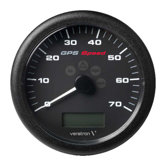
- Page 1 TIMELESS INSTRUMENTS VIEWLINE 110MM GPS SPEEDOMETERS USER MANUAL rev. AA...
-
Page 2: Table Of Contents
CONTENT CONTENT INTRODUCTION ..................3 Part Numbers ....................... 3 TECHNICAL DATA ..................3 SAFETY INFORMATION ................. 4 Safety During Installation ..................4 Safety After Installation ................... 5 Electrical Connection ....................5 MECHANICAL INSTALLATION ............6 Before the Assembly ....................6 Installation with Spinlock ..................7 Flush Mounting ...................... -
Page 3: Introduction
There are three different versions of this gauge, each with a different measurement range. Each device can be configured to work with metric, imperial and nautical measurement units. Part Number Range A2C59501987 A2C59501782 A2C59501781 TECHNICAL DATA Supply Voltage 12 V (8-16V operating range, with reverse polarity protection) Current consumption <... -
Page 4: Safety Information
• Use our product only as intended. Use of the • Modifications or manipulations to Veratron product for reasons other than its intended use products can affect safety. Consequently, you may lead to personal injury, property damage may not modify or manipulate the product! •... -
Page 5: Safety After Installation
SAFETY INFORMATION • The electrical indicator outputs and cables keyhole saws or files. Deburr edges. Follow the safety instructions of the tool manufacturer. connected to them must be protected from • Use only insulated tools, if work is necessary on direct contact and damage. -
Page 6: Mechanical Installation
MECHANICAL INSTALLATION MECHANICAL INSTALLATION WARNING Before beginning, disconnect the negative terminal on the battery, otherwise you risk a short circuit. If the vehicle is supplied by auxiliary batteries, you must also disconnect the negative terminals on these batteries! Short circuits can cause fires, battery explosions and damages to other electronic systems. Please note that when you disconnect the battery, all volatile electronic memories lose their input values and must be reprogrammed. -
Page 7: Installation With Spinlock
MECHANICAL INSTALLATION INSTALLATION WITH SPINLOCK Conventional assembly. (Instrument is put into the drill hole from the front). The panel thickness may be within a range of 0.5 to 20 mm. The drill hole must have a diameter of 111 mm. WARNING •... -
Page 8: Flush Mounting
MECHANICAL INSTALLATION FLUSH MOUNTING The recommended panel thickness is 1.5 to 3 mm. The drill hole must have a diameter of 105.4 mm. Ensure that the installation location is level and has no sharp edges. WARNING • Do not drill holes or ports in load-bearing or stabilizing stays or tie bars! •... -
Page 9: Installation With Brackets
MECHANICAL INSTALLATION INSTALLATION WITH BRACKETS Conventional assembly. (Instrument is put into the drill hole from the front). The panel width may be within a range of 0.5 to 20 mm. The drill hole must have a diameter of 111 mm. WARNING •... -
Page 10: Electrical Installation
ELECTRICAL INSTALLATION ELECTRICAL INSTALLATION WARNING • Refer to the safety rules described in the electrical connections section of the safety information chapter of this document! Depending on the configuration, insert the cable into the 8-pin contact enclosure according to the following pin assignment. -
Page 11: Lcd Operation
LCD OPERATION LCD OPERATION BASICS Press the key briefly (< 2sec.) to change the currently displayed value. Press the key longer (> 2sec.) to change to the next value. The display returns to normal operating mode if a key is not pressed for 30 seconds. Any settings you have made are not saved in this case. -
Page 12: Brightness
LCD OPERATION BRIGHTNESS 1. Connect pin 1 to terminal 30 (Bat. +) 2. Switch on the ignition (Term. 15, pin 4) Press the mode button repeatedly until the COG screen is displayed. Press and hold the mode button (>2 sec.). Press the mode button repeatedly (<... - Page 13 LCD OPERATION Trip time Activated (counting) At speeds above 2.6km/h (1.6 mph, 1.4 kn) Maximum value 99 hours 59 minutes 99:59 → Time separator blinking (1Hz) Trip time is available, trip time is being counted. Trip time is not being counted (speed below Time separator permanently on threshold or no fix).
-
Page 14: Accessories
Bezel – Black, Flat A2C5321074501 Bezel – Chrome, Round A2C5321076101 Bezel – Chrome, Triangular A2C5321076501 Bezel – Chrome, Flat A2C5321074701 Bezel – White, Round A2C5321076001 Bezel – White, Triangular A2C5321076401 Bezel – White, Flat A2C5321074601 Visit http://www.veratron.com for the complete list of accessories. - Page 15 Any distribution, translation or reproduction, partial or total, of the document is strictly prohibited unless with prior authorization in writing from Veratron AG, except for the following actions: • Printing the document in its original format, totally or partially.
- Page 16 TIMELESS INSTRUMENTS VIEWLINE 110MM GPS-TACHOMETER BEDIENUNGSANLEITUNG rev. AA...
- Page 17 INHALT INHALT VORSTELLUNG ..................3 Teilenummern ......................3 TECHNISCHE DATEN ................3 SICHERHEITSHINWEISE ............... 4 Während des Einbaus beachten ................ 4 Nach dem Einbau beachten ................. 5 Elektrischer Anschluss ..................... 5 MECHANISCHE INSTALLATION............7 Vor der Installation ....................7 Einbau mit Spinlock ....................8 Bündige Montage ......................
-
Page 18: Vorstellung
Es gibt drei verschiedene Versionen dieses Geräts, die sich durch den möglichen Messbereich unterscheiden. Jedes der Geräte kann so konfiguriert werden, dass es mit metrischen, imperialen und nautischen Masseinheiten arbeitet. Teilenummer Bereich A2C59501987 A2C59501782 A2C59501781 TECHNISCHE DATEN Versorgungsspannung 12 V (Betriebsbereich 8-16 V, mit Verpolungsschutz) Stromverbrauch <... -
Page 19: Sicherheitshinweise
SICHERHEITSHINWEISE SICHERHEITSHINWEISE WARNUNG • Nicht rauchen! Kein offenes Feuer oder Wärmequellen! • Das Produkt wurde unter Beachtung der • Beachten Sie eventuelle Veränderungen am grundlegenden Sicherheitsanforderungen der Fahrzeug, die beim Einbau zu berücksichtigen EG-Richtlinien und dem anerkannten Stand sind! • Für den Einbau sind Grundkenntnisse der der Technik entwickelt, gefertigt und geprüft. -
Page 20: Nach Dem Einbau Beachten
SICHERHEITSHINWEISE • Lassen Sie bei Bootsmotoren vor Beginn der • Bei notwendigen Arbeiten ohne Arbeiten im Motorraum bei Benzinmotoren Spannungsunterbrechung darf nur mit den Motorraumlüfter laufen. isoliertem Werkzeug gearbeitet werden. • Achten Sie auf den Verlauf von Leitungen oder • Benutzen Sie zum Messen von Spannungen Kabelsträngen, um diese bei Bohr- und und Strömen im Fahrzeug/ Maschine bzw. - Page 21 SICHERHEITSHINWEISE • Kurzschlüsse im Bordnetz können • Falschanschlüsse können zu Kurzschlüssen Kabelbrände, Batterieexplosionen und führen. Schliessen Sie die Kabel nur Beschädigungen anderer elektronischer entsprechend dem elektrischen Anschlussplan Systeme verursachen. Deshalb müssen alle • Bei Betrieb des Gerätes an Netzteilen Verbindungen der Spannungsversorgung mit verschweissbaren Stossverbindern versehen beachten Sie, dass das Netzteil stabilisiert sein und ausreichend isoliert sein.
-
Page 22: Mechanische Installation
MECHANISCHE INSTALLATION MECHANISCHE INSTALLATION WARNUNG Vor Beginn der Arbeiten ist der Minuspol der Batterie abzuklemmen, da sonst Kurzschlussgefahr besteht. Wenn das Fahrzeug über Zusatzbatterien verfügt, müssen ggf. auch die Minuspole dieser Batterien abgeklemmt werden! Kurzschlüsse können Kabelbrände, Batterieexplosionen und Beschädigungen von anderen elektronischen Systemen verursachen. -
Page 23: Einbau Mit Spinlock
MECHANISCHE INSTALLATION EINBAU MIT SPINLOCK Konventioneller Einbau. (Instrument wird von vorne in die Bohrung eingesetzt). Die Paneldicke kann in einem Bereich von 0,5 bis 20 mm liegen. Das Bohrloch muss einen Durchmesser von 111 mm haben. WARNUNG • Bohren Sie keine Löcher oder Öffnungen in tragende oder stabilisierende Streben oder Zugstangen! •... -
Page 24: Bündige Montage
MECHANISCHE INSTALLATION BÜNDIGE MONTAGE Die empfohlene Paneldicke beträgt 1,5 bis 3 mm. Das Bohrloch muss einen Durchmesser von 105,4 mm haben. Stellen Sie sicher, dass der Einbauort eben ist und keine scharfen Kanten aufweist. WARNUNG • Bohren Sie keine Löcher oder Öffnungen in tragende oder stabilisierende Streben oder Zugstangen! •... -
Page 25: Bügelmontage
MECHANISCHE INSTALLATION BÜGELMONTAGE Konventioneller Zusammenbau. (Instrument wird von vorne in die Bohrung eingesetzt). Die Plattenbreite kann in einem Bereich von 0,5 bis 20 mm liegen. Das Bohrloch muss einen Durchmesser von 111 mm haben. WARNUNG • Bohren Sie keine Löcher oder Öffnungen in tragende oder stabilisierende Streben oder Zugstangen! •... -
Page 26: Elektrische Installation
ELEKTRISCHE INSTALLATION ELEKTRISCHE INSTALLATION WARNUNG • Beachten Sie die Sicherheitsvorschriften, die im Abschnitt "Elektrische Anschlüsse" des Kapitels "Sicherheitshinweise" in diesem Dokument beschrieben sind! Stecken Sie das Kabel je nach Konfiguration entsprechend der folgenden Pin-Belegung in das 8-polige Kontaktgehäuse. Die Kontakte müssen hörbar einrasten. Stecken Sie nun den Stecker in das Gerät. -
Page 27: Lcd-Bedienung
LCD-BEDIENUNG LCD-BEDIENUNG GRUNDLAGEN Drücken Sie die Taste kurz (< 2 Sek.), um den aktuell angezeigten Wert zu ändern. Drücken Sie die Taste länger (> 2 Sek.), um zum nächsten Wert zu wechseln. Das Display kehrt in den normalen Betriebsmodus zurück, wenn 30 Sekunden lang keine Taste gedrückt wird. -
Page 28: Helligkeit
LCD-BEDIENUNG HELLIGKEIT 1. Pin 1 an Klemme 30 (Bat. +) anschliessen 2. Schalten Sie die Zündung ein (Kl. 15, Pin 4) Drücken Sie die Modus-Taste wiederholt, bis der COG- Bildschirm angezeigt wird. Halten Sie die Modus-Taste gedrückt (>2 Sek.). Drücken Sie die Modus-Taste wiederholt (< 2 Sek.), bis die gewünschte Helligkeit erreicht ist. - Page 29 LCD-BEDIENUNG Fahrzeit Aktiviert (zählt) Bei Geschwindigkeiten über 2,6km/h (1,6 mph, 1,4 kn) Maximaler Wert 99 Stunden 59 Minuten 99:59 → Zeittrennzeichen blinkend (1Hz) Die Fahrzeit ist verfügbar und wird gezählt. Zeittrennzeichen dauerhaft Die Fahrtzeit wird nicht gezählt (Geschwindigkeit eingeschaltet unter Schwellwert oder keine Position erkannt). Fahrstrecke / Trip Aktiviert (zählt) Bei Geschwindigkeiten über 2,6km/h (1,6 mph, 1,4 kn)
-
Page 30: Zubehör
A2C5321074501 Blende - chrom, rund A2C5321076101 Blende - chrom, dreieckig A2C5321076501 Blende - chrom, flach A2C5321074701 Blende - weiss, rund A2C5321076001 Blende - weiss, dreieckig A2C5321076401 Blende - weiss, flach A2C5321074601 Eine vollständige Liste des Zubehörs finden Sie unter http://www.veratron.com. - Page 31 Jegliche Verbreitung, Übersetzung oder Vervielfältigung des Dokuments, ganz oder teilweise, ist strengstens untersagt, es sei denn, es liegt eine schriftliche Genehmigung der Veratron AG vor, mit Ausnahme der folgenden Massnahmen: • Drucken des Dokuments in seinem ursprünglichen Format, ganz oder teilweise.
Need help?
Do you have a question about the A2C59501987 and is the answer not in the manual?
Questions and answers