Veratron VMH Series User Manual
Hide thumbs
Also See for VMH Series:
- User manual (103 pages) ,
- User manual (39 pages) ,
- User manual (58 pages)
Table of Contents
Advertisement
Quick Links
Advertisement
Table of Contents

Subscribe to Our Youtube Channel
Related Manuals for Veratron VMH Series


Summary of Contents for Veratron VMH Series
- Page 1 VMH SERIES VMH 14 USER MANUAL rev. AA...
-
Page 2: Table Of Contents
CONTENT CONTENT Introduction Packaging Content The All-in-one Gauge Contactless Configuration Safety information Safety during Installation Safety After installation Electrical Connections Installation Before the Assembly Installation with Spinlock Connection Device Pinout EasyLink Connection Display layout Display Sections Alarm Display Configuration VMH 14 Configurator App VMH 14 Configuration Supported Configurations Alarm Settings... -
Page 3: Introduction
INTRODUCTION PACKAGING CONTENT 1x VMH 14 1x 52 mm Rubber B001099 sealing gasket A2C53194838 1x 52 mm Mounting 1x Veratron card Spinlock B000101 A2C52059471 1x Safety manual B000100 THE ALL-IN-ONE GAUGE The VMH device can easily be configured to be... -
Page 4: Safety Information
• Use our product only as intended. Use of the • Modifications or manipulations to veratron product for reasons other than its intended use products can affect safety. Consequently, you may lead to personal injury, property damage may not modify or manipulate the product! •... -
Page 5: Safety After Installation
SAFETY INFORMATION • Drill small ports; enlarge and complete them, if • The electrical indicator outputs and cables necessary, using taper milling tools, saber saws, connected to them must be protected from keyhole saws or files. Deburr edges. Follow the direct contact and damage. -
Page 6: Installation
INSTALLATION INSTALLATION WARNING Before beginning, disconnect the negative terminal on the battery, otherwise you risk a short circuit. If the vehicle is supplied by auxiliary batteries, you must also disconnect the negative terminals on these batteries! Short circuits can cause fires, battery explosions and damages to other electronic systems. -
Page 7: Installation With Spinlock
INSTALLATION INSTALLATION WITH SPINLOCK The panel width may be within a range of 1 to 12 mm. The drill hole must have a diameter of 52 mm [A]. WARNING • Do not drill holes or ports in load-bearing or stabilizing stays or tie bars! •... -
Page 8: Connection
CONNECTION CONNECTION DEVICE PINOUT The VMH 14 device is designed with two AMP SuperSeal 1.5 connectors on the backside – one male and one female – to allow the daisy-chain connection of up to 16 instruments in series to the master. Wire color Description + 12V power... - Page 9 CONNECTION In case the length of the cable is not enough to reach the next device, it is possible to extend the total length by using the accessory EasyLink extension cable A2C59500139. Please note that EasyLink does not allow daisy chains longer than 20 meters and with maximum 16 satellite devices.
-
Page 10: Display Layout
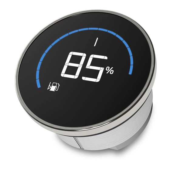
DISPLAY LAYOUT DISPLAY LAYOUT DISPLAY SECTIONS A: Round Bar Graph The bar graph helps to interpret the displayed vessel information quicker and more intuitive. The minimum and maximum values of the bar graph range are customizable via the VMH14 App. (Refer to the section Configurations to learn more about the process of customizing and the limitations of the bar graph ranges.) -
Page 11: Configuration
CONFIGURATION CONFIGURATION VMH 14 CONFIGURATOR APP To configure the VMH 14, some parameters must be calibrated, like which value to display, the range of the bar graph and the alarms such as their thresholds. This is possible through the smartphone App “VMH 14”, which can be downloaded free of charge from the stores of both Android and iOS devices. -
Page 12: Vmh 14 Configuration
CONFIGURATION VMH 14 CONFIGURATION READ THE VMH 14 CONFIGURATION Launch the “VMH 14” App and read the current configuration of the device by “tapping” the smartphone onto the NFC symbol on the devices rear side. The READ operation is mandatory before the WRITE operation is allowed. - Page 13 CONFIGURATION 4. BARGRAPH SETTINGS It’s possible to customize the range of values, which the bar graph should be able to reach. In order to do so, just move the levers into the desired position. 5. CONFIGURE THE ALARM The alarm can be activated or deactivated by using the switches on the right side of the according alarm description.
-
Page 14: Supported Configurations
CONFIGURATION SUPPORTED CONFIGURATIONS Gauge Type Symbol Unit Bar Graph Range 0 – 100 % Fuel Level Default: 0 – 100 % (Set as factory default) 0 – 100 % Trim TRIM Default: 0 – 100 % 0 – 200 °C °C Coolant Temperature Default: 40 –... -
Page 15: Technical Data
TECHNICAL DATA TECHNICAL DATA DATASHEET Nominal Voltage 12 V (from EasyLink connection) Connectivity EasyLink, NFC Configuration interface NFC (Near Field Communication) Protection class IP X7 acc. IEC60529 Optically bonded IBN segment display Display Mineral glass Lens Ø52 mm – Polycarbonate (PC), flame retardant acc. Housing UL94-V0 Required mounting depth... -
Page 16: Technical Drawings
TECHNICAL DATA TECHNICAL DRAWINGS B001225... -
Page 17: Accessories
ACCESSORIES ACCESSORIES Accessory Part Number EasyLink Extension cable A2C59500139 Spinlock Nut 52 mm A2C52059471 52 mm Rubber sealing gasket A2C53194838 Visit http://www.veratron.com for the complete list of accessories. B001225... - Page 18 • Copying contents without any modifications and stating Veratron AG as copyright owner. Veratron AG reserves the right to make modifications or improvements to the relative documentation without notice. Requests for authorization, additional copies of this manual or technical information on the latter, must be addressed to veratron...
Need help?
Do you have a question about the VMH Series and is the answer not in the manual?
Questions and answers