
Subscribe to Our Youtube Channel
Related Manuals for Veratron VIEWLINE A2C59512390


Summary of Contents for Veratron VIEWLINE A2C59512390
- Page 1 TIMELESS INSTRUMENTS VIEWLINE 85MM TACHOMETERS USER MANUAL rev. AA B001686...
-
Page 2: Table Of Contents
CONTENT CONTENT PART NUMBERS ..................3 Tachometers with LCD .................... 3 Tachometers without LCD ..................3 SAFETY INFORMATION ................. 4 Safety During Installation ..................4 Safety After Installation ................... 5 Electrical Connection ....................5 MECHANICAL INSTALLATION ............6 Before the Assembly ....................6 Installation with Spinlock .................. -
Page 3: Part Numbers
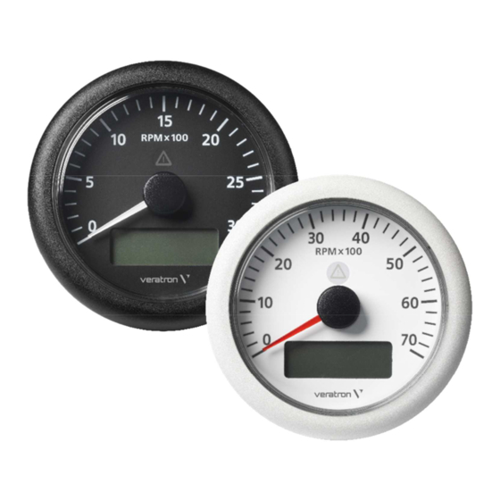
PART NUMBERS PART NUMBERS TACHOMETERS WITH LCD Part Number Dial Color Range Diameter A2C59512390 Black 3000 RPM 85 mm A2C59512396 White A2C59512391 Black 4000 RPM 85 mm A2C59512397 White A2C59512392 Black 5000 RPM 85 mm A2C59512398 White A2C59512393 Black 6000 RPM 85 mm A2C59512399 White... -
Page 4: Safety Information
• Use our product only as intended. Use of the • Modifications or manipulations to Veratron product for reasons other than its intended use products can affect safety. Consequently, you may lead to personal injury, property damage may not modify or manipulate the product! •... -
Page 5: Safety After Installation
SAFETY INFORMATION • The electrical indicator outputs and cables keyhole saws or files. Deburr edges. Follow the safety instructions of the tool manufacturer. connected to them must be protected from • Use only insulated tools, if work is necessary on direct contact and damage. -
Page 6: Mechanical Installation
MECHANICAL INSTALLATION MECHANICAL INSTALLATION WARNING Before beginning, disconnect the negative terminal on the battery, otherwise you risk a short circuit. If the vehicle is supplied by auxiliary batteries, you must also disconnect the negative terminals on these batteries! Short circuits can cause fires, battery explosions and damages to other electronic systems. Please note that when you disconnect the battery, all volatile electronic memories lose their input values and must be reprogrammed. -
Page 7: Installation With Spinlock
MECHANICAL INSTALLATION INSTALLATION WITH SPINLOCK Conventional assembly. (Instrument is put into the drill hole from the front). The panel thickness may be within a range of 2 to 18 mm. The drill hole must have a diameter of 81 to 86 mm. WARNING •... -
Page 8: Flush Mounting
MECHANICAL INSTALLATION FLUSH MOUNTING The recommended panel thickness is 1.5 to 3 mm. The drill hole must have a diameter of 75.4 mm. Ensure that the installation location is level and has no sharp edges. WARNING • Do not drill holes or ports in load-bearing or stabilizing stays or tie bars! •... -
Page 9: Installation With Brackets
MECHANICAL INSTALLATION INSTALLATION WITH BRACKETS Conventional assembly. (Instrument is put into the drill hole from the front). The panel width may be within a range of 2 to 13 mm. The drill hole must have a diameter of 81 mm. WARNING •... -
Page 10: Electrical Installation
ELECTRICAL INSTALLATION ELECTRICAL INSTALLATION WARNING • Refer to the safety rules described in the electrical connections section of the safety information chapter of this document! Depending on the configuration, insert the cable into the 8-pin and 14-pin contact enclosure according to the following pin assignment. -
Page 11: Connection Diagrams
ELECTRICAL INSTALLATION CONNECTION DIAGRAMS TACHOMETER WITH LCD Designations in the wiring diagrams: 30 – Term. 30 – steady-state plus 12 V 31 – Term. 31 - ground 15 – Term. 15 – connected (ignition) plus F1 – Fuse 5A quick-response 58 –... -
Page 12: Configuration With Lcd
CONFIGURATION WITH LCD CONFIGURATION WITH LCD BASICS Press the key briefly (< 2sec.) to change the currently displayed value. Press the key longer (> 2sec.) to change to the next value. The display returns to normal operating mode if a key is not pressed for 30 seconds. Any settings you have made are not saved. -
Page 13: Setting The Unit And Alarm Threshold
CONFIGURATION WITH LCD SETTING THE UNIT AND ALARM THRESHOLD 1. Activate T. 30 (8-pin - Pin1) 2. Deactivate T. 15 (8-pin - Pin4) 3. Press and hold Mode key (14-pin - Pin 12) 4. Activate T. 15 5. Release Mode key Press and hold Mode key. -
Page 14: Configuration Without Lcd
Ensure that switch position “1” points toward the center of the instrument. Select switch position “XXX” if you want to set an impulse number with the optional PC software. Please contact your Veratron partner for more information. Puls./Rev. Switch 1... -
Page 15: Lcd Operation
LCD OPERATION LCD OPERATION DISPLAY INDICATOR SELECTION 1. Activate T. 30 (8-pin - Pin1) 2. Activate T. 15 (8-pin - Pin4) Total operating hours Press Mode key briefly. Trip hours Press Mode key briefly. Clock Press Mode key briefly. On-board voltage SETTING THE BRIGHTNESS 1. -
Page 16: Resetting The Trip Counter
LCD OPERATION RESETTING THE TRIP COUNTER 1. Activate T. 30 (8-pin - Pin1) 2. Activate T. 15 (8-pin - Pin4) Press the Mode key repeatedly until the trip hours are displayed. Press and hold Mode key. Trip is now deleted. SETTING THE CLOCK 1. -
Page 17: Technical Data
TECHNICAL DATA TECHNICAL DATA Nominal Voltage 12 V / 24 V Operating Voltage 8 – 32 V with overvoltage and reverse polarity protection Current consumption < 175 mA with warning LED 0.5-399 Imp/U (Default: 6Imp/U) programmable via LCD or Pulse count range with optional PC Software. -
Page 18: Accessories
A2C5319291401 Bezel – Triangular, Black A2C5319291701 Bezel – Triangular, White A2C5319292001 Bezel – Triangular, Chrome A2C5319291801 Bezel – Flat, Black A2C5319291101 Bezel – Flat, White A2C5319291201 Bezel – Flat, Chrome A2C5319291001 Visit http://www.veratron.com for the complete list of accessories. B001686... - Page 19 Any distribution, translation or reproduction, partial or total, of the document is strictly prohibited unless with prior authorization in writing from Veratron AG, except for the following actions: • Printing the document in its original format, totally or partially.
Need help?
Do you have a question about the VIEWLINE A2C59512390 and is the answer not in the manual?
Questions and answers