Table of Contents
Advertisement
Quick Links
WCC 106 UL
Installation instruction
MotorController
(Version 2402)
Save this installation manual for the end user
The latest version of this document can always be found on our website
US
+1 215 699 9292 / +1 650 360 5414
Others
+45 45 670 300
WCC 106 UL install 2402 – US ©WindowMaster 2023, 2024 ®WindowMaster is a registered trademark used under license from WindowMaster International A/S
WindowMaster International A/S, Skelstedet 13, DK 2950 Vedbæk
info.us@windowmaster.com
info.dk@windowmaster.com
windowmaster.com
Advertisement
Table of Contents

Summary of Contents for Window Master WCC 106 UL
- Page 1 +1 215 699 9292 / +1 650 360 5414 info.us@windowmaster.com windowmaster.com Others +45 45 670 300 info.dk@windowmaster.com WCC 106 UL install 2402 – US ©WindowMaster 2023, 2024 ®WindowMaster is a registered trademark used under license from WindowMaster International A/S WindowMaster International A/S, Skelstedet 13, DK 2950 Vedbæk...
-
Page 2: Table Of Contents
1 Safety regulations ................................ 3 Safety ................................3 120V AC ................................3 Application ................................. 3 Cabling and electrical connection ........................3 2 Introduction to WCC 106 ............................. 3 The MotorController’s construction ........................3 Max number of actuators per MotorController....................... 4 3 Accessories .................................. -
Page 3: Safety Regulations
Safety regulations Safety Only allow correspondingly trained, qualified and skilled personnel to carry out installation work. Reliable operation and the avoidance of damage and hazards are only guaranteed if installation and settings are carried out carefully in accordance with these instructions. There may be personal danger by electrically operated windows: - the forces occurring in the automatic mode can be such that parts of the body could get crushed. -
Page 4: Max Number Of Actuators Per Motorcontroller
Max number of actuators per MotorController The table shows the maximum number of actuators which can be connected to the WCC 106. The total power consumption for all connected actuators incl. load on X7 (AUX max 0.5A) may not exceed 6A. Per motor line Per MotorController ®... -
Page 5: Technical Data
Technical data Technical data Output current 6A incl. load on X7 (max 0.5A) Secondary voltage Voltage 24V DC (±15%) Resting potential with 120V AC without load 24V DC @ 20°C Ripple with full load 200mVp-p 24V DC, 500mA Motor groups / Motor lines Up to 2 motor groups with each 1 motor line Either ±24V standard actuators or MotorLink®... -
Page 6: Connecting Cables In The Motorcontroller
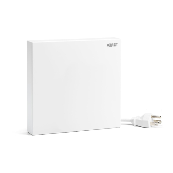
When routing cables, all applicable national regulations must be complied with. The MotorController is supplied with a 6' 6 ¾'' cable with US plug (type B). Connecting cables in the MotorController Cables are to be connected in accordance with the chapter “Connection plan for WCC 106”, the short chapters and other relevant paragraphs in these guidelines. -
Page 7: 7.1.2 Max. Cable Length - ±24V Standard Actuators
7.1.2 Max. cable length – ±24V standard actuators The actuator cable must have 2 wires minimum. ±24V standard actuators The PE wire/the green-yellow earth wire must not be used Cable- AWG 18 AWG 16 AWG 14 AWG 12 cross-section [a] (3-wire 0.82mm²) (3-wire 1.31mm²) (3-wire 2.08mm²) -
Page 8: Connection Plan For Wcc 106
Connection plan for WCC 106 The above connection plan shows a WCC 106 MotorController... -
Page 9: Connection Description
Connection description On the WCC 106 the following can be connected: ±24V standard actuators, MotorLink® actuators, comfort keypad, thermostat and similar plus wind / rain sensor. WCC 106 contains two motor lines to which ±24V standard actuators or MotorLink® actuators can be connected. - Page 10 may also be connected. The locking actuators’ power consumption is not included in the calculated 6A as the actuators and locking actuators do not run simultaneously. All actuators on the same motor line run/are operated at the same time. All actuators on a motor line must be the same type. Connection / cable diameter: flexible max AWG 10 / solid max AWG 8.
- Page 11 X2 / X4 Input for connection of comfort keypad Motor line 1: Motor line 2: Input circuit (simplified) Data: Data: 2.1 Open 4.1 Open 2.2 Close 4.2 Close 2.3 GND / 0V 4.3 GND / 0V With the factory-set values the input is: “Active”...
- Page 12 AUX, power supply for weather station, for example. See “X10” for a description of connection of rain/wind sensors. Data: 7.1 24V 7.2 0V Maximum 500 mA Main power must be switched off, before connecting any kind of external equipment to X7! Connected consumption must be included in the controller’s total load, which must not exceed 6A.
-
Page 13: Dip Switch Configuration
Reset FW update; to be used in line with firmware updates No function on this product version Yellow LED that indicates error on the MotorController. As a reference to fault output X9. LED 1 If the diode is off, there is no error/failure. Output X9 is OFF. See chapter, “Status and troubleshooting via LED on the MotorController”... -
Page 14: Status And Troubleshooting Via Led On The Motorcontroller
Status and troubleshooting via LED on the MotorController In the event of failure/error of the MotorController one or more diodes will light and/or blink. On the WCC 106 there are 4 diodes - 3 green and 1 yellow - that can indicate errors and status on the MotorController. Irrespective which diode lights or blinks, the indicator is based on a 3.2 second sequence that is repeated continuously. -
Page 15: Commissioning And Test Run
Green diode – LED 4 The green diode LED 4 (closest to X8) indicates status of or error on the motor line #1. Black = diode off Commissioning and test run In the event of error messages, refer to chapter “Status and troubleshooting via LED on the MotorController”. 12.1 MotorController fully installed, without operating power Check all mechanical and electrical components for damage.


Need help?
Do you have a question about the WCC 106 UL and is the answer not in the manual?
Questions and answers