Table of Contents
Advertisement
Quick Links
WCC 103 A
Installation instruction
MotorController
(Version 2311)
Save this installation manual for the end user
The latest version of this document can always be found on our website
UK
+44 1536 614070
Others
+45 45 670 300
WCC 103 A install 2311 – EN_DE_DK ©WindowMaster 2023 ®WindowMaster is a registered trademark used under license from WindowMaster International A/S
WindowMaster International A/S, Skelstedet 13, DK 2950 Vedbæk
info.uk@windowmaster.com
info.dk@windowmaster.com
www.windowmaster.com
Advertisement
Table of Contents

Related Manuals for Window Master WCC 103 A


Summary of Contents for Window Master WCC 103 A
- Page 1 +44 1536 614070 info.uk@windowmaster.com www.windowmaster.com Others +45 45 670 300 info.dk@windowmaster.com WCC 103 A install 2311 – EN_DE_DK ©WindowMaster 2023 ®WindowMaster is a registered trademark used under license from WindowMaster International A/S WindowMaster International A/S, Skelstedet 13, DK 2950 Vedbæk...
-
Page 2: Table Of Contents
Formula for calculating max. actuator cable length ..................7 Max. cable length – ±24V standard actuators ....................7 7.1.2 8 Connection plan for WCC 103 A ..........................7 9 Connection description ............................... 8 10 Control via remote control – WCA 100 ........................11 10.1... -
Page 3: Safety Regulations
Introduction to WCC 103 A WCC 103 A is a MotorController that controls (opens/closes) 1 or more ±24V standard window actuators on the basis of a signal from the remote-control type WCA 100, the app “Fresh Air Control”, connected comfort keypads or the connected components, e.g. -
Page 4: Motorcontroller Variants
The table shows the maximum number of actuators. Total power consumption for all connected actuators incl. load on X7 (AUX max 0.5A) may not exceed 3A. Only ±24V standard actuators may be connected to WCC 103 A. Actuator type Max number ± 24V actuators that may be connected to WCC 103 A WMD 820-1 WMD 820-2 WMD 820-3... -
Page 5: Accessories
Actuator type Max number ± 24V actuators that may be connected to WCC 103 A WMB 801/802 WMB 811 / 812 / 815 / 816 / 817 / 818* *with 2 locking actuators on the same motor line use: 1 x WMB 811 and 1 x WMB 812. 1 x WMB 815 and 1 x WMB 816 or 1 x WMB 817 and 1 x... -
Page 6: Mounting
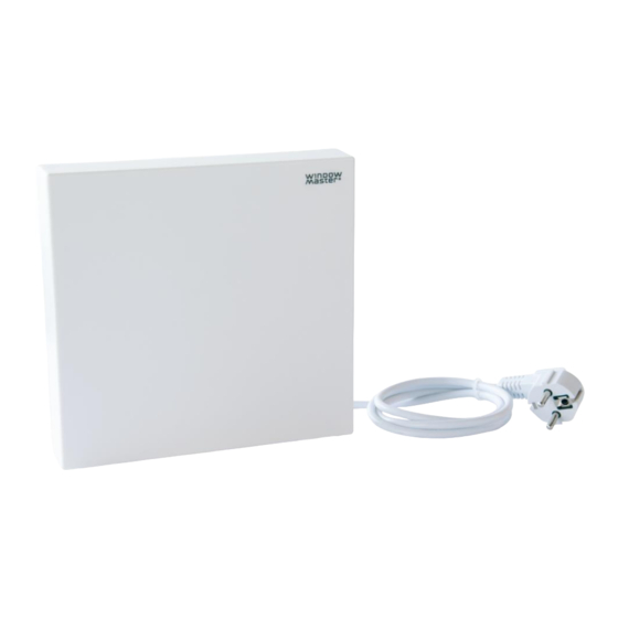
The MotorController is supplied with a 1.2 m cable with Schuko plug. Connecting cables in the MotorController Cables are to be connected in accordance with the chapter “Connection plan for WCC 103 A”, the short chapters and other relevant paragraphs in these guidelines. -
Page 7: Cable Dimensioning
1.50 mm² 1.50 mm² 2.50 mm² 2.50 mm² 4.00 mm² 2-wire 2-wire Total parallel parallel actuator current [l] 168m 140m 280m 224m 140m 112m Connection plan for WCC 103 A The above connection plan shows a WCC 103 A MotorController... -
Page 8: Connection Description
±24V standard actuators, comfort keypad, thermostat and similar plus wind / rain sensor. WCC 103 A contains one motor line to which only ±24V standard actuators can be connected. Data 1.1 24V / 0V 1.3 0V / 24V The number of permitted actuators on the motor line depends on the actuator type. - Page 9 Standard actuators Connecting variants to standard actuators on motor line 1 ±24V Example with max. 3A current consumption a) 3 pcs. WMX 826-1 b) 2 sets of 3 pcs. WMX 504-3 c) 1 pc. WMU 883-1 d) 2 pcs. WMU 861-2 Input for connection of comfort keypad Input circuit (simplified) Data:...
- Page 10 Connecting wind / rain sensors of type WLA 330 or WLA 331. Wind / rain sensor must be connected on both X10 and X7. Data: Input circuit (simplified) 10.1 Common Open 10.2 Common Close (Rain) 10.3 GND / 0V X10 has highest priority over X2 and X3. With the factory-set values the input is: “Active”...
-
Page 11: Control Via Remote Control - Wca 100
The remote control has 3 buttons, each with 3 keys (functions) – OPEN, STOP and CLOSE. However, when paired with the WCC 103 A, it is only the top and bottom button which are working, meaning the middle button does not have any function. -
Page 12: Control Via App - Fresh Air Control
In the event of failure/error of the MotorController one or more diodes will light and/or blink. On the WCC 103 A there are 3 diodes - 2 green and 1 yellow - that can indicate errors on the MotorController. Irrespective which diode lights or blinks, the indicator is based on a 3.2 second sequence that is repeated continuously. Each sequence is defined by 32 x 0.1 second time segments. -
Page 13: Commissioning And Test Run
If commissioning proceeds correctly, the lid of the MotorController may be fitted. If commissioning does not proceed correctly, i.e., there is an error in one of the test points, refer to chapter “Connection description” If necessary, re-test the cable routing in accordance with chapter “Connection plan for WCC 103 A”. Maintenance Control and maintenance should only be done by the manufacturer or an authorized partner.
Need help?
Do you have a question about the WCC 103 A and is the answer not in the manual?
Questions and answers