Advertisement
Quick Links
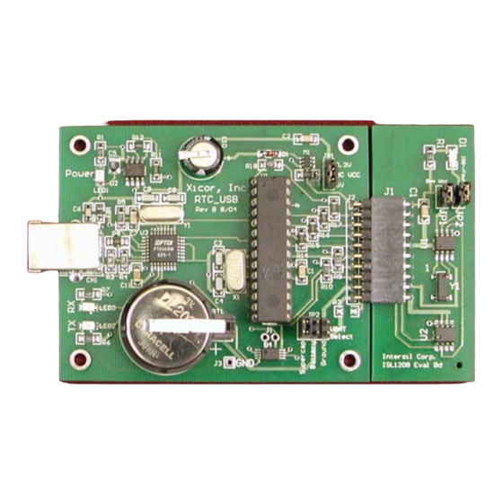
Real Time Clock USB Evaluation Board
This evaluation board provides a platform for testing the
ISL1208 and ISL1209 Real Time Clock (RTC) devices.
Device features include a crystal oscillator, clock and date
counters, and an alarm. The ISL1209 device includes an
event-detection feature for recording the time of an event.
The evaluation board provides a platform to test all of these
functions, as well as evaluate device performance criteria,
such as long-term clock accuracy. Hardware options such as
battery and crystal types can also be tested. The software is
designed to allow easy setup and monitoring of all major
device functions. The two-piece construction utilizing a
motherboard and a daughtercard enables the board and
software to operate the RTC device residing on a remote
board.
FIGURE 1.
Operation of the RTC Evaluation Board
Hookup and Power
CONNECTIONS
The eval board consists of a motherboard and daughtercard
and these need to be connected together. The evaluation
board uses hardware and software from FTDI for USB
communications and these drivers must be installed on each
PC that talks to the RTC eval board. A USB cable, with type
A and B connectors on the ends, is required to hook up the
board to a PC. The cable should be connected to the PC first
and then to the eval board. Once connected, LED1 will
illuminate indicating +5V power is available from the USB
cable.
POWERING DOWN
The daughter card contains backup power, consisting of a
battery or supercap. When powering down, the
daughtercard will operate off the backup source determined
by JP2 (after the V
voltage discharges from the V
CC
supply capacitors). If the user wishes to totally power down
the RTC device once V
is removed, then either remove
CC
AN1176 Rev 0.00
Jun 20, 2005
the daughtercard from the motherboard or set JP2 to GND.
Keep in mind there is a decoupling capacitor on the
daughtercard (0.1µF) which must discharge fully before the
RTC device stops operating. This discharge time can be up
to one second when using a V
powered down, the RTC board cannot be monitored by the
RTC software.
Installing the RTC Software and USB Drivers
USB DRIVERS AND COM PORT SETUP
Insert the Intersil RTC_USB CDROM in the PC to be used.
Open the folder "Install USB". Then open the ZIP file
"FTDI.zip". Extract this set of files to a separate folder on
your main hard drive. For example, create a folder titled
"FTDI" on your C: drive, then extract the contents of the ZIP
file to that folder. In the "Install USB" folder, there is a pdf file
titled "Windows Drivers Installation Guide". Open that file
and follow the instructions for the FTDI 232 device (you will
need to connect the RTC_USB Eval Board to your PC's USB
port, this will bring up a prompt to install the USB hardware
and software drivers).
Note that both a hardware AND a software driver need to be
installed for correct USB operation. These are two
procedures that are best done sequentially per the FTDI
Installation Guide.
Once the USB drivers are loaded, locate the RTC program,
titled "Intersil 12xx_2.exe" on the CD. This program can be
placed anywhere on the PC, or may be run from the CD.
Double-click to execute the program (note that the ".._2"
may be changed as the program is updated and the revision
changes).
After starting the program, an error window may appear
indicating that a certain COM port is not available. Dismiss
this window by clicking "OK". A timeout error may follow and
this should be dismissed as well.
On the Intersil RTC Data Analyzer main window, click on the
"Setup" pulldown menu. Click on "Autodetect" and the
program will search each COM port to find which is
connected to the USB device on the eval board. A small
"COM Auto Detect" window will appear and monitor the
polling process. Once the correct COM port is detected, it is
noted in the "COM Auto Detect" window and that window will
close. If you wish to review which COM port is being used,
just click again on the "Setup" pulldown menu.
If no COM port is detected, make sure the board is
connected to the PC with a USB cable and that the board
jumpers are in the appropriate places (see hardware
CC
section). If there is still no COM port detected after any
USER'S MANUAL
Jun 20, 2005
of 5V. Note that when
CC
Page 1 of 11
AN1176
Rev 0.00
Advertisement

Related Manuals for Renesas ISL1208


Summary of Contents for Renesas ISL1208
- Page 1 This evaluation board provides a platform for testing the the daughtercard from the motherboard or set JP2 to GND. ISL1208 and ISL1209 Real Time Clock (RTC) devices. Keep in mind there is a decoupling capacitor on the Device features include a crystal oscillator, clock and date daughtercard (0.1µF) which must discharge fully before the...
- Page 2 corrections, see the troubleshooting section at the end of this Modifying RTC Registers document. Open the RTC Register screen using the shortcut key in the menu bar (the group of 1s and 0s). The RTC Registers are If the COM port number is known in advance (it may be located available using the pulldown menu on the left.
- Page 3 CLEAR EVENT Temperature Compensation Compensation for crystal frequency variation over temperature Resets the EVT bit to “0”. The Event Input will ignore any is accomplished using the Temperature Compensation activity on the Event Input pin while the EVT bit is set to 1. Settings window.
- Page 4 room temperature when V is set to 5V. There is also a removal or replacement for development activity and software CR2032 battery included in a socket to allow removal/ upgrades with a newly-programmed device. replacement without soldering. This battery will last up to ten DAUGHTERCARD CONNECTOR (J3) years in normal backup operation.
- Page 5 OPEN DRAIN OUTPUT The ISL1209 daughtercard contains the ISL1209 device, crystal, decoupling capacitor, temp-sensor, and an LED (D1), The open drain output of the ISL1208 is the IRQ-F signal. for monitoring the open drain output, similar to the ISL1208 There is a jumper (JP2) which connects D1 when a shunt is in daughtercard.
-
Page 6: Troubleshooting
EVENT INPUT CONTROL BLOCK EVENT INPUT SWITCH EVENT INPUT (ALTERNATIVE) FIGURE 5. ISL1209 DAUGHTERCARD EVENT INPUT, J2 Using the Autodetect function in the setup menu will usually do this automatically for you. This can be used as a separate input for event detection. If the Also note that the serial USB drivers will only work on WIN98, connections on J3 are left open, then a normally closed switch WIN2000, and EXP machines. - Page 7 An ammeter can be Suggested RTC Tests connected between the terminals of the backup source and ISL1208 or ISL1209 the V input on JP2 of the motherboard. Only one source may be selected at a time, so the shunt needs to be 1.
- Page 8 2. Once the software is running, all functions available on the Using the RTC-USB Motherboard with Older eval board can be used. Note that there is no temp sensor X1227 Daughtercards on the X1227 daughtercard, so there is no temp monitoring The RTC-USB board is compatible with and can be used with available.
- Page 9 RTC Motherboard Bill of Materials (Continued) DESIGNATOR PART TYPE FOOTPRINT DESCRIPTION PART # PART NUMBER LED1 RED SM LED 1206 LED Red Low Current LED Lumex SML-LX23IC-TR Surface Mount LED2 GREEN SM 1206 LED Green Low Current Lumex SML-LX23GC-TR LED Surface Mount LED3 YELLOW SM 1206 LED...
- Page 10 ISL1208 Bill of Materials DESIGNATOR PART TYPE FOOTPRINT DESCRIPTION MFR PART NUMBER PART NUMBER 0.1µF 1206 Capacitor 1206 Resistor CON10 CONN_10_A Connector Samtec SSQ-110-02-S-S-RA HEADER 2 CONN2 Molex 0.1" 2-pin header HEADER 2 CONN2 Molex 0.1" 2-pin header LM76 LSOIC8...
-
Page 11: Sales Offices
10. It is the responsibility of the buyer or distributor of Renesas Electronics products, or any other party who distributes, disposes of, or otherwise sells or transfers the product to a third party, to notify such third party in advance of the contents and conditions set forth in this document.
Need help?
Do you have a question about the ISL1208 and is the answer not in the manual?
Questions and answers