Advertisement
Quick Links
ISL59482EVAL1Z
Evaluation Board User Guide
Introduction
The ISL5948xEVAL1Z evaluation board contains the
ISL59482 Dual 4:1 RGB MUX amp and associated
components needed to implement an 8:1 RGB+H/V sync
video multiplexer. The 8 video input ports, and single output
port are accessed using standard 15 pin VGA female
connectors. The I/O connectors are compatible with most
VGA, SVGA and XGA video sources and video monitors with
VGA cable interfaces. A typical application would use the
ISL5948xEVAL1Z board to multiplex anywhere from 2 to 8
PC's or laptops to a single video monitor or projector.
Evaluation Board Description and Key Features
The multiplexing of the RGB video is performed by the
ISL59482. Multiplexing the H and V sync signals is
accomplished using two ISL84051 8:1 analog switches. The
ISL59482 Video MUX and the analog H and V sync
multiplexers have the same input channel select logic
coding, and are parallel-connected to form a single 3 input
binary coded interface (S0, S1, S2). An additional ISL84051
8:1 analog switch and channel-select LED indicators are
included to identify the selected input channel. The
evaluation board contains three different channel select
options via jumpers on the board. Switches on the board
enable direct logic control in binary format. The on-board
oscillator and 4-bit counter can be connected to provide a
Evaluation Board Jumper, Cable Header, and Switch Descriptions
COMPONENT
JUMPERS
J1
Selects channel select via single-step momentary contact switch S4, or auto mode using on-board oscillator
J-S0
Selects S0 logic input to manual control via switch S0 or through external control ribbon cable header
J-S1
Selects S1 logic input to manual control via switch S1 or through external control ribbon cable header
J-S2
Selects S2 logic input to manual control via switch S2 or through external control ribbon cable header
HEADERS
EN
External MUX enable: Internal pull-down (logic 0) enables RGB+H/V output, logic high disables RGB and H/V sync output
S0
External S0 channel select logic input
S1
External S1 channel select logic input
S2
External S2 channel select logic input
SWITCHES
S0
Manual channel select logic input S0
S1
Manual channel select logic input S1
S2
Manual channel select logic input S2
S3
Momentary contact channel select step control
AN1282 Rev 0.00
January 10, 2007
USER'S MANUAL
continuous channel-by-channel scan of as few as 2 input
channels up to all 8 (Table 2). A jumper option allows the
user to disconnect the auto-scan oscillator and use the on-
board momentary-contact switch to manually scan through
the selected channels.
Reference Documents
• ISL59482 Data Sheet, FN6209
Getting Started
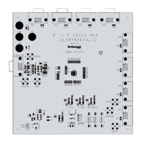
The evaluation board should have the same appearance as
the silk screen shown in Figure 1. Prior to applying power,
connect the source input VGA cables and the evaluation
board output VGA cable to the respective video
components. The evaluation board, as supplied, is designed
for 75 source impedances and requires a 75 termination
impedance in the output display device.
Applying Power to the Evaluation Board
The following safeguards will ensure correct power-up.
1. Limit the current on ±5V supplies to 250mA.
2. Turn on the power supplies after the power cables are
attached to the evaluation board.
Power supply protection Schottky diodes are included on the
±5V supplies to prevent damage due to reverse polarity.
DESCRIPTION
AN1282
Rev 0.00
January 10, 2007
Page 1 of 8
Advertisement

Related Manuals for Renesas ISL59482EVAL1Z


Summary of Contents for Renesas ISL59482EVAL1Z
- Page 1 USER’S MANUAL ISL59482EVAL1Z AN1282 Evaluation Board User Guide Rev 0.00 January 10, 2007 continuous channel-by-channel scan of as few as 2 input Introduction channels up to all 8 (Table 2). A jumper option allows the The ISL5948xEVAL1Z evaluation board contains the...
- Page 2 ISL59482EVAL1Z FIGURE 1. ISL5948xEVAL1Z TOP VIEW AN1282 Rev 0.00 Page 2 of 8 January 10, 2007...
- Page 3 ISL59482EVAL1Z Auto-Scan Test Testing the Evaluation Board 1. Connect scope probe to the J1 AUTO pin and observe a Testing the video and sync signal paths is accomplished logic level (0 to +5V) square wave with ~3s period. using 1 or more RGB+H/V test video sources and a video 2.
-
Page 4: Video Out
ISL59482EVAL1Z Internal and External Channel Select Logic TABLE 1. CHANNEL SELECT TRUTH TABLE J-S0, J-S1 and J-S2 are two-position jumpers that control the VIDEO OUT method of channel selection. In the AUTO position, the internal channel scan is enabled. The MANUAL position connects the on-board SPDT switches (S0, S1, and S2) for manual selection. -
Page 5: Switch Position
ISL59482EVAL1Z TABLE 2. CHANNEL SCAN SELECT LOGIC TABLE JUMPER POSITION SWITCH POSITION CHANNELS SELECTED CHANNELS SCANNED J-S2 J-S1 J-S0 Auto Auto Auto Manual Auto Auto Manual Auto Auto Auto Manual Auto Auto Manual Auto Auto Auto Manual Auto Auto Manual... - Page 6 ISL59482EVAL1Z ISL5948xEVAL1Z Schematic Diagram AN1282 Rev 0.00 Page 6 of 8 January 10, 2007...
- Page 7 ISL59482EVAL1Z ISL5948xEVAL1Z Components List COMPONENT P/N, VALUE MANUFACTURER RATING ISL5948xEVAL1Z REV A PCB, ROHS Intersil Corp. - 8:1 RGB Video MUX ISL59482IRZA QFN48 Pb-Free Intersil Corp. - 8:1 Analog MUX ISL84051IBZ SOIC16 Pb-Free Intersil Corp. - Hex Inverter SN74HC14D SOIC14...
-
Page 8: Sales Offices
10. It is the responsibility of the buyer or distributor of Renesas Electronics products, or any other party who distributes, disposes of, or otherwise sells or transfers the product to a third party, to notify such third party in advance of the contents and conditions set forth in this document. - Page 9 Mouser Electronics Authorized Distributor Click to View Pricing, Inventory, Delivery & Lifecycle Information: Renesas Electronics ISL59482EVAL1Z...
Need help?
Do you have a question about the ISL59482EVAL1Z and is the answer not in the manual?
Questions and answers