Table of Contents
Advertisement
Quick Links
KW45B41Z-LOCUM
KW45B41Z-LOC Board User Manual
Rev. 1 — 23 November 2023
Document Information
Information
Keywords
Abstract
Content
KW45B41Z-LOCUM, KW45B41Z-LOC, KW45B41Z, Bluetooth LE 5.3, CAN FD
The KW45B41Z-LOC board is a highly configurable, low-power, cost-effective evaluation and
development platform for NXPKW45B41Z MCU.
User manual
Advertisement
Table of Contents

Subscribe to Our Youtube Channel
Related Manuals for NXP Semiconductors KW45B41Z-LOCUM


Summary of Contents for NXP Semiconductors KW45B41Z-LOCUM
- Page 1 KW45B41Z-LOC Board User Manual Rev. 1 — 23 November 2023 User manual Document Information Information Content Keywords KW45B41Z-LOCUM, KW45B41Z-LOC, KW45B41Z, Bluetooth LE 5.3, CAN FD Abstract The KW45B41Z-LOC board is a highly configurable, low-power, cost-effective evaluation and development platform for NXPKW45B41Z MCU.
-
Page 2: Kw45B41Z-Loc Overview
KW45B41Z-LOCUM NXP Semiconductors KW45B41Z-LOC Board User Manual 1 KW45B41Z-LOC Overview The KW45B41Z-LOC board is a highly configurable, low-power, cost-effective evaluation and development platform for NXP KW45B41Z MCU, which is a low-power, highly secure, single chip wireless MCU based on Arm Cortex-M33 core. It offers an easy-to-use user interface with a virtual serial port and standard programming and run-control capabilities. -
Page 3: Board Features
KW45B41Z-LOCUM NXP Semiconductors KW45B41Z-LOC Board User Manual CR2032 I/O header mikroBUS 12 V 32.768 MH 5 V LDO 3V3 LDO QSPI U.FL UART MCU-Link micro-B Antenna RF line + GPIO KW45B 41Z switch JTAG Antenna 48HVQFN U.FL Auto qualified Reset... -
Page 4: Board Pictures
KW45B41Z-LOCUM NXP Semiconductors KW45B41Z-LOC Board User Manual Table 1. KW45B41Z-LOC features ...continued Board feature Target MCU feature used Description mikroBUS mikroBUS socket with two 1x8 position receptacles MCU-Link USB USB 2.0 micro-B connector for creating MCU-Link high- speed USB connection to the host computer, and providing 5... -
Page 5: Connectors
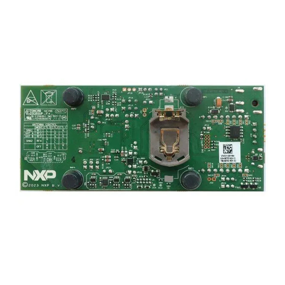
KW45B41Z-LOCUM NXP Semiconductors KW45B41Z-LOC Board User Manual Figure 3 shows the top-side view of the KW45B41Z-LOC board with jumpers highlighted. JP13 JP21 JP18 JP14 JP10 JP24 JP23 JP12 JP17 JP25 JP11 JP16 JP22 Figure 3. KW45B41Z-LOC jumpers Figure 4 shows the bottom-side view of the KW45B41Z-LOC board with battery holder (BT2) highlighted. -
Page 6: Jumpers
KW45B41Z-LOCUM NXP Semiconductors KW45B41Z-LOC Board User Manual Table 2. KW45B41Z-LOC connectors Part identifiers Connector type Description Reference section BT1 (DNP) Coin cell battery holders Holder for 3 V CR2450N lithium coin cell battery Section 2.1 (secondary option) Note: • BT1 and BT2 have... - Page 7 KW45B41Z-LOCUM NXP Semiconductors KW45B41Z-LOC Board User Manual Table 3. KW45B41Z-LOC jumpers ...continued Part identifier Jumper type Description Reference section Note: In the KW45B41Z-LOC board, P_VDD_SWITCH supply produces through jumper JP1 the target MCU supply VDD_SWITCH, which powers rest of the target MCU supplies.
- Page 8 KW45B41Z-LOCUM NXP Semiconductors KW45B41Z-LOC Board User Manual Table 3. KW45B41Z-LOC jumpers ...continued Part identifier Jumper type Description Reference section • Shorted (default setting): VDD_IO_ABC power is supplied to the target MCU 1x2 pin header VDD_ANA power enable jumper: • Open: VDD_ANA power is OFF •...
- Page 9 KW45B41Z-LOCUM NXP Semiconductors KW45B41Z-LOC Board User Manual Table 3. KW45B41Z-LOC jumpers ...continued Part identifier Jumper type Description Reference section • Shorted: The USB-to-UART bridge between MCU- Link and the target MCU is disabled JP12 1x2 pin header MCU-Link (LPC55S69) boot configuration jumper:...
-
Page 10: Push Buttons
KW45B41Z-LOCUM NXP Semiconductors KW45B41Z-LOC Board User Manual 1.7 Push buttons Table 4 describes the push buttons of the KW45B41Z-LOC board. Table 4. KW45B41Z-LOC push buttons Part identifier Name Description Reset button Pressing SW1 resets the target MCU (KW45B41Z) which causes board peripherals to reset to their default states and executes the boot code. -
Page 11: Kw45B41Z-Loc Functional Description
KW45B41Z-LOCUM NXP Semiconductors KW45B41Z-LOC Board User Manual Table 5. KW45B41Z-LOC LEDs Part identifier Color LED name/function Description LED1 User LED Controlled through a user application LED2 Yellow User LED Controlled through a user application LED3 Green Power-on indicator LED Indicates system power-on status. When the board is powered up, LED3 turns ON. -
Page 12: Power Supplies
KW45B41Z-LOCUM NXP Semiconductors KW45B41Z-LOC Board User Manual Note: For details of the KW45B41Z MCU features, see KW45B41Z Reference Manual. The chapter is divided into the following sections: • Section 2.1 "Power supplies" • Section 2.2 "Clocks" • Section 2.3 "CAN interface"... - Page 13 KW45B41Z-LOCUM NXP Semiconductors KW45B41Z-LOC Board User Manual COIN CELL P5V_CAN S E CONDARY HOLDER OPTION P3V3_LDO VBAT RB160M-30 NCP1117ST33T3G P3V3_BATT P3V3_BATT V_LDO_OUT VOUT RB160M-30 10uF SMTU2450N-LF S8421-45R RB160M-30 10uF 10UF FL_US B_5V0 FL_US B_5V0 MICRO B 330 OHM RB160M-30 TP21...
- Page 14 KW45B41Z-LOCUM NXP Semiconductors KW45B41Z-LOC Board User Manual Table 6. KW45B41Z-LOC power supplies ...continued Power source Manufacturing part Power supply rail Description number LDO voltage regulator NCP1117ST50T3G P5V_CAN (5 V) • Another power supply used to produce P5V supply (onsemi) • Supplies power to CAN transceiver U19 (TJA1057GT/3) •...
-
Page 15: Power Modes
KW45B41Z-LOCUM NXP Semiconductors KW45B41Z-LOC Board User Manual Table 6. KW45B41Z-LOC power supplies ...continued Power source Manufacturing part Power supply rail Description number is produced in DC-DC inductor circuit) • Supplies VDD_DCDC power to the target MCU From VDD_REG supply VDD_DCDC through jumper JP7 •... -
Page 16: Dc-Dc Inductor Options
KW45B41Z-LOCUM NXP Semiconductors KW45B41Z-LOC Board User Manual Table 8 shows the KW45B41Z-LOC board power supplies that support current measurement along with the jumpers that control these power supplies. All the jumpers, except the jumper JP2 are 2-pin jumpers and an ammeter is connected to both 1 and 2 pins of... -
Page 17: Clocks
KW45B41Z-LOCUM NXP Semiconductors KW45B41Z-LOC Board User Manual Figure 9 shows other possible inductor options. Automotive Maximum Isat Temperature Size Value Inductor type Manufacturer Part number qualified DC current (Ω) (mA) range (°C) (LxWxH) mm AEC-Q200 (mA) SMD shielded 1 μH MLZ2012A1R0WTD25 0.13... -
Page 18: Can Interface
KW45B41Z-LOCUM NXP Semiconductors KW45B41Z-LOC Board User Manual XTAL_32M XTAL_RF EXTAL_32M EXTAL_RF 32MHz NX1612S A 32MHZ EXS 00A CS 14160 Figure 10. 32 MHz clock circuit diagram Figure 11 shows the circuit diagram of the Y2 crystal that provides 32.768 kHz clock. Internal load capacitors provide the crystal load capacitance. -
Page 19: Lpuart Interface
KW45B41Z-LOCUM NXP Semiconductors KW45B41Z-LOC Board User Manual Table 10 explains the KW45B41Z-LOC CAN connections. Table 10. KW45B41Z-LOC CAN connections CAN module Voltage translators Transceiver Connector CAN0 Two voltage translators U17 High-speed CAN transceiver 1x4 pin CAN header J10. It allows external and U20 (74LVCH1T45). -
Page 20: Lpspi Interface
KW45B41Z-LOCUM NXP Semiconductors KW45B41Z-LOC Board User Manual Target MCU mikroBUS socket LPUART0 connector J2 Debugger MCU Voltage LPUART1 MCU-Link translator KW45B41Z Figure 14. LPUART diagram Table 11 explains the KW45B41Z-LOC LPUART connections. Table 11. KW45B41Z-LOC LPUART connections LPUART module Voltage translator Connector / MCU-Link LPUART0 mikroBUS socket connector J2. - Page 21 KW45B41Z-LOCUM NXP Semiconductors KW45B41Z-LOC Board User Manual Slave SPI NOR flash memory Master PCS0 LPSPI1 Slave mikroBUS socket connector J1 KW45B41Z Figure 15. LPSPI diagram Table 12 explains the KW45B41Z-LOC LPSPI connections. Table 12. KW45B41Z-LOC LPSPI connections Slave device PCS0 16 Mbit (2 MB) SPI NOR flash memory U5 (AT25XE161D-MAHN-T) for over-the-air (OTA) programming or for storing non-volatile system data or parameters mikroBUS socket connector J1.
-
Page 22: Lpi2C Interface
KW45B41Z-LOCUM NXP Semiconductors KW45B41Z-LOC Board User Manual 2.6 LPI2C interface The target MCU (KW45B41Z) has two low-power inter-integrated circuit (LPI2C) modules, LPI2C0 and LPI2C1. The KW45B41Z-LOC board only supports LPI2C1 module. Figure 17 shows the KW45B41Z-LOC LPI2C diagram. mikroBUS socket... - Page 23 KW45B41Z-LOCUM NXP Semiconductors KW45B41Z-LOC Board User Manual U.FL connector Antenna A 2.4 GHz radio RF switch Antenna B KW45B41Z Control signals U.FL connector Figure 18. RF diagram Figure 19 shows the KW45B41Z-LOC RF circuit diagram. VDD_P A_2G4 e na ble +10dBm RF output...
-
Page 24: Mikrobus Socket
KW45B41Z-LOCUM NXP Semiconductors KW45B41Z-LOC Board User Manual Table 14. RF I/O port selection ...continued Control signals RF mode RF I/O port CTRL3 CTRL2 CTRL1 High High All OFF None High High The KW45B41Z-LOC board supports programmable output power from -30 dBm to +10 dBm at the U.FL connectors. -
Page 25: Gpos
KW45B41Z-LOCUM NXP Semiconductors KW45B41Z-LOC Board User Manual MikroElektronika (MIKROE) is one of the manufactures of click boards. The details of few example click boards for KW45B41Z-LOC mikroBUS socket are available at MIKROE website. 2.9 GPOs Table 16 describes the target MCU pins that are used as general-purpose outputs (GPOs) on the KW45B41Z- LOC board. -
Page 26: Using Mcu-Link With Development Tools
KW45B41Z-LOCUM NXP Semiconductors KW45B41Z-LOC Board User Manual • Other firmware options available for MCU-Link OB may not provide the buffer enable / direction control support that is required to correctly configure the KW45B41Z-LOC hardware. Therefore, care should be taken while using such firmware. -
Page 27: Supported Mcu-Link Features
KW45B41Z-LOCUM NXP Semiconductors KW45B41Z-LOC Board User Manual 3. Follow the instructions in the readme.txt to find and run the firmware update utilities for CMSIS-DAP or J- Link versions. 4. Disconnect the board from the host computer, open jumper JP12, and reconnect the board. -
Page 28: Connecting To A Target Through A Usb-To-Uart Bridge
KW45B41Z-LOCUM NXP Semiconductors KW45B41Z-LOC Board User Manual Table 18. Supported debug scenarios ...continued Debug scenario Feature support Use MCU-Link as debugger for an • SWD: external target MCU – MCU-Link SWD feature is enabled (MCU-Link SWD disable jumper JP22 is open) –... -
Page 29: Software Support
KW45B41Z-LOCUM NXP Semiconductors KW45B41Z-LOC Board User Manual MLINK_3V3 P IO0_5-IS P _EN-LED_S WD_ACT S WD Activity Figure 20. MCU-Link status LED 4 Software support This section describes the software support for the KW45B41Z-LOC board. NXP provides a software development kit (SDK) for KW45B41Z-LOC board with several application examples. - Page 30 KW45B41Z-LOCUM NXP Semiconductors KW45B41Z-LOC Board User Manual Figure 22. NXP SDK software tag version 5. Press the Build MCUXpresso SDK button. Figure 23. NXP SDK and localization release build selection for given board 6. Select the highlighted preferences as shown in Figure Figure 24. SDK builder settings...
-
Page 31: Kw45B41Z-Loc Sdk Application Zip Package Structure
KW45B41Z-LOCUM NXP Semiconductors KW45B41Z-LOC Board User Manual 8. Press the Download SDK button. 4.2 KW45B41Z-LOC SDK application ZIP package structure Figure 25 shows the folder structure of the SDK ZIP package. Figure 25. SDK zip package folder structure Application related files are located at boards\kw45b41zloc\wireless_examples. -
Page 32: Programing Wireless Ranging Demo Application To Kw45B41Z-Loc Board
KW45B41Z-LOCUM NXP Semiconductors KW45B41Z-LOC Board User Manual Table 20. Required tools ...continued Tool Description MCUXpresso IDE Download the MCUXpresso Integrated Development Environment software from NXP website. 4.4 Programing Wireless Ranging demo application to KW45B41Z-LOC board To program the Wireless Ranging demo application to the KW45B41Z-LOC board, perform the following steps: 1. -
Page 33: Acronyms
KW45B41Z-LOCUM NXP Semiconductors KW45B41Z-LOC Board User Manual Table 21. Related documentation ...continued Document Description Link / how to access KW45B41Z-LOC RF Test Report Describes the KW45B41Z-LOC board RF Contact NXP FAE / sales performance representative Antenna Diversity Board User's Provides information about enabling the antenna... -
Page 34: Revision History
KW45B41Z-LOCUM NXP Semiconductors KW45B41Z-LOC Board User Manual Table 22. Acronyms ...continued Acronym Description SP4T Single-pole four-throw Serial peripheral interface Serial wire debug Serial wire debug trace output TCXO Temperature compensated crystal oscillator UART Universal asynchronous receiver/transmitter Universal serial bus VCOM Virtual communication... -
Page 35: Legal Information
NXP Semiconductors. In no event shall NXP Semiconductors be liable for any indirect, incidental, Translations — A non-English (translated) version of a document, including punitive, special or consequential damages (including - without limitation - the legal information in that document, is for reference only. -
Page 36: Table Of Contents
Please be aware that important notices concerning this document and the product(s) described herein, have been included in section 'Legal information'. © 2023 NXP B.V. All rights reserved. For more information, please visit: http://www.nxp.com Date of release: 23 November 2023 Document identifier: KW45B41Z-LOCUM...
Need help?
Do you have a question about the KW45B41Z-LOCUM and is the answer not in the manual?
Questions and answers