Table of Contents
Advertisement
Quick Links
Instructions - Parts
DV Series
Dispense Valves
Dispense valves for controlling material flow of adhesives, sealants, and other materials
that are compatible with the wetted parts of the valve. For professional use only.
Not approved for use in explosive atmosphere locations.
Important Safety Instructions
Read all warnings and instructions in
this manual. Save these instructions.
V1M320
Electric Heat, 3/4 in. npt Dispense Valve
V1M350
Ambient/Temperature Conditioning, 3/4 in. npt Dispense Valve
5000 psi (35 MPa, 345 bar) Maximum Working Pressure
See page 6 for models and approvals.
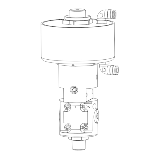
3A1792A
V1M350 Shown
r_v1m350_3a0412a_3a
ENG
Advertisement
Table of Contents

Related Manuals for Graco DV Series


Summary of Contents for Graco DV Series
- Page 1 Instructions - Parts DV Series Dispense Valves 3A1792A Dispense valves for controlling material flow of adhesives, sealants, and other materials that are compatible with the wetted parts of the valve. For professional use only. Not approved for use in explosive atmosphere locations.
-
Page 2: Table Of Contents
Technical Data ..... 29 Graco Standard Warranty ... . 32... -
Page 3: Warnings
Warnings Warnings The following warnings are for the setup, use, grounding, maintenance, and repair of this equip- ment. The exclamation point symbol alerts you to a general warning and the hazard symbols refer to procedure-specific risks. When these symbols appear in the body of this manual, refer back to these Warnings. - Page 4 Warnings WARNING WARNING WARNING WARNING FIRE AND EXPLOSION HAZARD Flammable fumes, such as solvent and paint fumes, in work area can ignite or explode. To help prevent fire and explosion: Use equipment only in well ventilated area. • Eliminate all ignition sources; such as pilot lights, cigarettes, portable electric lamps, •...
- Page 5 Warnings WARNING WARNING WARNING WARNING EQUIPMENT MISUSE HAZARD Misuse can cause death or serious injury. Do not operate the unit when fatigued or under the influence of drugs or alcohol. • Do not exceed the maximum working pressure or temperature rating of the lowest •...
-
Page 6: Models
Models Models 3/4 in. npt Dispense Valve Third Digit Fourth Digit Fifth Digit Sixth First and Digit Second Stroke Digit Type Air Open /Air Close Adjustment Heat 2 Electric Heat Ball / No Spring Adjustable Ambient/Temperature Seat Conditioning ETL Approved. †... -
Page 7: Component Identification
Component Identification Component Identification Electric Heated Valve Ambient/Temperature Conditioning Valve S, T, U, V r_v1m350_3a0412a_05a J, K J, K r_v1m350_3a0412a_03a . 1: 3/4 in. npt Dispense Valve - Typical Components Key: A Air Connections N Pressure Transducer Accessory Port (back B Air Section side of valve) C Travel Adjuster... -
Page 8: Theory Of Operation
The fluid outlet port dispenses material through a dis- pense nozzle in regulated amounts. Air/Close Air/Open Plug Material Inlet TI17327a Material Outlet . 2: DV Series Theory of Operation 3A1792A... -
Page 9: Setup
Setup Setup Grounding Electric heated valves: Connect the electrical cable plug to the connector on the heated hose. Verify that pin 8 on the heated hose con- nector is connected to a true earth ground. See Wiring Diagram, page 29. The equipment must be grounded. -
Page 10: Installation
Setup Installation 5. Connect fluid line to npt fluid inlet (F) in valve body. If desired, remove plug from other inlet (G) and connect fluid return line for circulation systems. See Technical Data, page 29, for maximum operating fluid The dispense valves have multiple mounting pressure. -
Page 11: Adjust Stroke
Pressure Relief Procedure Pressure Relief Adjust Stroke Adjust the distance that the dispense valve Procedure opens to restrict the flow of material through the tip and seat. See F . 4. 1. Loosen the lock nut (R). To reduce the risk of serious injury, use this 2. -
Page 12: Maintenance
Maintenance Maintenance Inspect the dispense valve, material, and air The following tables list recommended mainte- hoses at least once every two weeks. Inspect nance procedures and frequencies. The main- for leakage and other visible damage. tenance is divided between mechanical and electrical tasks. -
Page 13: Packing Lubrication
Maintenance Packing Lubrication Factors Affecting Valve Life The maintenance tables should be used as a guideline for frequency of maintenance tasks. Additional factors that could affect valve life include the following: This valve has a primary seal, a pressurized grease area, and a secondary seal. The key to Process Fluid - Abrasive or fiber filled fluids •... -
Page 14: Troubleshooting
Troubleshooting Troubleshooting Problem Cause Solution Air leaks from automatic dis- Loose air connections. Check air connections. pense valve. Worn o-rings. Replace o-rings in air hous- ing. Loose end cap. Tighten end cap. Material leaks from front of Seal, tip, or seat is worn. Replace seat seals, tip, and automatic dispense valve. - Page 15 Troubleshooting Problem Cause Solution Automatic dispense valve Loose heater wires. Check and reconnect wire does not heat material. connections. Loose sensor wires. Check and reconnect wire connections. Heater unit failed. Replace heater. Sensor failed. Replace sensor. Temperature controller failed. Replace temperature control- ler.
-
Page 16: Repair
Repair Repair Disconnect NOTE: Always replace o-rings after the valve has been disassembled. If the unit is hot, determine whether or not you can service the unit after it has cooled down. Some materials, like polyurethanes, may cure permanently when cooled and exposed to air, preventing you from disassembling the dis- The u-cup cartridge, fluid section o-rings, and pense valve. - Page 17 Repair Disassembly 6. Place a wrench on the ball housing (106) flats and 6 mm Allen wrench in the top of 1. Follow Disconnect instructions, page 16. the piston rod (103). Remove the ball hous- ing from the piston rod. 2.
- Page 18 Repair Assembly 4. Install new o-ring (120) in the end cap (104). Apply with grease. See F 1. Install new o-rings (118, 117) on the piston (103) and in the air housing (102). See F 5. Thread the travel adjuster (108) in the end cap (104).
-
Page 19: Replace Rtd Sensor And Heater Cartridges
Repair Replace RTD Sensor and Heater 4. Separate the metal conduit (124) from the valve by loosening fastener (131). Cartridges 5. Loosen screw from (126) to separate (127). 6. Push the pins that belong to the failed com- ponent backwards out of the connector All electrical wiring must be done by a (127). - Page 20 Repair 10. Insert new component into the fluid hous- ing. See F . 12, page 19. a. Crimp terminal (134) to ground wire (135). Attach ground wire to fluid hous- ing with screw (132) and washer (133). b. Carefully push and pull wires through hole in the fluid housing.
- Page 21 Repair Electric Heated Conversion Kit 3. Apply thermal lubrication to heater car- tridges (122) and RTD sensor (123) without getting any on the wires. All electrical wiring must be done by a qualified electrician and comply with all local 4. Follow steps 8-12 from Replace RTD Sen- codes and regulations.
-
Page 22: Parts
Parts Parts 3/4 in. npt Fluid Sections V1M320, Electric Heat See Wiring Diagram, page 29. 134,135 127, 128, 129 V1M350, Ambient/Temperature Conditioning ti16955a 105a r_v1m350_3a0412a_55a Do not get any thermal lubricant on wires. Apply thread sealant to threads. Apply a thin coat of grease to surface. Torque to 30 ft-lbs (41 N•m). - Page 23 Parts 3/4 in. npt Fluid Section Parts Quantity Electric Ambient Ref. Part Description V1M320 V1M350 101† HOUSING, fluid section, 3/4 in. 24H542 FITTING, carbide seat, outlet 3/4 in.; includes 105a 105a O-RING, 912, chemical resistant, fluoroelastomer 110† PLUG, pipe, headless 111†...
- Page 24 Parts 3/4 in. npt Air Section Apply a thin coat of grease to surface. Apply thread sealant to threads. Torque to 30 ft-lbs (41 N•m). Assemble to fluid housing (101) with 30 ft-lbs (47 N•m). Torque to 40 ft-lbs (54 N•m). ti16956a Apply supplied anaerobic adhesive to rod threads.
-
Page 25: Repair Kits
Repair Kits Repair Kits Air Section Repair Kits See Maintenance on page 12 and Repair on page 16 for appropriate kit installation procedures. Reference Numbers Description 102 103 104 108 109 113 105a 115 117 118 119 120 121 ... -
Page 26: Accessories
Accessories Accessories Before installing any accessories, follow steps 1 through 5 from Repair, page 16. Grease, 115982 Heated Pressure Transducer, 117764 High temperature moisture free grease. Use to monitor the fluid outlet pressure in a heated valve. Grease Gun, 551189 Psig Range: 5000 psig Use to pump grease into the zerk fitting. - Page 27 Accessories 3A1792A...
-
Page 28: Dimensions And Mounting
Dimensions and Mounting Dimensions and Mounting 3/8 in. OD tubing; push to connect fitting 2x weep hole 2x 0.339 in. (8.6106 mm) dia. mounting hole for 5/6 bolt 3/4 npt (f) 3/4 npt (f) recirculation port fluid inlet port pressure transducer port r_v1m350_3a0412a_57a... -
Page 29: Wiring Diagram
Wiring Diagram Wiring Diagram VIEWED FROM GROUND WIRE END OF CONNECTOR 100 OHM RTD SENSOR 200W / 240V HEATER 200W / 240V HEATER Technical Data Maximum operating air pressure ... 100 psi (0.7 MPa, 7.0 bar) Maximum fluid working pressure . - Page 30 Technical Data 3A1792A...
- Page 31 Technical Data 3A1792A...
-
Page 32: Graco Standard Warranty
With the exception of any special, extended, or limited warranty published by Graco, Graco will, for a period of twelve months from the date of sale, repair or replace any part of the equipment determined by Graco to be defective.
Need help?
Do you have a question about the DV Series and is the answer not in the manual?
Questions and answers